EP1177868B1 - Safety improvements for power tool - Google Patents
Safety improvements for power tool Download PDFInfo
- Publication number
- EP1177868B1 EP1177868B1 EP01304286A EP01304286A EP1177868B1 EP 1177868 B1 EP1177868 B1 EP 1177868B1 EP 01304286 A EP01304286 A EP 01304286A EP 01304286 A EP01304286 A EP 01304286A EP 1177868 B1 EP1177868 B1 EP 1177868B1
- Authority
- EP
- European Patent Office
- Prior art keywords
- guard
- power tool
- cutting blade
- hand operated
- operated power
- Prior art date
- Legal status (The legal status is an assumption and is not a legal conclusion. Google has not performed a legal analysis and makes no representation as to the accuracy of the status listed.)
- Expired - Lifetime
Links
Images






Classifications
-
- B—PERFORMING OPERATIONS; TRANSPORTING
- B24—GRINDING; POLISHING
- B24B—MACHINES, DEVICES, OR PROCESSES FOR GRINDING OR POLISHING; DRESSING OR CONDITIONING OF ABRADING SURFACES; FEEDING OF GRINDING, POLISHING, OR LAPPING AGENTS
- B24B55/00—Safety devices for grinding or polishing machines; Accessories fitted to grinding or polishing machines for keeping tools or parts of the machine in good working condition
- B24B55/04—Protective covers for the grinding wheel
- B24B55/05—Protective covers for the grinding wheel specially designed for portable grinding machines
- B24B55/052—Protective covers for the grinding wheel specially designed for portable grinding machines with rotating tools
-
- B—PERFORMING OPERATIONS; TRANSPORTING
- B24—GRINDING; POLISHING
- B24B—MACHINES, DEVICES, OR PROCESSES FOR GRINDING OR POLISHING; DRESSING OR CONDITIONING OF ABRADING SURFACES; FEEDING OF GRINDING, POLISHING, OR LAPPING AGENTS
- B24B23/00—Portable grinding machines, e.g. hand-guided; Accessories therefor
- B24B23/02—Portable grinding machines, e.g. hand-guided; Accessories therefor with rotating grinding tools; Accessories therefor
-
- B—PERFORMING OPERATIONS; TRANSPORTING
- B27—WORKING OR PRESERVING WOOD OR SIMILAR MATERIAL; NAILING OR STAPLING MACHINES IN GENERAL
- B27B—SAWS FOR WOOD OR SIMILAR MATERIAL; COMPONENTS OR ACCESSORIES THEREFOR
- B27B5/00—Sawing machines working with circular or cylindrical saw blades; Components or equipment therefor
- B27B5/29—Details; Component parts; Accessories
- B27B5/30—Details; Component parts; Accessories for mounting or securing saw blades or saw spindles
- B27B5/32—Devices for securing circular saw blades to the saw spindle
-
- B—PERFORMING OPERATIONS; TRANSPORTING
- B27—WORKING OR PRESERVING WOOD OR SIMILAR MATERIAL; NAILING OR STAPLING MACHINES IN GENERAL
- B27G—ACCESSORY MACHINES OR APPARATUS FOR WORKING WOOD OR SIMILAR MATERIALS; TOOLS FOR WORKING WOOD OR SIMILAR MATERIALS; SAFETY DEVICES FOR WOOD WORKING MACHINES OR TOOLS
- B27G19/00—Safety guards or devices specially adapted for wood saws; Auxiliary devices facilitating proper operation of wood saws
- B27G19/02—Safety guards or devices specially adapted for wood saws; Auxiliary devices facilitating proper operation of wood saws for circular saws
- B27G19/04—Safety guards or devices specially adapted for wood saws; Auxiliary devices facilitating proper operation of wood saws for circular saws for manually-operated power-driven circular saws
Definitions
- Hand operated power tools of the type shown in European Patent No 0993919 , EP Application No 95934753.5 and German Patent No 3239986 all have certain similarities. They each have a base plate which presses flat onto the work surface prior to and during the cutting operation. The cutting element is eased into the work piece by pressing the handle in a direction perpendicular to and towards the work surface, whilst the handle remains at a constant angle. The result is that the base plate and/or guard slides with respect to the handle.
- EP 0993919 (the closest prior art to the present invention) and EP 95934753.5 also show a method of indicating the chord length of an exposed cutting blade by using an arc marked on the main body, which intersects with vertical lines marked on the movable guard.
- the chord length will vary depending on the setting of the depth adjuster, which limits the movement of the guard and thus the amount of exposed cutting blade. Having indication is useful when cutting out as is shows where the cut starts and finishes.
- the present invention provides a hand operated power tool comprising the features of claim 1.
- a hand operated power tool is shown in figures 1 to 10 .
- the tool shown in figures 1 and 2 falls outwith the scope of the invention claimed herein, but illustrates certain features in common with a tool falling within the scope of the claimed invention, which will be described below.
- the arrow 1 in figures 1 , 2 and 7 points vertically to show the orientation of the tool when in use.
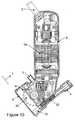
- the main case 5 acts as the handle and encloses the electric motor 19 (as in figure 10 .)
- the main case consists of two plastic injection moulded sides, which are fastened using screws 7. Vents 6, are provided for motor cooling.
- the power cable enters through strain relief 2.
- the waste from cutting is expelled through nozzle 3 (as in figures 1 , 2 and 10 .)
- the guard 10 moves with respect to the main case 5 in a direction shown by arrow 1, and in response to operator pressure. It is biased by spring 22, (as in figure 10 ) and is furthermore in a position which fully encloses blade 20.
- the guard 10 moves on four sliders shown in figure 8 (where 16 is a front view, 17 is a side view and 18 is a plan view.)
- the sliders are fixed in slots 14 (as in figures 6 and 7 ) in the guard 10. They are shown in position in figure 9 .
- the sliders move in grooves 9 (as in figures 1 to 4 .)
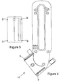
- Figures 3 and 4 show the main case mouldings and reveal the grooves 9 in full.
- Figure 5 is a view of the main case base, indicated by arrow 13, which shows an underneath view of the grooves 9.
- the depth adjuster 4 acts on base plate 8 to restrict the travel of guard 10, which consequently limits the exposure of blade 20 (as in figure 10 .)
- a scale 21, is provided to enable the depth to be set to a known value.
- Indication marks 12, (as in figures 1 and 2 ) show the chord length of the exposed blade. The line of cut is indicated, both behind and in front of the cut, by pointers 15 (as in figures 6 and 7 .)
- An advantage of the tool is that the contact between the bearings and the sliding members is not limited to a specific perpendicular height from the plane of the base plate. Such limited contact would increase the chances of jamming. Instead the contact is maintained over a range of heights, perpendicular to the base plate. In the prior art, the fit between the bearings and the grooves has to be more accurate due to the shorter the length of contact in order to prevent jamming and maintain the handle angle precision during operation.
- base plate location is improved in comparison to the abovementioned prior art as the base plate is easily held in place without the risk of sticking or wobbling, achieving increased safety for the user.
- a further advantage of the tool is that two existing ridged members of the power tool can be used as the housing grooves, therefore construction is cheaper and easier.
- a tool according to the claimed invention is shown having preferred, improved indication marks 23 marked with the same numbers as the depth scale 21.
- the point at which the cutting blade 24, enters and leaves the work piece, whilst cutting, will be shown by the number on scale 23, front and rear, which is the same number that is indicated on depth scale 21, by depth adjuster knob 4.
- the example in figure 12 shows the depth adjuster knob 4, set to give a cutting depth of 8mm, which is indicated on depth scale 21.
- the guard 10 has been depressed to the limit set by the depth adjuster exposing cutting blade 24.
- the indication marks 23 show that the cutting blade enters and leaves the base plate 8, and thus the work piece at the number 8, both front and rear.
- the advantage of the improved marking is that the point where the cutting blade will enter and leave the work piece can be seen before the cutting blade has been plunged into the work piece, as well as when the tool is depressed. Thus the tool can be positioned accurately for making cut outs.
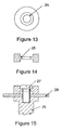
- Figure 13 shows a plan view of one version of a safety blade retaining washer and figure 14 shows a sectional side view.
- the inner section 25 is thinner than the outer rim.
- Figure 15 shows an assembly in which the blade retaining screw 27 clamps the cutting blade 28, to the driving shaft 26, using the safety blade retaining washer.
- the blade retaining washer is made from a brittle material, such as die cast zinc, to ensure a clean break.
- the thinned section 25, of the safety blade retaining washer is thinned on both sides symmetrically so that it may be fitted either way round.
- the advantages of using a safety blade retaining washer is improved safety and tool reliability.
- the release of the cutting blade from the driving shaft reduces wear and tear on the gearbox.
- the use of the retaining washer is not limited to the type of tool specifically illustrated in the described embodiments.
- the washer may be applicable to any tool with a rotary cutting blade, such as a saw, a planer and a lawnmower if desired.
Landscapes
- Engineering & Computer Science (AREA)
- Mechanical Engineering (AREA)
- Life Sciences & Earth Sciences (AREA)
- Wood Science & Technology (AREA)
- Forests & Forestry (AREA)
- Sawing (AREA)
Description
- The present invention relates to the field of hand-held power tools as per the preamble of
claim 1. Dependent claims 2-16 set out preferred embodiments. Hand operated power tools, of the type shown in European Patent No0993919 ,EP Application No 95934753.5 3239986 all have certain similarities. They each have a base plate which presses flat onto the work surface prior to and during the cutting operation. The cutting element is eased into the work piece by pressing the handle in a direction perpendicular to and towards the work surface, whilst the handle remains at a constant angle. The result is that the base plate and/or guard slides with respect to the handle. -
EP 0993919 (the closest prior art to the present invention) andEP 95934753.5 - With this form of indication the chord length of exposed cutting blade, for any given depth, cannot be seen until the guard has been retracted as far as the depth adjuster will allow. That is, it is only possible to determine the foremost and/or rearmost portions of the cutting blade when the blade is fully extended. Therefore, in the prior art, it is difficult for an operator to use the indication for positioning the tool, prior to cutting. This is a problem when cutting out because the tool should only be fed in a forwards direction, whilst cutting, and requires positioning exactly at the start of the cut.
- It would be desirable to have a means for indicating the position at which the blade will begin cutting before the tool is depressed and the blade is exposed.
- Accordingly, the present invention provides a hand operated power tool comprising the features of
claim 1. - In order to provide a better understanding of the present invention, examples will now be described by way of example only with reference to the accompanying Figures in which:
-
Figure 1 shows a right hand view of a complete tool, the tool falling outwith the scope of the present invention; -
Figure 2 shows a left hand view of the complete tool ofFigure 1 ; -
Figure 3 shows a left hand view of the main case moulding of the tool ofFigure 1 ; -
Figure 4 shows a right hand view of the main case moulding of the tool ofFigure 1 ; -
Figure 5 shows a base view of the assembled main case of the tool ofFigure 1 ; -
Figure 6 shows a sectional side view of the guard/base plate of the tool ofFigure 1 ; -
Figure 7 shows a plan view of the guard/base plate ofFigure 6 without the sliders fitted; -
Figure 8 shows a slider from three different views; -
Figure 9 shows a plan view of the guard/base plate of the tool ofFigure 1 with the sliders fitted; -
Figure 10 shows an inside view of the tool ofFigure 1 ; -
Figure 11 shows a right hand view of a hand operated power tool according to the invention with improved blade width indication; -
Figure 12 shows a right hand view of the tool with improved blade width indication ofFigure 11 , with the guard depressed; -
Figure 13 shows a plan view of a safety blade retaining washer; -
Figure 14 shows a sectional side view of a safety blade retaining washer; and -
Figure 15 shows a sectional side view of a safety blade retaining washer assembled with a blade retaining screw and a sectional side view of the cutting blade and driving shaft. - When the terms left or right are used throughout this description, it is assumed that the tool is being viewed from behind, looking along the direction of cut. Some features and hidden detail have been omitted for the sake of clarity.
- A hand operated power tool is shown in
figures 1 to 10 . The tool shown infigures 1 and2 falls outwith the scope of the invention claimed herein, but illustrates certain features in common with a tool falling within the scope of the claimed invention, which will be described below. - The
arrow 1 infigures 1 ,2 and7 points vertically to show the orientation of the tool when in use. - In
figures 1 and2 , themain case 5 acts as the handle and encloses the electric motor 19 (as infigure 10 .) The main case consists of two plastic injection moulded sides, which are fastened usingscrews 7.Vents 6, are provided for motor cooling. The power cable enters throughstrain relief 2. The waste from cutting is expelled through nozzle 3 (as infigures 1 ,2 and10 .) - The
guard 10, moves with respect to themain case 5 in a direction shown byarrow 1, and in response to operator pressure. It is biased byspring 22, (as infigure 10 ) and is furthermore in a position which fully enclosesblade 20. Theguard 10 moves on four sliders shown infigure 8 (where 16 is a front view, 17 is a side view and 18 is a plan view.) The sliders are fixed in slots 14 (as infigures 6 and 7 ) in theguard 10. They are shown in position infigure 9 . The sliders move in grooves 9 (as infigures 1 to 4 .)Figures 3 and4 show the main case mouldings and reveal thegrooves 9 in full.Figure 5 is a view of the main case base, indicated byarrow 13, which shows an underneath view of thegrooves 9. - The depth adjuster 4, (as in
figures 1 and2 ) acts onbase plate 8 to restrict the travel ofguard 10, which consequently limits the exposure of blade 20 (as infigure 10 .) Ascale 21, is provided to enable the depth to be set to a known value. Indication marks 12, (as infigures 1 and2 ) show the chord length of the exposed blade. The line of cut is indicated, both behind and in front of the cut, by pointers 15 (as infigures 6 and 7 .) An advantage of the tool is that the contact between the bearings and the sliding members is not limited to a specific perpendicular height from the plane of the base plate. Such limited contact would increase the chances of jamming. Instead the contact is maintained over a range of heights, perpendicular to the base plate. In the prior art, the fit between the bearings and the grooves has to be more accurate due to the shorter the length of contact in order to prevent jamming and maintain the handle angle precision during operation. - Thus, base plate location is improved in comparison to the abovementioned prior art as the base plate is easily held in place without the risk of sticking or wobbling, achieving increased safety for the user.
- A further advantage of the tool is that two existing ridged members of the power tool can be used as the housing grooves, therefore construction is cheaper and easier.
- With reference to
figures 11 and12 , a tool according to the claimed invention is shown having preferred, improvedindication marks 23 marked with the same numbers as thedepth scale 21. The point at which thecutting blade 24, enters and leaves the work piece, whilst cutting, will be shown by the number onscale 23, front and rear, which is the same number that is indicated ondepth scale 21, bydepth adjuster knob 4. The example infigure 12 shows thedepth adjuster knob 4, set to give a cutting depth of 8mm, which is indicated ondepth scale 21. Theguard 10, has been depressed to the limit set by the depth adjuster exposingcutting blade 24. The indication marks 23 show that the cutting blade enters and leaves thebase plate 8, and thus the work piece at thenumber 8, both front and rear. - The advantage of the improved marking is that the point where the cutting blade will enter and leave the work piece can be seen before the cutting blade has been plunged into the work piece, as well as when the tool is depressed. Thus the tool can be positioned accurately for making cut outs.
-
Figure 13 shows a plan view of one version of a safety blade retaining washer andfigure 14 shows a sectional side view. Theinner section 25 is thinner than the outer rim.Figure 15 shows an assembly in which theblade retaining screw 27 clamps thecutting blade 28, to the drivingshaft 26, using the safety blade retaining washer. - If the blade stops whilst the driving
shaft 26 is still turning theblade retaining screw 27 will tighten in the drivingshaft 26. This results in breaking of the thinnedinner section 25 of the blade retaining washer, thus releasing the blade from the driving shaft. - The blade retaining washer is made from a brittle material, such as die cast zinc, to ensure a clean break. The
main case 5, which surrounds the upper part of thecutting blade 24, and theguard 10, prevents the cutting blade from exposure to the operator when the safety blade retaining washer has broken. - The thinned
section 25, of the safety blade retaining washer is thinned on both sides symmetrically so that it may be fitted either way round. - The advantages of using a safety blade retaining washer is improved safety and tool reliability. In particular, the release of the cutting blade from the driving shaft reduces wear and tear on the gearbox.
- It will be evident that the use of the retaining washer is not limited to the type of tool specifically illustrated in the described embodiments. The washer may be applicable to any tool with a rotary cutting blade, such as a saw, a planer and a lawnmower if desired.
- In the preferred embodiment of the invention the safety features described above are combined on a single tool in order to improve the reliability and safety of the tool further.
- Further modifications and improvements may be added without departing from the scope of the invention herein intended as defined by the claims.
Claims (16)
- A hand operated power tool comprising:an operating head;a cutting blade (24);a depth adjuster (4) having an indicator scale (21) marked with numbers; anda guard (10) dimensioned to fit over and around the operating head and being a sliding fit thereon, said guard being movable relative to the operating head between a first position in which the cutting blade is covered, and a second position in which the cutting blade is exposed, the guard comprising: a base plate (8) adapted to abut a surface of a workpiece in which a cutout is to be formed, the cutting blade protruding through the base plate when the guard is in the second position; and a plurality of sides which extend from the base plate and, in use, away from the workpiece surface in which a cutout is to be formed and around the operating head of the tool;wherein the depth adjuster is for controlling the maximum extension of the cutting blade from the guard base plate;
and wherein a side of the guard is provided with indication marks (23);
characterised in that the indication marks on the guard are marked with numbers, and in that the indication marks on the guard correspond directly to marks of the depth adjustor indicator scale bearing the same numbers for indicating to a user the foremost and rearmost points at which the cutting blade protrudes from the guard, such that the points at which the cutting blade will enter and leave the workpiece can be seen when the guard is in the first position and thus before the cutting blade has been plunged into the workpiece, as well as when the guard is in the second position and thus when the tool has been depressed, to facilitate accurate positioning of the tool for making a cutout in the workpiece surface. - A hand operated power tool as claimed in claim 1, wherein slider bearings (18) are mounted between the guard and the operating head, so as to maintain alignment between the guard and the head over an operating range of movement of the guard.
- A hand operated power tool as claimed in claim 2, wherein four such slider bearings are provided spaced around the periphery of the guard.
- A hand operated power tool as claimed in claim 2 or claim 3, wherein the slider bearings comprise cooperating tongue and groove formations (18,9) on the guard and operating head or vice versa.
- A hand operated power tool as claimed in any of claims 2 to 4, wherein the slider bearings are coated with a material with a relatively low co-efficient of friction.
- A hand operated power tool as claimed in any of claims 2 to 4, wherein the slider bearings are made of a material with a relatively low co-efficient of friction.
- A hand operated power tool as claimed in claim 5 or claim 6, wherein the material with a relatively low co-efficient of friction is one of PTFE, polyacetal or polyamide.
- A hand operated power tool as claimed in any preceding claim, wherein the guard is resiliently biased towards the first position in which the cutting blade is covered.
- A hand operated power tool as claimed in any preceding claim, comprising pointers (15) for indicating the line of cut both behind and in front of the cut.
- A hand operated power tool as claimed in any preceding claim, wherein the cutting blade is a rotary cutting blade (24), and wherein the power tool comprises a driving shaft(26) and a retaining washer (25), said rotary cutting blade being held urged towards the driving shaft by said retaining washer so that the blade and shaft rotate together, and further wherein the retaining washer is frangible and substantial restriction of the rotation of the cutting blade causes the retaining washer to break, thereby releasing the blade from being urged towards the driving shaft.
- A hand operated power tool as claimed in claim 10, wherein the retaining washer is attached to the driving shaft by a screw (27) extending through a hole in the retaining washer and the cutting blade.
- A hand operated power tool as claimed in claim 11, wherein a substantial restriction of the rotation of the cutting blade causes a tightening of the screw in the driving shaft, said tightening causing the retaining washer to break.
- A hand operated power tool as claimed in any of claims 10 to 12, wherein the retaining washer comprises an outer region of a first thickness, and an inner region (25) of a second thickness, the second thickness being less than the first thickness.
- A hand operated power tool as claimed in claim 13, when dependent upon claim 11, wherein the fixing screw abuts the inner region, and the outer region abuts the cutting blade.
- A hand operated power tool as claimed in any of claims 10 to 14, wherein the retaining washer is made from a brittle material.
- A hand operated power tool as claimed in claim 15, wherein the brittle material is die cast zinc.
Applications Claiming Priority (3)
| Application Number | Priority Date | Filing Date | Title |
|---|---|---|---|
| GB0011437 | 2000-05-12 | ||
| GBGB0011437.1A GB0011437D0 (en) | 2000-05-12 | 2000-05-12 | Power tool guard |
| US10/051,225 US6757982B2 (en) | 2000-05-12 | 2002-01-18 | Safety improvements for power tool |
Publications (3)
| Publication Number | Publication Date |
|---|---|
| EP1177868A2 EP1177868A2 (en) | 2002-02-06 |
| EP1177868A3 EP1177868A3 (en) | 2005-12-07 |
| EP1177868B1 true EP1177868B1 (en) | 2008-08-20 |
Family
ID=29217360
Family Applications (1)
| Application Number | Title | Priority Date | Filing Date |
|---|---|---|---|
| EP01304286A Expired - Lifetime EP1177868B1 (en) | 2000-05-12 | 2001-05-14 | Safety improvements for power tool |
Country Status (4)
| Country | Link |
|---|---|
| US (1) | US6757982B2 (en) |
| EP (1) | EP1177868B1 (en) |
| DE (2) | DE20122513U1 (en) |
| GB (1) | GB0011437D0 (en) |
Cited By (4)
| Publication number | Priority date | Publication date | Assignee | Title |
|---|---|---|---|---|
| WO2011035718A1 (en) | 2009-09-24 | 2011-03-31 | 苏州宝时得电动工具有限公司 | Portable cutting machine |
| USD693664S1 (en) | 2011-11-15 | 2013-11-19 | Actervis Gmbh | Saw |
| CN102275183B (en) * | 2009-01-22 | 2015-02-04 | 苏州宝时得电动工具有限公司 | Portable circular saw |
| CN105345143A (en) * | 2010-09-21 | 2016-02-24 | 苏州宝时得电动工具有限公司 | Portable cutting machine |
Families Citing this family (22)
| Publication number | Priority date | Publication date | Assignee | Title |
|---|---|---|---|---|
| GB0011437D0 (en) * | 2000-05-12 | 2000-06-28 | Exact Precision Tools Limited | Power tool guard |
| WO2005118195A2 (en) * | 2004-05-28 | 2005-12-15 | Scientific Molding Corporation Ltd. | Hand-held circular saw, in particular plunge-cut saw |
| US7310879B1 (en) | 2006-07-27 | 2007-12-25 | Robert Bosch Gmbh | Cutting attachment having an adjustable foot for rotary hand tools |
| US7596872B2 (en) * | 2006-07-27 | 2009-10-06 | Robert Bosch Gmbh | Cutting attachment with a removable cover for rotary hand tools |
| USD564850S1 (en) | 2006-09-26 | 2008-03-25 | Jinding Group Co., Ltd. | Portion of a tool housing |
| GB0710034D0 (en) * | 2007-05-25 | 2007-07-04 | Gmca Pty Ltd | Improved planer |
| DE102008046705A1 (en) * | 2008-09-11 | 2010-03-18 | Mafell Ag | Handkreissäge |
| CN101863047B (en) * | 2009-04-20 | 2012-07-04 | 苏州宝时得电动工具有限公司 | Portable cutting machine |
| CN201493556U (en) * | 2009-09-07 | 2010-06-02 | 宁波捷美进出口有限公司 | Hand-held circular saw guard shield safe locking mechanism |
| CN201493906U (en) * | 2009-09-07 | 2010-06-02 | 宁波捷美进出口有限公司 | Hand-held circular saw cutting depth adjustment locking mechanism |
| CN102029430B (en) * | 2009-09-24 | 2013-06-05 | 苏州宝时得电动工具有限公司 | Portable cutting machine |
| CN102407381B (en) * | 2010-09-21 | 2014-06-04 | 苏州宝时得电动工具有限公司 | Portable cutting machine |
| CN102407387A (en) * | 2010-09-21 | 2012-04-11 | 苏州宝时得电动工具有限公司 | Portable cutting machine |
| CN102407385B (en) * | 2010-09-21 | 2014-07-02 | 苏州宝时得电动工具有限公司 | Portable cutting machine |
| CN103203776B (en) * | 2012-01-12 | 2016-04-06 | 苏州宝时得电动工具有限公司 | Portable circular saw and cutting-in control method thereof |
| US9044869B2 (en) * | 2012-02-06 | 2015-06-02 | Chervon (Hk) Limited | Electric circular saw |
| DE102012105520A1 (en) * | 2012-06-25 | 2014-04-24 | C. & E. Fein Gmbh | Depth stop for oscillating tool |
| EP3173188A1 (en) * | 2015-11-25 | 2017-05-31 | HILTI Aktiengesellschaft | Portable, hand held cutting-off machine |
| EP3537998B1 (en) * | 2016-11-11 | 2020-05-20 | Koninklijke Philips N.V. | Apparatus for callus removal |
| CN112171802B (en) * | 2020-09-11 | 2021-11-23 | 周懋强 | Mark opening equipment for washboard |
| CN114246633B (en) * | 2021-11-08 | 2024-03-01 | 莆田学院 | Circular depth-limiting electric bone saw for acetabulum |
| CN114888854A (en) * | 2022-04-25 | 2022-08-12 | 中国一冶集团有限公司 | Composite rotary wheel type electric hand tool |
Citations (2)
| Publication number | Priority date | Publication date | Assignee | Title |
|---|---|---|---|---|
| DE824256C (en) * | 1949-08-10 | 1951-12-10 | Hans Peter Schmanns | Portable universal machine, especially for woodworking and metalworking |
| US4942912A (en) * | 1989-06-06 | 1990-07-24 | Vermont American Corporation | Router attachment |
Family Cites Families (11)
| Publication number | Priority date | Publication date | Assignee | Title |
|---|---|---|---|---|
| US2627657A (en) * | 1951-08-27 | 1953-02-10 | L A Young Spring & Wire Corp | Fabric cutter guard |
| CH497251A (en) * | 1968-09-12 | 1970-10-15 | Steiner Hermann | Mobile device for making grooves |
| JPS532786A (en) * | 1976-06-29 | 1978-01-11 | Central Glass Co Ltd | Grinding material |
| DE3239986A1 (en) * | 1982-10-28 | 1984-05-03 | Robert Bosch Gmbh, 7000 Stuttgart | HAND MACHINE TOOL WITH A DISC-SHAPED TOOL |
| US5491963A (en) * | 1994-08-11 | 1996-02-20 | Jerez; Orlando | Garden cleaning implement for cutting/macerating weeds above and below ground |
| US5477845A (en) * | 1994-08-12 | 1995-12-26 | Zuzelo; Edward A. | Saw blade and mounting means for the same |
| AU3706095A (en) * | 1994-10-28 | 1996-05-23 | Neil Refson | A hand-operated power tool |
| US5881784A (en) * | 1996-07-19 | 1999-03-16 | Ryobi North America, Inc. | Biscuit cutter |
| DE19751620A1 (en) * | 1997-11-21 | 1999-05-27 | Harry Pietsch | Miller for cutting circular section slots for edge joints in wood |
| EP0993919A3 (en) * | 1998-10-07 | 2005-10-26 | Precision Tools Limited Exakt | Hand operated multi purpose power tool |
| GB0011437D0 (en) * | 2000-05-12 | 2000-06-28 | Exact Precision Tools Limited | Power tool guard |
-
2000
- 2000-05-12 GB GBGB0011437.1A patent/GB0011437D0/en not_active Ceased
-
2001
- 2001-05-14 DE DE20122513U patent/DE20122513U1/en not_active Expired - Lifetime
- 2001-05-14 DE DE01304286T patent/DE01304286T1/en active Pending
- 2001-05-14 EP EP01304286A patent/EP1177868B1/en not_active Expired - Lifetime
-
2002
- 2002-01-18 US US10/051,225 patent/US6757982B2/en not_active Expired - Fee Related
Patent Citations (2)
| Publication number | Priority date | Publication date | Assignee | Title |
|---|---|---|---|---|
| DE824256C (en) * | 1949-08-10 | 1951-12-10 | Hans Peter Schmanns | Portable universal machine, especially for woodworking and metalworking |
| US4942912A (en) * | 1989-06-06 | 1990-07-24 | Vermont American Corporation | Router attachment |
Cited By (4)
| Publication number | Priority date | Publication date | Assignee | Title |
|---|---|---|---|---|
| CN102275183B (en) * | 2009-01-22 | 2015-02-04 | 苏州宝时得电动工具有限公司 | Portable circular saw |
| WO2011035718A1 (en) | 2009-09-24 | 2011-03-31 | 苏州宝时得电动工具有限公司 | Portable cutting machine |
| CN105345143A (en) * | 2010-09-21 | 2016-02-24 | 苏州宝时得电动工具有限公司 | Portable cutting machine |
| USD693664S1 (en) | 2011-11-15 | 2013-11-19 | Actervis Gmbh | Saw |
Also Published As
| Publication number | Publication date |
|---|---|
| GB0011437D0 (en) | 2000-06-28 |
| DE20122513U1 (en) | 2005-12-15 |
| US6757982B2 (en) | 2004-07-06 |
| DE01304286T1 (en) | 2006-03-09 |
| US20030136011A1 (en) | 2003-07-24 |
| EP1177868A2 (en) | 2002-02-06 |
| EP1177868A3 (en) | 2005-12-07 |
Similar Documents
| Publication | Publication Date | Title |
|---|---|---|
| EP1177868B1 (en) | Safety improvements for power tool | |
| EP1644166B1 (en) | Circular saw having bevel and depth of cut detent system | |
| US8640346B2 (en) | Power tool | |
| EP2673123B1 (en) | Powered circular saw and method of use thereof | |
| US4335512A (en) | Attachment for a power hand saw | |
| CA1170149A (en) | Setting mechanisms especially for tools for carrying out routing and like operations | |
| US20080235961A1 (en) | Adjustable shoe assembly for a reciprocating saw | |
| US4971122A (en) | Fence and fence position adjusting mechanism in joint machine | |
| US7963043B2 (en) | Support shoe for a reciprocating saw | |
| US5815931A (en) | Cutting guide for controlling the direction and cut of a hand held power cutting tool | |
| WO2018050800A1 (en) | Concrete cutter with depth setting and retention system | |
| EP0788421B1 (en) | A hand-operated power tool | |
| US5678314A (en) | Hand power tool | |
| EP1837142A1 (en) | Miter Saw | |
| GB1565687A (en) | Cutting machine | |
| US6000449A (en) | Cutting head with exchangeable hard-metal cutting blades for wood working | |
| EP0042445B1 (en) | Depth of cut adjustment mechanism | |
| EP0884146A3 (en) | Plate joiner fence height adjustment system | |
| EP0884147A3 (en) | Plate joiner cutter travel adjustment system | |
| EP1514655B1 (en) | A shoe assembly for a reciprocating tool | |
| EP4292787A1 (en) | Hand-held planing tool | |
| EP0875345A1 (en) | Portable wood planing machine with switched reluctance motor | |
| JPH07304001A (en) | Portable circular saw base |
Legal Events
| Date | Code | Title | Description |
|---|---|---|---|
| PUAI | Public reference made under article 153(3) epc to a published international application that has entered the european phase |
Free format text: ORIGINAL CODE: 0009012 |
|
| AK | Designated contracting states |
Kind code of ref document: A2 Designated state(s): AT BE CH CY DE DK ES FI FR GB GR IE IT LI LU MC NL PT SE TR |
|
| AX | Request for extension of the european patent |
Free format text: AL;LT;LV;MK;RO;SI |
|
| RIN1 | Information on inventor provided before grant (corrected) |
Inventor name: REFSON, NEIL |
|
| 17P | Request for examination filed |
Effective date: 20050803 |
|
| PUAL | Search report despatched |
Free format text: ORIGINAL CODE: 0009013 |
|
| AK | Designated contracting states |
Kind code of ref document: A3 Designated state(s): AT BE CH CY DE DK ES FI FR GB GR IE IT LI LU MC NL PT SE TR |
|
| AX | Request for extension of the european patent |
Extension state: AL LT LV MK RO SI |
|
| DET | De: translation of patent claims | ||
| AKX | Designation fees paid |
Designated state(s): AT BE CH CY DE DK ES FI FR GB GR IE IT LI LU MC NL PT SE TR |
|
| 17Q | First examination report despatched |
Effective date: 20060202 |
|
| GRAP | Despatch of communication of intention to grant a patent |
Free format text: ORIGINAL CODE: EPIDOSNIGR1 |
|
| RAP1 | Party data changed (applicant data changed or rights of an application transferred) |
Owner name: EXAKT PRECISION TOOLS LIMITED |
|
| GRAS | Grant fee paid |
Free format text: ORIGINAL CODE: EPIDOSNIGR3 |
|
| GRAA | (expected) grant |
Free format text: ORIGINAL CODE: 0009210 |
|
| AK | Designated contracting states |
Kind code of ref document: B1 Designated state(s): AT BE CH CY DE DK ES FI FR GB GR IE IT LI LU MC NL PT SE TR |
|
| REG | Reference to a national code |
Ref country code: GB Ref legal event code: FG4D |
|
| REG | Reference to a national code |
Ref country code: CH Ref legal event code: EP |
|
| REG | Reference to a national code |
Ref country code: IE Ref legal event code: FG4D |
|
| REF | Corresponds to: |
Ref document number: 60135418 Country of ref document: DE Date of ref document: 20081002 Kind code of ref document: P |
|
| PG25 | Lapsed in a contracting state [announced via postgrant information from national office to epo] |
Ref country code: ES Free format text: LAPSE BECAUSE OF FAILURE TO SUBMIT A TRANSLATION OF THE DESCRIPTION OR TO PAY THE FEE WITHIN THE PRESCRIBED TIME-LIMIT Effective date: 20081201 Ref country code: NL Free format text: LAPSE BECAUSE OF FAILURE TO SUBMIT A TRANSLATION OF THE DESCRIPTION OR TO PAY THE FEE WITHIN THE PRESCRIBED TIME-LIMIT Effective date: 20080820 |
|
| PG25 | Lapsed in a contracting state [announced via postgrant information from national office to epo] |
Ref country code: AT Free format text: LAPSE BECAUSE OF FAILURE TO SUBMIT A TRANSLATION OF THE DESCRIPTION OR TO PAY THE FEE WITHIN THE PRESCRIBED TIME-LIMIT Effective date: 20080820 Ref country code: FI Free format text: LAPSE BECAUSE OF FAILURE TO SUBMIT A TRANSLATION OF THE DESCRIPTION OR TO PAY THE FEE WITHIN THE PRESCRIBED TIME-LIMIT Effective date: 20080820 |
|
| PG25 | Lapsed in a contracting state [announced via postgrant information from national office to epo] |
Ref country code: BE Free format text: LAPSE BECAUSE OF FAILURE TO SUBMIT A TRANSLATION OF THE DESCRIPTION OR TO PAY THE FEE WITHIN THE PRESCRIBED TIME-LIMIT Effective date: 20080820 |
|
| PG25 | Lapsed in a contracting state [announced via postgrant information from national office to epo] |
Ref country code: DK Free format text: LAPSE BECAUSE OF FAILURE TO SUBMIT A TRANSLATION OF THE DESCRIPTION OR TO PAY THE FEE WITHIN THE PRESCRIBED TIME-LIMIT Effective date: 20080820 |
|
| PG25 | Lapsed in a contracting state [announced via postgrant information from national office to epo] |
Ref country code: PT Free format text: LAPSE BECAUSE OF FAILURE TO SUBMIT A TRANSLATION OF THE DESCRIPTION OR TO PAY THE FEE WITHIN THE PRESCRIBED TIME-LIMIT Effective date: 20090120 |
|
| PLBE | No opposition filed within time limit |
Free format text: ORIGINAL CODE: 0009261 |
|
| STAA | Information on the status of an ep patent application or granted ep patent |
Free format text: STATUS: NO OPPOSITION FILED WITHIN TIME LIMIT |
|
| 26N | No opposition filed |
Effective date: 20090525 |
|
| PG25 | Lapsed in a contracting state [announced via postgrant information from national office to epo] |
Ref country code: IT Free format text: LAPSE BECAUSE OF FAILURE TO SUBMIT A TRANSLATION OF THE DESCRIPTION OR TO PAY THE FEE WITHIN THE PRESCRIBED TIME-LIMIT Effective date: 20080820 |
|
| REG | Reference to a national code |
Ref country code: CH Ref legal event code: NV Representative=s name: MURGITROYD & COMPANY |
|
| PG25 | Lapsed in a contracting state [announced via postgrant information from national office to epo] |
Ref country code: MC Free format text: LAPSE BECAUSE OF NON-PAYMENT OF DUE FEES Effective date: 20090531 |
|
| PG25 | Lapsed in a contracting state [announced via postgrant information from national office to epo] |
Ref country code: SE Free format text: LAPSE BECAUSE OF FAILURE TO SUBMIT A TRANSLATION OF THE DESCRIPTION OR TO PAY THE FEE WITHIN THE PRESCRIBED TIME-LIMIT Effective date: 20081120 |
|
| PG25 | Lapsed in a contracting state [announced via postgrant information from national office to epo] |
Ref country code: GR Free format text: LAPSE BECAUSE OF FAILURE TO SUBMIT A TRANSLATION OF THE DESCRIPTION OR TO PAY THE FEE WITHIN THE PRESCRIBED TIME-LIMIT Effective date: 20081121 |
|
| PG25 | Lapsed in a contracting state [announced via postgrant information from national office to epo] |
Ref country code: LU Free format text: LAPSE BECAUSE OF NON-PAYMENT OF DUE FEES Effective date: 20090514 |
|
| PG25 | Lapsed in a contracting state [announced via postgrant information from national office to epo] |
Ref country code: TR Free format text: LAPSE BECAUSE OF FAILURE TO SUBMIT A TRANSLATION OF THE DESCRIPTION OR TO PAY THE FEE WITHIN THE PRESCRIBED TIME-LIMIT Effective date: 20080820 |
|
| PG25 | Lapsed in a contracting state [announced via postgrant information from national office to epo] |
Ref country code: CY Free format text: LAPSE BECAUSE OF FAILURE TO SUBMIT A TRANSLATION OF THE DESCRIPTION OR TO PAY THE FEE WITHIN THE PRESCRIBED TIME-LIMIT Effective date: 20080820 |
|
| PGFP | Annual fee paid to national office [announced via postgrant information from national office to epo] |
Ref country code: CH Payment date: 20120522 Year of fee payment: 12 Ref country code: IE Payment date: 20120528 Year of fee payment: 12 |
|
| REG | Reference to a national code |
Ref country code: CH Ref legal event code: PL |
|
| PG25 | Lapsed in a contracting state [announced via postgrant information from national office to epo] |
Ref country code: CH Free format text: LAPSE BECAUSE OF NON-PAYMENT OF DUE FEES Effective date: 20130531 Ref country code: LI Free format text: LAPSE BECAUSE OF NON-PAYMENT OF DUE FEES Effective date: 20130531 |
|
| REG | Reference to a national code |
Ref country code: IE Ref legal event code: MM4A |
|
| PG25 | Lapsed in a contracting state [announced via postgrant information from national office to epo] |
Ref country code: IE Free format text: LAPSE BECAUSE OF NON-PAYMENT OF DUE FEES Effective date: 20130514 |
|
| REG | Reference to a national code |
Ref country code: FR Ref legal event code: PLFP Year of fee payment: 15 |
|
| PGFP | Annual fee paid to national office [announced via postgrant information from national office to epo] |
Ref country code: FR Payment date: 20150422 Year of fee payment: 15 |
|
| PGFP | Annual fee paid to national office [announced via postgrant information from national office to epo] |
Ref country code: DE Payment date: 20151104 Year of fee payment: 15 |
|
| REG | Reference to a national code |
Ref country code: GB Ref legal event code: 732E Free format text: REGISTERED BETWEEN 20160512 AND 20160518 |
|
| REG | Reference to a national code |
Ref country code: DE Ref legal event code: R119 Ref document number: 60135418 Country of ref document: DE |
|
| REG | Reference to a national code |
Ref country code: FR Ref legal event code: ST Effective date: 20170131 |
|
| PG25 | Lapsed in a contracting state [announced via postgrant information from national office to epo] |
Ref country code: FR Free format text: LAPSE BECAUSE OF NON-PAYMENT OF DUE FEES Effective date: 20160531 Ref country code: DE Free format text: LAPSE BECAUSE OF NON-PAYMENT OF DUE FEES Effective date: 20161201 |
|
| PGFP | Annual fee paid to national office [announced via postgrant information from national office to epo] |
Ref country code: GB Payment date: 20190401 Year of fee payment: 19 |
|
| GBPC | Gb: european patent ceased through non-payment of renewal fee |
Effective date: 20200514 |
|
| PG25 | Lapsed in a contracting state [announced via postgrant information from national office to epo] |
Ref country code: GB Free format text: LAPSE BECAUSE OF NON-PAYMENT OF DUE FEES Effective date: 20200514 |