TECHNICAL FIELD
The present invention relates to an implantable
electrode lead used together with an implantable heart
pacemaker or implantable defibrillator, and an
implantable medical instrument using the implantable
electrode lead.
BACKGROUND ART
Many types of conventional electrode leads
implantable in living bodies (to be referred to as
implantable electrode leads hereinafter) which are used
together with implantable heart pacemakers or
implantable defibrillators, are known.
An implantable electrode lead is generally
comprised of an electrode for supplying an electrical
stimulation pulse to the heart or sensing an
electrically evoked response of the heart, an
electrical connector connected to a heart pacemaker (or
defibrillator), and a lead body made up of an
electrical conductor wire for connecting the electrode
and electrical connector to each other and transmitting
an electrical signal between the electrode and heart
pacemaker (or defibrillator) and an electrical
insulation covering the electrical conductor wire.
In the implantable electrode lead, the electrode
and part of the lead body are inserted in the heart and
vein, while the remaining lead body and the electrical
connector are placed outside the vein and connected to
the connection housing of the heart pacemaker or
implantable defibrillator.
As an example of a lead body for an implantable
electrode lead, a bipolar type lead body in which a
plurality of insulation-coated conductor are connected
parallel to each other is used, as shown in Japanese
Patent Laid-Open No. 11-333000. The conductor wires
are wound parallel to each other insulated from each
other so as to form a coil, and the conductor wires are
covered with a sheath, thus forming a lead body.
According to another general lead body, one with
a coaxial structure is available, which is comprised of
two types of conductor coils with different average
diameters, an insulating sheath located between the
conductor coils, and a sheath located at the outermost
surface of the lead body.
A bipolar type implantable electrode lead body
comprised of a plurality of conductor wires with
respect to one electrode is used because, even if one
of the conductor wires is disconnected, as long as the
remaining conductor wires are connected normally, an
electrical signal from the heart pacemaker can be
continuously transmitted to the living tissue.
As the implantable electrode lead, one with a
small energy loss in the conductor wires is sought.
For this reason, two conductor wires with the same low
resistance are used.
In a conventional implantable electrode lead
using two low-resistance conductor wires, even if one
conductor wire is disconnected, this produces a small
change in electrical resistance, as will be described
later. Therefore, it is rather difficult to externally
detect disconnection from a change in electrical
resistance after the implantable electrode lead is
implanted in the living body.
This will be described in detail with reference
to Figs. 14 and 15.
Fig. 14 shows a case in which a bipolar type
implantable electrode lead, comprised of two
low-resistance conductor wires connected parallel with
each other, is connected to a living tissue. The lead
body of an implantable electrode lead 60 is comprised
of two portions, i.e., a tip electrode-side lead
resistor 61 and ring electrode-side lead resistor 62.
The implantable electrode lead 60 and the living tissue
32 are connected to each other through a tip electrode
4 and ring electrode 3, and the living tissue 32 and
the implantable electrode lead 60 substantially
electrically form a series circuit as shown in Fig. 14.
The implantable electrode lead 60 is connected to an
implantable heart pacemaker through a connector pin 1
and connector ring 2.
Each of the tip electrode-side lead resistor 61
and ring electrode-side lead resistor 62 is comprised
of two conductor wires with the same resistance (R1).
To obtain the resistance R1 used for the implantable
heart pacemaker, for example, a low-resistance
conductor wire with approximately 16 Ω is used. A
bioelectrical resistance 32 (R4) of the living tissue
is approximately 1,000 Ω.
Figs. 15A and 15B show a case wherein changes in
resistance that occur when, of the four conductor wires,
one conductor wire of the tip electrode-side lead
resistor 61 is disconnected with the condition
described above are obtained. Fig. 15A shows changes
in electrical resistance upon disconnection. The
resistance of the tip electrode-side lead resistor 61
increases from 7.88 Ω to 15.76 Ω upon disconnection.
Fig. 15B shows a change in total electrical
resistance obtained on the basis of Fig. 15A. Although
the total electrical resistance after disconnection
(1,023.63 Ω) is slightly larger than that (1,015.76 Ω)
obtained before disconnection, the increase is small,
approximately 1% (the ratio of total electrical
resistance before disconnection to that after
disconnection: 1.008). Also, since the bioelectical
resistance sometimes fluctuates by approximately
several 10 Ω, it is difficult to determine
disconnection from the 1% increase in resistance.
As another lead body for the bipolar type
implantable electrode lead, one with a coaxial
structure is also available, which is comprised of two
types of conductor coils with different average
diameters, an insulating sheath located between the
conductor coils, and a sheath located at the outermost
surface of the lead body.
When the conductor wires of the same pole are not
insulated from each other, as in the conventional
coaxial structure, the adjacent conductor wires are
largely influenced by the contact resistance. As the
contact resistance varies depending on the movement or
deformation of the lead in the living body, it is
sometimes difficult to externally detect the contact
resistance from a change in resistance.
When, however, an implantable electrode lead used
in a heart pacemaker or implantable defibrillator is
completely disconnected, the treatment necessary for
the patient cannot be performed, sometimes leading to
the worst result such as death of the patient. For
this reason, it is desired that a symptom of
disconnection of the implantable electrode lead be
found at an early stage before complete disconnection.
DISCLOSURE OF INVENTION
The present invention has been made in view of
the above problems of the prior art, and has as its
object to provide an implantable electrode lead with a
bipolar type insulated parallel-wire coil structure, in
which electrical resistance can be kept low, and when
one of a plurality of conductor wires arranged for one
electrode is disconnected, a change in electrical
resistance generated by disconnection is detected
without being influenced by a contact resistance, so
that the symptom of disconnection of the implantable
electrode lead can be detected at an early stage before
complete disconnection.
It is another object of the present invention to
provide an implantable medical instrument that uses
this implantable electrode lead and can be used more
safely.
In order to achieve the above objects, the
implantable electrode lead according to the present
invention has the following structure.
More specifically, there is provided an
implantable electrode lead having a distal end provided
with at least one electrode to be implanted in a
predetermined portion of a living body in order to
perform at least one of transmission of an electrical
stimulation pulse to a living body and sensing of an
electrical signal from the living body, a proximal end
provided with connecting means to be connected to an
implantable medical instrument, and a lead body
provided between the distal end and the proximal end
and adapted to electrically connect the electrode and
the connecting means to each other, characterized in
that the lead body includes a plurality of wires with
different mechanical characteristics and insulated from
each other, the plurality of wires being electrically
connected to the at least one electrode to be parallel
to each other.
Preferably, the plurality of wires are wires with
different electrical resistances.
Preferably, each of the wires has a single layer
made of at least one metal material or alloy material,
or a composite wire with a plurality of different
single layers made of at least one metal material or
alloy material.
Preferably, the composite wire with the plurality
of different single layers has a cladding structure
obtained by stacking a plurality of types of single
layers made of different types of metal materials or
alloy materials, or by covering a first single layer
among the plurality of types of single layers with a
second single layer among the plurality of types of
single layers.
Preferably, the plurality of wires are structured
by using different materials.
Preferably, among the plurality of wires, a first
wire has an electrical resistivity of not more than
5 µΩ·cm and a second wire has an electrical resistivity
of not less than 5 µΩ·cm.
Preferably, the composite wire has a first single
layer made of a metal material or alloy material with
an electrical resistivity of not more than 5 µΩ·cm and
a second single layer made of a metal material or alloy
material with an electrical resistivity of not less
than 5 µΩ·cm.
Preferably, the first and second single layers of
the composite wire contain silver and a cobalt alloy,
respectively.
Preferably, the lead body comprises a helical
parallel coil of the plurality of wires insulated from
each other.
In order to achieve the above objects, an
implantable medical instrument according to the present
invention has the following arrangements.
More specifically, there is provided an
implantable medical instrument using an implantable
electrode lead having an electrode to be implanted in a
predetermined portion and a lead body electrically
connected to the electrode, wherein the lead body
includes a plurality of wires with different mechanical
characteristics and insulated from each other, the
plurality of wires being electrically connected to the
at least one electrode parallel to each other, and the
implantable medical instrument has informing means for
discriminating and informing that at least one of the
different wires is fractured.
Preferably, the implantable medical instrument
further has measuring means for measuring a motion
state or posture of the living body where the electrode
is implanted.
Preferably, the informing means measures a
parameter that changes on the basis of a change in
total electrical resistance of the plurality of wires,
compares the parameter with a preset reference
parameter, and informs that at least one of the
plurality of wires is fractured when the parameter that
changes is smaller than the reference parameter.
Preferably, the parameter includes either one of
current, frequency, and time.
Preferably, the measuring means further has
acceleration sensor means for measuring an acceleration,
and measures the motion state or posture of the living
body on the basis of a measurement result of the
acceleration sensor means.
Preferably, the implantable medical instrument
further has storage means, and when a measurement
result obtained by the measuring means satisfies a
predetermined condition, the measurement result is
recorded in the storage means.
Preferably, the lead body comprises a helical
parallel coil of the plurality of wires insulated from
each other.
BRIEF DESCRIPTION OF DRAWINGS
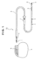
Fig. 1 is a view showing an example of an
implantable electrode lead and an implantable
instrument using the same;
Fig. 2A is a sectional view of a low-resistance
conductor wire;
Fig. 2B is a sectional view of a high-resistance
conductor wire;
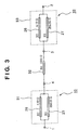
Fig. 3 is a circuit diagram obtained when an
implantable electrode lead is connected to the living
body;
Fig. 4A is a sectional view of an implantable
electrode lead;
Fig. 4B is a sectional view of an implantable
electrode lead with another arrangement;
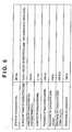
Fig. 5 is a table showing the sizes and
characteristics of conductor wires and a conductor
coil;
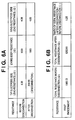
Fig. 6A is a table showing electrical resistances
before and after disconnection when the implantable
electrode lead is connected to the living body;
Fig. 6B is a table showing a change in total
electrical resistance upon disconnection when the
implantable electrode lead is connected to the living
body;
Fig. 7A is a sectional view of a low-resistance
conductor wire;
Fig. 7B is a sectional view of a high-resistance
conductor wire;
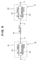
Fig. 8 is a circuit diagram obtained when an
implantable electrode lead is connected to the living
body;
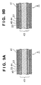
Fig. 9A is a sectional view of an implantable
electrode lead;
Fig. 9B is a sectional view of an implantable
electrode lead with another arrangement;
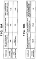
Fig. 10A is a table showing electrical
resistances before and after disconnection when the
implantable electrode lead is connected to the living
body;
Fig. 10B is a table showing a change between a
total electrical resistance before disconnection and
that after disconnection when an implantable electrode
lead is connected to the living body;
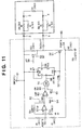
Fig. 11 shows an electrical resistance
measurement unit;
Fig. 12 is a timing chart of the respective
signals;
Fig. 13 shows a disconnection early detection
system;
Fig. 14 is a circuit diagram obtained when a
conventional implantable electrode lead is connected to
the living body;
Fig. 15A is prior art data showing electrical
resistances before and after disconnection when the
conventional implantable electrode lead is connected to
the living body; and
Fig. 15B is prior art data showing a change in
total electrical resistance upon disconnection when the
conventional implantable electrode lead is connected to
the living body.
BEST MODE FOR CARRYING OUT THE INVENTION
The preferred embodiments of the present
invention will be exemplified in detail with reference
to the accompanying drawings. Note that the scope of
the present invention is not limited to the relative
positions, numerical values, and the like of the
constituent elements described in the embodiments
unless otherwise specified.
[First Embodiment]
[Overall Arrangement of Heart Pacemaker and
Implantable Electrode Lead]
Fig. 1 is a view showing a bipolar type
implantable electrode lead 10 as an implantable
electrode lead according to the first embodiment of the
present invention, and a heart pacemaker 8 as an
example of an implantable instrument using it.
Referring to Fig. 1, the implantable electrode
lead 10 has a tip electrode 4 at its distal end
implanted in the heart and a ring electrode 3 on its
outer surface near the tip electrode 4, and a connector
pin 1 at its proximal end to be connected to the heart
pacemaker 8 and a connector ring 2 on its outer surface
near the connector pin 1, and is formed of a
predetermined-length flexible lead body 5 that
electrically connects these components to each other.
The tip electrode 4 is electrically connected to
the connector pin 1, and the ring electrode 3 is
electrically connected to the connector ring 2. The
connector pin 1 and connector ring 2 are mechanically
and electrically detachably connected to a connector
cavity 9 for the heart pacemaker 8 or an implantable
defibrillator (not shown).
An endocardium fixing portion 6, having such a
shape that it is caught by a trabeculae carneae or
chorda in the heart cavity so as to fix the implantable
electrode lead 10 to an endocardium, thereby setting
the implantable electrode lead 10 immobile, is provided
near the tip electrode 4.
A sleeve 7 serves to protect the lead body 5 when
the lead body 5 is fixed to the living tissue near a
vein inserting portion, and is mounted on the outer
surface of the lead body 5 so as to be movable in the
longitudinal direction of the lead body 5. The lead
body 5 is fixed as it is sutured together with the
outer surface of the sleeve 7 to the living tissue.
[Bipolar Type Implantable Electrode Lead]
A conductor coil and conductor wires that make up
the lead body 5 will be described with reference to
Figs. 2 to 4.
Figs. 4A and 4B are each a sectional view of a
portion indicated by arrows A - A of the lead body 5 in
Fig. 1, and show a case wherein two low- resistance
conductor wires 20 and 26 and two high- resistance
conductor wires 23 and 27 are arranged in different
manners.
The lead body 5 is made up of a conductor coil 42
with an insulated four-parallel-wire structure obtained
by helically winding the insulation-coated conductor
wires 20, 23, 26, and 27, and an insulating sheath 41
for insulating and covering the conductor coil 42. The
lead body 5 is narrow in order to reduce the
compression force repeatedly received between the
clavic and first rib.
The conductor coil 42 is formed of four conductor
wires, two of which are the low- resistance conductor
wires 20 and 26 with small electrical resistances shown
in Fig. 2A, and the remaining two of which are the
high- resistance conductor wires 23 and 27 with large
electrical resistances shown in Fig. 2B. These four
conductor wires make up the insulated
four-parallel-wire structure shown in Figs. 4A and 4B,
so the internal stress acting on the respective
conductor wires, when the lead body 5 deforms, is
reduced.
Of the four conductor wires, two (a low- and a
high-resistance conductor wires 20 and 23) are
connected parallel to each other between the connector
pin 1 and tip electrode 4, as shown in Fig. 3, to form
a tip electrode-side lead resistor 31, while the
remaining two (a low- and a high-resistance conductor
wires 26 and 27) are connected parallel to each other
between the connector ring 2 and ring electrode 3, to
form a ring electrode-side lead resistor 33.
The two low- resistance conductor wires 20 and 26
and the two high- resistance conductor wires 23 and 27
can have either one of the arrangements shown in
Figs. 4A and 4B.
The low- resistance conductor wires 20 and 26 and
the high- resistance conductor wires 23 and 27 will be
described with reference to Figs. 2A and 2B. The first
layer (cladding) of each of the low- resistance
conductor wires 20 and 26 is an insulation coat for
insulating the core from the outside, and is made of a
fluoroplastic material. The second layer (core) serves
to transmit an electrical signal, and is made of a
material with a low electrical resistivity (second
metal material 21), e.g., silver or copper. In this
embodiment, silver is used.
The first layer (cladding) of each of the
high- resistance conductor wires 23 and 27 is also
formed of an insulation coat made of a fluoroplastic
material in order to insulate the core from the outside.
The second layer (core) serves to transmit an
electrical signal and is made of a material with a
lower electrical resistivity (second metal material 24),
e.g., stainless steel or a cobalt-group alloy. In this
embodiment, MP35N as a cobalt-group alloy with
excellent corrosion resistance and mechanical
characteristics is used.
A case will be described in which the bipolar
type implantable electrode lead 10 formed by connecting
two low-resistance conductor wires parallel to each
other is connected to the living tissue and an
implantable heart pacemaker.
The lead body of the implantable electrode lead
10 is formed of two portions, i.e., the tip
electrode-side lead resistor 31 and ring electrode-side
lead resistor 33. The implantable electrode lead 10
and the living tissue are connected to each other
through the tip electrode 4 and ring electrode 3, and
the living tissue and the implantable electrode lead 10
substantially electrically form a series circuit as
shown in Fig. 3. The implantable electrode lead 10 is
connected to an implantable heart pacemaker through the
connector pin 1 and connector ring 2.
The tip electrode-side lead resistor 31 is
comprised of the low- and high- resistance conductor
wires 20 and 23, and the ring electrode-side lead
resistor 33 is comprised of the low- and
high- resistance conductor wires 26 and 27. In this
embodiment, as shown in Fig. 5, the coil using the
low- and high- resistance conductor wires 20 and 23 has
a length of 550 mm. The resistances are 4.06 Ω and
258.55 Ω respectively. The bioelectrical resistance 32
of the living tissue is approximately 1,000 Ω.
[Mechanical Strength of Implantable Electrode Lead]
Assume that, while the implantable electrode lead
10 is attached to the living tissue, a tensile stress
repeatedly acts on the implantable electrode lead 10,
so one of the four conductor wires making up the
implantable electrode lead 10 is disconnected. The
tensile strength of each of the low- resistance
conductor wires 20 and 26 is 290 MPa, and that of each
of the high- resistance conductor wires 23 and 27 is
520 MPa.
With these conditions, when a tensile stress
repeatedly acts on the implantable electrode lead 10,
either one of the two low- resistance conductor wires 20
and 26 is supposed to fracture first.
[Change in Total Electrical Resistance Upon Fracture
of Low-Resistance Conductor Wire]
A case will be described wherein a change in
electrical resistance that occurs when the
low-resistance conductor wire 20 fractures under the
conditions of Fig. 3 is obtained.
The total electrical resistance (Ω) formed of
the implantable electrode lead 10 and the living tissue
is given by the following equation (1):
Total Electrical Resistance
= Tip Electrode-Side Lead Resistance
+ Bioelectrical Resistance
+ Ring Electrode-Side Lead Resistance
Assume that the bioelectrical resistance is
1,000 Ω and that the tip electrode-side lead
resistance or electrode-side ring lead resistance is
only the resistance of a conductor coil formed of two
wires parallel to each other, as shown in Fig. 3. The
resistances in the electrode and connecting portions
are neglegible.
Fig. 6A and 6B show results of changes in
resistance which are obtained by using equation (1)
when the low-resistance conductor wire 20 of the tip
electrode-side lead resistor 31 is disconnected with
the conditions of Fig. 5.
Fig. 6A shows a change in resistance upon
disconnection of the respective portion. The
resistance of the tip electrode-side lead resistor 61
increases from 4.06 Ω to 258.55 Ω. As a result, as
shown in Fig. 6B, the total electrical resistance
increases from 1,008.13 Ω to 1,262.61 Ω. The
resistance increases by 25% due to disconnection (the
ratio of total electrical resistance before
disconnection to that after disconnection: 1.25).
This result is compared against the prior art
disconnect condition shown in Figs. 15A and 15B
described above. When two identical low-resistance
conductor wires are used (Figs. 15A and 15B), the
increase in resistance is 1%. When conductor wires
with different resistances are used, as in this
embodiment (Figs. 6A and 6B), the resistance after
disconnection can be larger than that before
disconnection by up to 25%. Therefore, even if the
bioelectrical resistance slightly changes,
disconnection of one low-resistance conductor wire can
be determined by measuring the resistances before and
after disconnection.
When the total electrical resistance
(1,008.13 Ω) before disconnection of this embodiment
is compared with the conventional total electrical
resistance (1,015.76 Ω) obtained with low-resistance
conductor wires, it decreases by only 1%. Thus, the
implantable electrode lead 10 according to this
embodiment can maintain a low resistance of almost the
conventional level.
When a fracture that greatly increases the
electrical resistance, although not leading to
disconnection, occurs in one of the plurality of
conductor wires of the conductor wires, the symptom of
disconnection of the implantable electrode lead can be
detected.
In the case described above, this embodiment is
applied to measurement of a resistance between the
connector pin 1 and connector ring 2, that is, in the
bipolar mode. It is readily understood that the same
effect can be obtained in measurement of a resistance
between the ring electrode 3 or tip electrode 4 and
another reference point, e.g., the main body case of
the heart pacemaker, i.e., in the unipolar mode.
[Second Embodiment]
An implantable electrode lead 11 according to the
second embodiment of the present invention will be
described with reference to Figs. 7 to 10.
The second embodiment is different from the
implantable electrode lead 10 of the first embodiment
in only low- resistant conductor wires 40 and 44 used in
a conductor coil 43 constituting the implantable
electrode lead 11 shown in Fig. 7A. The arrangement,
structure, operation, and the like of high- resistance
conductor wires 23 and 27 and the like shown in Fig. 7B
are entirely the same as those of the first embodiment.
The same arrangements as in the first embodiment are
denoted by the same reference numerals, and a
description thereof will be omitted.
Each of the low- resistant conductor wires 40 and
44 has a three-layered structure as shown in Fig. 7A.
The first layer (cladding) is an insulating film 22
fabricated from a fluoroplastic material. The second
layer (first core) is fabricated from a first metal
material 24 with a comparatively high electrical
resistivity, e.g., stainless steel or a cobalt-group
alloy, and has excellent corrosion resistance and
mechanical characteristics.
The third layer (second core) is fabricated from
a second metal material 21 with a low electrical
resistivity, e.g., silver or copper. The second and
third layers are brought into contact with each other,
so the electrical resistance of the entire conductor
wire is suppressed. In this embodiment, MP35N, which
is a cobalt-group alloy, is used as the first metal
material 24, and silver with a low electrical
resistivity is used as the second metal material 21.
In this embodiment, the low-resistant conductor
wire 40 with the three-layered structure shown in
Fig. 7A is used because, by covering a silver wire
having a low fracture strength with the cobalt-group
alloy (MP35N), the silver wire is protected and defects
formed in the silver surface during fabrication of the
silver layer are decreased. The low-resistant
conductor wire 40 has a slightly higher fracture
strength than that of the low-resistance conductor wire
20, although it is lower than that of the
high-resistance conductor wire 23.
As the arrangement of the conductor coil 43 using
the two low- resistant conductor wires 40 and 44 and two
high- resistance conductor wires 23 and 27, either one
of embodiments shown in Figs. 9A and 9B can be selected.
The arrangement formed by connecting the
implantable electrode lead 11 to the living tissue is
as shown in Figs. 9A and 9B. The resistances of the
low- resistant conductor wires 40 and 44 are 15 Ω in
the case of this embodiment wherein the conductor coil
has a length of 550 mm. Other resistances are equal to
those of the first embodiment shown in Fig. 5.
[Change in Total Electrical Resistance Upon Fracture
of Low-Resistance Conductor Wire]
Assume that, with the implantable electrode lead
11 being attached to the living tissue as shown in
Fig. 8, a tensile stress repeatedly acts on the
implantable electrode lead 11, as described above, so
one of the four conductor wires constituting the
implantable electrode lead 11 is accidentally fractured.
The tensile strengths of the low- resistant
conductor wires 40 and 44 are lower than those of the
high- resistance conductor wires 23 and 27. Hence, with
the above conditions, when a tensile stress repeatedly
acts on the implantable electrode lead 11, either one
of the two low- resistance conductor wires 40 and 44 is
supposed to fracture first.
A change in electrical resistance that occurs
when the low-resistance conductor wire 40 fractures
with the conditions of Fig. 8 is obtained. Figs. 10A
and 10B show the results.
Fig. 10A shows a change in resistance upon
disconnection. The resistance of the tip
electrode-side lead resistor 51 increases from 14.85 Ω
to 258.55 Ω upon disconnection. As shown in Fig. 10B,
the total electrical resistance after disconnection
obtained from equation (1) is higher than that obtained
before disconnection by 24%, as shown in Fig. 10B (the
ratio of total electrical resistance before
disconnection to that after disconnection: 1.24).
The rate of increase of the total electrical
resistance after disconnection is nearly the same as
the result obtained in the first embodiment (Figs. 6A
and 6B). Hence, it is apparent that in the second
embodiment as well, disconnection of the low- resistant
conductor wire 40 or 44 can be detected with the same
detection sensitivity as that of the first embodiment.
When the total electrical resistance
(1,029.70 Ω) before disconnection of this embodiment
is compared with the conventional total electrical
resistance (1,015.76 Ω) obtained with low-resistance
conductor wires, it increases by only 1%. Thus, the
implantable electrode lead 11 according to this
embodiment can maintain a low resistance of almost the
prior art level.
From the foregoing, with either the implantable
electrode lead 10 or 11, the total electrical
resistance can be suppressed low, and when one
conductor wire is accidentally fractured, it can be
detected with a high sensitivity.
When a fracture that greatly increases the
electrical resistance, although not leading to
disconnection, occurs in one of the plurality of
conductor wires, a symptom of disconnection of the
implantable electrode lead can be detected.
In the above embodiment, two wires connected
parallel to each other are implemented by using metal
materials with different electrical resistances and
mechanical characteristics. However, according to the
principle of the present invention, the metal materials
used to form the respective wires do not necessarily
have different characteristics.
Even if the two wires are made of one metal
material, they can have different electrical
resistances and mechanical characteristics by only
changing the shapes of the wires, e.g., making one wire
thinner than the other or by forming a groove in the
outer surface of one wire. As a result, degradation in
lead can be detected at an early stage.
[Measurement of Total Electrical Resistance]
A method of measuring the total electrical
resistance will be described with reference to Figs. 11
to 13, wherein the implantable electrode lead 11
according to the second embodiment is connected to an
implantable heart pacemaker 8 so that it is implanted
in the living body.
Fig. 11 shows a practical example of an
electrical resistance measurement circuit, and Fig. 12
is a timing chart of signals used in Fig. 11. The left
portion of the timing chart of Fig. 12 shows a normal
state wherein the implantable electrode lead 10
operates normally, and the right portion of the timing
chart of Fig. 12 shows an abnormal state wherein the
low-resistant conductor wire 40 constituting the
implantable electrode lead 10 is disconnected.
Referring to Fig. 11, the electrical resistance
measurement circuit 60 surrounded by a broken line is
built in the implantable heart pacemaker 8 as part of
it, and the portion surrounded by a full line indicates
a circuit that connects the implantable heart pacemaker
8 to a living tissue by using the implantable electrode
lead 10, in the same manner as in Fig. 3 or 8.
More specifically, the implantable heart
pacemaker 8 and implantable electrode lead 10 are
connected to each other through the connector pin 1,
connector ring 2, and connector cavity 9. As the power
supply of the total electrical resistance measurement
circuit 60, -2.8 [V] is supplied to a VSS 62 side with
reference (0 V) to a COM 61.
The arrangement of the total electrical
resistance measurement circuit 60 will be described
first. An FET 51 is a switching transistor for
outputting a pacing pulse. An OP 57 is an operational
amplifier, and a COMP 63 is a comparator. An AND 70 is
an AND circuit; an FF 67, a flip-flop circuit; and a C
58, a 10µF output capacitor. R7 to R12 are resistors.
The R7, R8, R9, R10, R11, and R12 respectively have
resistances of 10 Ω, 1 MΩ, 1 MΩ, 490 kΩ, 10 kΩ, and
1 MΩ.
An example of electrical resistance measurement
operation performed by the total electrical resistance
measurement circuit 60 will be described.
[OP Output at Low PTRG Level: ISNS (0)]
A pacing trigger signal PTRG 52 to the FET 51 is
normally at low level (VSS: -2.8 V), as shown in the
normal state of Fig. 12, and changes to high level
(VSS: 0 V) only when a pulse signal is input as shown
in an interval between t1 and t2. When the PTRG 52 is
at low level, the FET 51 is OFF. An after pulse signal
AFT 55 is normally at high level (COM: 0 V). At this
time, an FET 53 is OFF.
When the FETs 51 and 53 are OFF, only a current
via COM 61 → R8 → point B 56 → R9 flows to a point A
54, and a current via the FET 51 does not flow to it.
The R8 and R9 make up a bias circuit for setting
the operating point of the point B 56 to be equal to a
reference voltage AG of the OP amplifier 57, comparator
63, and the like. The reference voltage AG is set at
the intermediate point of the power supply voltage,
i.e., at VSS/2.
From R8, R9 >> R7, the voltage drop across the R7
is approximately 0, and the potential at the point B 56
is VSS/2. Accordingly, the OP 57 output ISNS (0) at
this time is as shown in equation (2):
ISNS (0) = VSS/2
<OP Output at High PTRG Level: ISNS (I)>
Subsequently, when the pacing trigger signal PTRG
52 is input as the pulse signal (high level: 0 V) shown
in the normal state of Fig. 12, the FET 51 is turned on,
and a pacing pulse is generated between the connector
ring 2 and connector pin 1 through the output capacitor
C 58 (10 µF).
The voltage at this time, i.e., a pacing voltage
Vp, sets the connector pin 1 to -2.8 [V] with reference
to the connector ring 2. The current flowing at this
time, i.e., a pacing current Ip, flows via COM 61→
connector ring 2 → ring electrode 3 → tip electrode 4
→ connector pin 1 → Co → FET 51 → R7 → VSS.
Therefore, with reference to VSS, the potential
(point A 54) between the FET 51 and R7 is given by
equation (3):
V (I) = Ip·R7
Also, as the current via R8 and R9 is
sufficiently smaller than the pacing current Ip, the
potential ISNS (I) at the connection point B 56 between
R8 and R9 is given by equation (4):
ISNS (I) = (V (I) + VSS)/2
Assuming that the gain of the
OP 57 is G (= 50
times), in accordance with equations (4) and (2), the
pacing current Ip is obtained from equation (5):
That is, the pacing current Ip is given by equation
(6):
Ip = 2·V (ISNS)/(G·R7) Hence, by using equation (6), a total electrical
resistance ZL (= |Vp/Ip|) can be expressed by equation
(7):
When Vp = -2.8 [V], R7 = 10 [Ω], and G = 50 are
substituted into equation (7), the total electrical
resistance ZL can be obtained by equation (8):
ZL = 700/V (ISNS)
<Measurement of Total Electrical Resistance: V
(ISNS)>
Therefore, equation (8) shows that to detect
disconnection of one low-resistant conductor wire 40 of
the implantable electrode lead 10 by measuring the
total electrical resistance is to measure a change in V
(ISNS).
Strictly, during the pacing pulse period, the
voltage gradually increases because, e.g., the pacing
current charges the C 58. Therefore, if an output
capacitor of about 10 µF is used as the output
capacitor C 58 and measurement is performed at the
initial stage of generation of the pacing pulse, an
influence on the measurement value can be neglected.
After the pacing pulse ends, an AFT signal (not
shown) changes to low level during a predetermined
period of time (several 10 ms). The FET 53 is turned
on, so that the charge accumulated in the C 58 is
removed and the load state is restored to the initial
state, thereby preparing for the next measurement.
<Disconnection Diagnosis Using V (ISNS)>
Disconnection diagnosis using V (ISNS) will be
described. From equation (8), V (ISNS) can be obtained
by equation (9):
V (ISNS) = 700/ZL
From the calculation result of Fig. 10, if a
total electrical resistance Z in the normal state, i.e.,
before disconnection, is 1,028 [Ω] and a total
electrical resistance Z in the abnormal state, i.e.,
when one low-resistance conductor wire is disconnected,
is 1,271 [Ω], then the outputs V (ISNS) 62 of the
OP
57 before and after disconnection are as follows:
From the above result, an intermediate value of
0.61 [V] between the outputs in the normal and abnormal
states is set as a comparison voltage VREF 65 (= 0.61
[V]) used for determining presence/absence of
disconnection by the COMP 63.
Assuming that a case wherein the input voltage to
the COMP 63 satisfies the condition of V (ISNS) > VREF
65 is defined as a normal state and a case wherein the
input voltage to the COMP 63 satisfies the condition of
V (ISNS) ≤ VREF 65 is defined as an abnormal state, the
normal state and the abnormal state can be
discriminated from each other by using the measurement
value of V (ISNS).
How to discriminate disconnection with the V
(ISNS) 62, COMP 63, VREF 64, AND 70, and FF 67 will be
described in detail. In the time period between t1 and
t2 in the timing chart of Fig. 12, a PTRG 52 signal is
output, and the V (ISNS) 62 is measured.
The COMP 63 compares the input V (ISNS) 62 and
the VREF 64. When a V (ISNS) signal satisfying V
(ISNS) 62 > VREF 64 and thus indicating a normal state
is input, a low-level signal (-2.8 V) of the CMPOUT 69
of Fig. 12 that indicates the normal state is output
during the time period between t1 and t2.
When a signal V (ISNS) satisfying V (ISNS) 62 <
VREF 64 and thus indicating an abnormal state is input,
a high-level signal (0 V) of a CMPOUT 69 of Fig. 12
that indicates the abnormal state is output during the
time period between t1 and t2.
Between t1 and t2, the AND 70 compares the two
pulse signals, i.e., the input signal CMPOUT 69 and an
MES 65. When the CMPOUT 69 is at low level and the MES
65 is at high level, a low-level (-2.8 V) signal is
output as an ANDOUT 66, as shown in the normal state of
Fig. 12. When the CMPOUT 69 is at high level and the
MES 65 is at high level, a high-level (0 V) signal is
output as the ANDOUT 66 during the time period between
t1 and t2, as shown in the abnormal state of Fig. 12.
Between t1 and t2, the flip-flop FF 67 outputs a
low-level (-2.8 V) signal as a FAIL 68 when the input
signal ANDOUT 66 is at low level, as shown in the
normal state of Fig. 12, and a high-level (0 V) signal
as the FAIL 68 when the ANDOUT 66 is at high level, as
shown in the abnormal state of Fig. 12.
Hence, the disconnection state of the implantable
electrode lead 10 is checked by using the signal FAIL
68 shown in Fig. 12 and output from the flip-flop FF 67.
When FAIL 68 is at high level, this state can be
determined as the abnormal state (disconnection). When
FAIL 68 is at low level, this state can be determined
as the normal state.
[Resistance Measurement in Unipolar Mode]
The resistance measurement in the bipolar mode
has been described. In a unipolar mode, the connector
ring 2 and the R5 and R6 in Fig. 11 are omitted, and a
heart pacemaker main body case replaces the ring
electrode 3. Accordingly, it can readily be understood
that resistance measurement in the unipolar mode can be
performed by the same circuit system.
Measurement of the lead resistance need not
always be performed upon output of a pacing pulse.
More specifically, the voltage level that can pulsate
the vital heart has a lower limit (pacing threshold).
When the voltage level of the output pulse in lead
resistance measurement is set to the lower limit or
less, the lead resistance can be measured without
accompanying pacing.
More specifically, referring to Fig. 11, this can
be achieved by controlling the voltage level of the
gate input signal PTRG to the FET 51 in an analog
manner such that the output pulse from the drain of the
FET 51 with respect to the lead resistance has a
comparatively low voltage level (e.g., 0.1 (V)) (a
conventional logic signal is separately input to the
FET 67).
[Early Detection System for Disconnection]
Sometimes the bioelectrical resistance changes by
as large as 500 [Ω] to 1,000 [Ω], during several days
immediately after implantation of an implantable heart
pacemaker, due to inflammation of the tissue. Even
during a stable period at a lapse of one month or more
after implantation, the bioelectrical resistance may
fluctuate in a single day due to the influence of the
motion of the body.
A system will be provided that can enable early
detection for disconnection of a conductor without
being influenced by fluctuation in lead electrical
resistance caused by these physiological factors.
Fig. 13 is a block diagram showing an embodiment
of this system. Referring to-Fig. 13, an electrical
resistance measurement unit 60 corresponds to the
electrical resistance measurement circuit 60 of Fig. 11.
An implantable electrode lead 11 is connected to the
terminal of a connector ring 2 and the terminal of a
connector pin 1.
In this embodiment, the electrical resistance
between the terminals of the connector ring 2 and
connector pin 1 is measured. If the implantable
electrode lead is a unipolar lead, the electrical
resistance between the terminal of the connector pin 1
and the casing of the heart pacemaker, i.e., a CASE
terminal, is measured.
A V (ISNS) output from the electrical resistance
measurement unit 60 is periodically A/D-converted by an
A/D converter 72 under the control of a CPU 71, and is
stored in a RAM 73. The implantable heart pacemaker 8
is provided with a tri-axial acceleration sensor 74
that can output a DC output. The tri-axial
acceleration sensor 74 can detect not only the motion
state but also the posture of the patient implanted
with the heart pacemaker 8.
The sensor output is A/D-converted by the A/D
converter 72 at a time point near electrical resistance
measurement described above, and is stored in the RAM
73 for the respective components of the tri-axial
acceleration while being time-related with the V (ISNS)
62. Data stored in the RAM 73 can be read out by a
programmer 75 outside the living body by using a
transmitting/receiving means 76 similar to that
provided to a general heart pacemaker. When the V
(ISNS) 62 read out by the programmer 75 and the sensor
data are analyzed with a predetermined condition,
whether an abnormality occurs in the implanted
electrode lead can be detected at an early stage.
More specifically, attention is paid to, of the
sensor outputs, a pattern obtained during rest,
preferably one during sleeping, and the V (ISNS) 62
corresponding to this is used, so the total electrical
resistance which is not influenced by the vital motion
or position of the patient can be measured.
The pattern during sleeping can be easily
discriminated because it has no AC component caused by
body motion and, of the tri-axial acceleration
components, its traveling-direction component is g
(gravitational acceleration) and a component
perpendicular to this is 0. If the programmer 75
performs a process in a software manner such as pattern
matching to automatically detect this pattern from the
sensor output data, and only the V (ISNS) 62 which is
recorded when this pattern occurs is displayed on the
programmer screen (not shown), the time of inspection
required by the doctor may be further shortened.
Alternatively, this process may be performed in
the heart pacemaker 8. More specifically, referring to
Fig. 13, an output read out from the output from the
tri-axial acceleration sensor 74 may be temporarily
stored in a storage, and be subjected to pattern
matching by the CPU 71. The V (ISNS) 62 may be
recorded in the RAM 73 when the pattern matches a
predetermined condition, e.g., the condition during
sleeping described above. In this case, the sensor
output need not always be recorded.
To relate the output from the measuring means and
the detection result of the tri-axial acceleration
sensor to each other in another manner, in place of the
V (ISNS) 62, a comparison output FAIL in the electrical
resistance measurement unit 60 described above may be
stored in the RAM 73. In this case, easy-to-read
display can be made, although it may not be
quantitative.
In this embodiment, the tri-axial acceleration
sensor 74 is used as a "sensor that can detect at least
one of the moving state and position of the patient".
Alternatively, a uni-axial acceleration sensor can
detect the state of the patient to a certain degree.
The sensor need not be an acceleration sensor.
Any sensor generally used in rate response control,
e.g., a vibration sensor using a mercury ball or
piezoelectric element, or a ventilation amount sensor
employing chest electrical resistance measurement, can
be used as the "sensor that can detect at least one of
the moving state and position of the patient" of the
present invention.
So far the embodiments of the present invention
have been described in detail. Note that the scope of
claims incorporates all the arrangements that can be
chosen to obtain substantially the same effect as that
described in the present specification.
Industrial Applicability
As has been described above, in the implantable
electrode lead with a bipolar type insulated
parallel-wire coil structure according to the present
invention, the electrical resistance can be kept low,
and when one of a plurality of conductor wires arranged
for one electrode is disconnected, a change in
electrical resistance generated by disconnection can be
detected without being influenced by a contact
resistance, so that a symptom of disconnection of the
implantable electrode lead can be informed at an early
stage before complete disconnection. Also, an
implantable medical instrument that can be used more
safely can be provided by using the implantable
electrode lead according to the present invention.