EP1176857A1 - DC plasma generator for generation of a non-local, non-equilibrium plasma at high pressure - Google Patents
DC plasma generator for generation of a non-local, non-equilibrium plasma at high pressure Download PDFInfo
- Publication number
- EP1176857A1 EP1176857A1 EP00115997A EP00115997A EP1176857A1 EP 1176857 A1 EP1176857 A1 EP 1176857A1 EP 00115997 A EP00115997 A EP 00115997A EP 00115997 A EP00115997 A EP 00115997A EP 1176857 A1 EP1176857 A1 EP 1176857A1
- Authority
- EP
- European Patent Office
- Prior art keywords
- plasma
- electrodes
- gap
- magnetic field
- generator
- Prior art date
- Legal status (The legal status is an assumption and is not a legal conclusion. Google has not performed a legal analysis and makes no representation as to the accuracy of the status listed.)
- Withdrawn
Links
- 230000005684 electric field Effects 0.000 claims abstract description 22
- 239000007789 gas Substances 0.000 claims description 25
- 238000004381 surface treatment Methods 0.000 claims description 9
- 239000000463 material Substances 0.000 claims description 8
- 238000000034 method Methods 0.000 claims description 8
- UGFAIRIUMAVXCW-UHFFFAOYSA-N Carbon monoxide Chemical compound [O+]#[C-] UGFAIRIUMAVXCW-UHFFFAOYSA-N 0.000 claims description 6
- 239000003546 flue gas Substances 0.000 claims description 6
- 230000003019 stabilising effect Effects 0.000 claims description 5
- 238000004140 cleaning Methods 0.000 claims description 4
- 239000004753 textile Substances 0.000 claims description 4
- 239000004033 plastic Substances 0.000 claims description 3
- 229920003023 plastic Polymers 0.000 claims description 3
- 210000002381 plasma Anatomy 0.000 description 106
- 230000005495 cold plasma Effects 0.000 description 7
- 238000010891 electric arc Methods 0.000 description 6
- 230000006641 stabilisation Effects 0.000 description 4
- YXFVVABEGXRONW-UHFFFAOYSA-N Toluene Chemical compound CC1=CC=CC=C1 YXFVVABEGXRONW-UHFFFAOYSA-N 0.000 description 3
- 150000002500 ions Chemical class 0.000 description 3
- 239000002184 metal Substances 0.000 description 3
- 229910052751 metal Inorganic materials 0.000 description 3
- 229920000642 polymer Polymers 0.000 description 3
- 238000011282 treatment Methods 0.000 description 3
- RYGMFSIKBFXOCR-UHFFFAOYSA-N Copper Chemical compound [Cu] RYGMFSIKBFXOCR-UHFFFAOYSA-N 0.000 description 2
- 230000009471 action Effects 0.000 description 2
- 239000000919 ceramic Substances 0.000 description 2
- 239000004020 conductor Substances 0.000 description 2
- 229910052802 copper Inorganic materials 0.000 description 2
- 239000010949 copper Substances 0.000 description 2
- 239000003989 dielectric material Substances 0.000 description 2
- 239000003344 environmental pollutant Substances 0.000 description 2
- 230000005284 excitation Effects 0.000 description 2
- 239000002245 particle Substances 0.000 description 2
- 231100000719 pollutant Toxicity 0.000 description 2
- RZVAJINKPMORJF-UHFFFAOYSA-N Acetaminophen Chemical compound CC(=O)NC1=CC=C(O)C=C1 RZVAJINKPMORJF-UHFFFAOYSA-N 0.000 description 1
- 238000006243 chemical reaction Methods 0.000 description 1
- 238000003776 cleavage reaction Methods 0.000 description 1
- 238000001816 cooling Methods 0.000 description 1
- 239000012809 cooling fluid Substances 0.000 description 1
- 230000003247 decreasing effect Effects 0.000 description 1
- 238000007599 discharging Methods 0.000 description 1
- 230000005670 electromagnetic radiation Effects 0.000 description 1
- 239000000835 fiber Substances 0.000 description 1
- 239000011521 glass Substances 0.000 description 1
- 230000005283 ground state Effects 0.000 description 1
- 238000010438 heat treatment Methods 0.000 description 1
- 239000001307 helium Substances 0.000 description 1
- 229910052734 helium Inorganic materials 0.000 description 1
- SWQJXJOGLNCZEY-UHFFFAOYSA-N helium atom Chemical compound [He] SWQJXJOGLNCZEY-UHFFFAOYSA-N 0.000 description 1
- 229930195733 hydrocarbon Natural products 0.000 description 1
- 150000002430 hydrocarbons Chemical class 0.000 description 1
- 239000012212 insulator Substances 0.000 description 1
- 239000002075 main ingredient Substances 0.000 description 1
- 238000004519 manufacturing process Methods 0.000 description 1
- 239000000203 mixture Substances 0.000 description 1
- 238000012986 modification Methods 0.000 description 1
- 230000004048 modification Effects 0.000 description 1
- 230000007935 neutral effect Effects 0.000 description 1
- 230000037361 pathway Effects 0.000 description 1
- 238000006116 polymerization reaction Methods 0.000 description 1
- 238000003672 processing method Methods 0.000 description 1
- 238000005086 pumping Methods 0.000 description 1
- 239000005297 pyrex Substances 0.000 description 1
- 230000007017 scission Effects 0.000 description 1
- 238000011105 stabilization Methods 0.000 description 1
- 239000000126 substance Substances 0.000 description 1
- 239000000758 substrate Substances 0.000 description 1
- 238000003786 synthesis reaction Methods 0.000 description 1
- 229910000859 α-Fe Inorganic materials 0.000 description 1
Images
Classifications
-
- H—ELECTRICITY
- H05—ELECTRIC TECHNIQUES NOT OTHERWISE PROVIDED FOR
- H05H—PLASMA TECHNIQUE; PRODUCTION OF ACCELERATED ELECTRICALLY-CHARGED PARTICLES OR OF NEUTRONS; PRODUCTION OR ACCELERATION OF NEUTRAL MOLECULAR OR ATOMIC BEAMS
- H05H1/00—Generating plasma; Handling plasma
- H05H1/24—Generating plasma
- H05H1/48—Generating plasma using an arc
- H05H1/50—Generating plasma using an arc and using applied magnetic fields, e.g. for focusing or rotating the arc
Definitions
- the present invention relates to the generation of a non-local, non-equilibrium plasma generated at a pressure greater than about 0.5 atmospheres, preferably at atmospheric pressure.
- plasma is used to identify gaseous complexes which may comprise electrons, positive or negative ions, gaseous atoms and molecules in the ground state or any higher state of excitation including light quanta.
- the most common method for achieving a plasma state is through an electrical discharge. Electrical discharge plasmas are either "hot”, i.e. thermal, or "cold", i.e. non-thermal.
- Hot or thermal plasmas comprise gas atoms and electrons which are essentially in thermal equilibrium with each other. Therefore, hot plasmas are also called “thermal equilibrium plasmas” or “equilibrium plasmas". They are produced from electrical arcs, plasma jets, and magnetic fields. Hot plasmas produced from electrical arcs and plasma jets require equilibrium conditions in which the gas and electron temperatures are very high (5x10 3 K) and nearly identical. As a result, most organic molecules and polymers cannot be treated under these conditions because they would be rapidly degraded.
- Cold or non-thermal plasmas which are not at thermal equilibrium and are therefore also called “non-equilibrium plasmas", comprise gas atoms at a relatively low temperature, room temperature, and electrons at much higher temperatures (several 1000 K).
- the electron mean energy is much higher than the ion and gas mean energies.
- This plasma state provides an ambient gas temperature along with electrons which have sufficient kinetic energy to cause the cleavage of chemical bonds.
- cold plasmas are highly suitable for chemical reactions, such as organic synthesis, polymerizations and surface treatments.
- Cold plasmas are characterised, typically, by average electron energies of 1-20 electron Volts and electron densities of 10 9 to 10 12 cm -3 .
- Other synonymous terms for cold plasma are "glow discharge” or "low temperature plasma”.
- the pressure in order to generate a non-equilibrium plasma, the pressure must be low, of the order of less than 100 torr.
- the glow discharge becomes an arc discharge and thus the cold plasma becomes a hot plasma.
- the two types of discharge are distinguished by their electrical characteristics and their mode of operation.
- a glow discharge operates at high voltage and low currents, while an arc discharge operates at low voltage and high currents.
- the discharge tends to cover more and more of the available cathode area until at some point the current density exceeds a critical value and the discharge suddenly becomes an arc. When this occurs, there is an abrupt drop in voltage and an increase in current.
- the glow discharge electrons are produced in the gas phase by ionization of neutral species by electrons accelerated by the electric field; in the arc discharge, the electrons are produced by copious emission of electrons from a hot cathode.
- the electrodes are not consumed in a glow discharge; while in an arc discharge, the cathode is consumed and must be replace frequently.
- a low-pressure plasma has the disadvantage that high priced vacuum chambers and pumping systems are needed. This may still be attractive for certain applications, e.g. in gas lasers.
- Use of a plasma at approximately ambient atmospheric pressure would not require that any article to be treated is held under vacuum, thereby significantly reducing processing costs. It furthermore removes the requirement that the article to be treated must be capable of surviving under reduced pressure.
- flue gas cleaning with the aid of plasma it is necessary to use a plasma at atmospheric pressure.
- US-5,369,336 discloses a plasma generating device in which glow discharges are generated in a gas containing helium as the main ingredient under atmospheric pressure by means of an AC voltage applied between two concentric electrodes disposed as concentric cylinders.
- a magnetic field generated by a permanent magnet provided on a straight extension line from the axis of the concentric electrodes, acts on the plasma and draws it out of the discharging space between the concentric electrodes, for using it for substrate treatment.
- the use of an AC voltage for generating the plasma is a disadvantage, as this requires a large and expensive power supply. If a plasma is generated using radio frequencies, impedance matching between the plasma and the radio frequency generator is needed, which is not easy to obtain.
- a non-local plasma is meant a spatially distributed plasma, i.e. a plasma which is extended over a space.
- a DC plasma generator for generating a non-local, non-equilibrium plasma at a pressure greater than about 0.5 atmospheres, comprising two electrodes, a DC voltage generator for generating a DC voltage between the two electrodes, thus creating a DC electric field between the electrodes, and a magnetic field generator for generating a magnetic field perpendicular to the electric field, the crossed electric and magnetic fields distributing the plasma.
- the plasma is created at a pressure between 0.5 and 2 atmospheres, and more preferred under atmospheric pressure.
- the use of a DC voltage enables use of a simpler power supply with less interference compared to an AC voltage generator, thus decreasing the cost of the power supply.
- using a DC voltage makes the DC plasma generator much more scalable and reduces electromagnetic radiation emission problems.
- the magnetic filed is not an oscillating field, i.e. a unidirectional filed.
- the electrodes may be made of copper or of any conductive material. Magnets used may comprise ferrite, with a surface magnetic field of 0.15 T, or ceramic magnets or where appropriate, electromagnets.
- the electrodes of the DC plasma generator are disposed such that there is an expanding gap between them.
- This gap has a centre line lying in the direction of expansion of the gap, which is perpendicular to both the direction of the electric field and the direction of the magnetic field.
- the expanding gap allows the plasma to be distributed by the magnetic field in a stable manner.
- the DC plasma generator furthermore comprises at least one gas inlet tube for creating a gas flow between the two electrodes in order to assist the magnetic field in distributing the plasma.
- the gas flow may be a straight flow in the direction of the centre line of the gap, or a vortex flow surrounding the generated non-equilibrium plasma.
- a method for generating and stabilising a non-local, non-equilibrium plasma at a pressure greater than about 0.5 atmosphere comprises the steps of generating a non-equilibrium plasma between two electrodes between which an electric DC field is applied, generating a magnetic field in a direction perpendicular to the electric field, and distributing the plasma by the use of the crossed electric and magnetic fields.
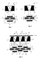
- Fig. 1 is a schematic representation of a top view and a front view of a DC plasma generator according to a first preferred embodiment of the present invention.
- Fig. 2 is a schematic representation of a top view of and of a front view of the same DC plasma generator.
- Fig. 3 illustrates a surface treatment reactor using the DC plasma generator of the first preferred embodiment.
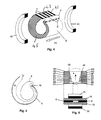
- Fig. 4 is a schematic representation of a perspective view of a DC plasma generator according to a second preferred embodiment of the present invention.
- Fig. 5 is a vertical cross-section of the DC plasma generator of Fig. 4, according to line V-V' in Fig. 4.
- Fig. 6 is a schematic representation of a top view and a front view of a DC plasma generator according to a further embodiment of the present invention.
- FIG. 1 illustrates in diagrammatic form a top view and a front view, respectively, of a first embodiment of a DC plasma generator 2 for generating a non-local, non-equilibrium plasma 4 according to an embodiment of the present invention.
- Fig. 1 principally depicts two electrodes, an anode 6 and a cathode 8, with a wedge-shaped gap 10 between them.
- the centre line 12 of the gap 10 extends along the gap in a direction perpendicular to electric and magnetic fields acting on the gap.
- the cathode 8 is connected to a negative pole of a DC power supply 14
- the anode 6 is connected to a positive pole and electric field I created therebetween.
- a suitable DC voltage is applied between the cathode 8 and the anode 6
- a non-equilibrium plasma 4 is generated between the electrodes 6, 8 which is stabilised by the action of a magnetic filed applied perpendicular to the electric field.
- the plasma which is generated is distributed in the expanding gap 10.
- a “suitable voltage” is meant a potential difference (which is typically between 100 and 5000 Volts), as necessary to create a plasma 4.
- a typical range of suitable electric fields is 1-40Kv/cm, more preferably 2-20kV/cm.
- the voltage to be applied to create the plasma 4 depends on the gas which is present between the electrodes 6, 8, which is to be ionised. Normally air at atmospheric pressure is used, but for surface treatment it may be useful to use other gases, or even gas mixtures.
- the DC plasma generator 2 of the present invention is not limited to a particular kind of gas.
- the electrodes 6, 8 are preferably made of a material with good electrical and thermal conductivity.
- the electrodes 6, 8 may be cooled although for smaller devices with electrodes of good electrical and thermal conductivity such as copper electrodes 6, 8 cooling may not be necessary. Still further improvements in plasma stability may be achieved by making the electrodes 6, 8 from resistive material, i.e. material having a resistivity exceeding 1 x 10 -6 ohm.meter.
- the glow discharge generally starts at that point where the two electrodes 6, 8 are closest to each other, as indicated by the block arrow 16.
- a dielectric layer 18 is provided above and under the electrodes 6, 8 .
- the wedge-shaped gap 10, limited at the upper and under side by the dielectric layers 18 forms a plasma chamber, in which the plasma 4 is generated, and through which the plasma 4 is distributed.
- the dielectric layer 18 may be Pyrex glass or ceramic, or any heat-resilient dielectric material, preferably an inert insulator and may also comprise a laminate, e.g. of a metal layer covered with dielectric material,.
- the dielectric layer 18 may be cooled, for instance, the dielectric layer may be provided by a metal layer covered in a dielectric layer, cooling fluid passing through the metal layer.
- a magnetic field is applied to the plasma 4 e.g. by applying permanent magnets or an electromagnet 20 at the upper and under sides of the electrode/dielectric arrangement.
- the south poles of the permanent magnets or electromagnets 20 are black, and the north poles are white.
- the magnetic field is perpendicular to the electric field, and thus creates a Lorentz action on the moving charged particles in plasma 4, which distributes the plasma along the gap 10, and moves it towards an output opening 22, as represented by the black arrow 24, where it can be used.
- the continuously widening gap will reduce the energy of the plasma until it finally extinguishes. Once the plasma comes beyond the electrodes 6, 8, it will usually extinguish.
- the generation of new plasma channels is continuous and at such a density that one discharge merges into the next thus resulting in a stable plasma of relatively constant properties.
- the plasma is a non-equilibrium plasma, that is a "cold" plasma.
- individual conductive glow discharge channels can no longer be distinguished.
- a typical magnetic field strength range is 0.01T to 1T. It is a surprising aspect of the present invention that useful, stable, distributed, non-equilibrium plasmas can be generated at such low electric and magnetic fields at atmospheric pressure.
- permanent magnets 20 are convenient as no additional power supply is required. For applying higher field strengths electromagnets may be used for applying the magnetic field.
- a gas flow is furthermore introduced into the gap 10 between the electrodes 6, 8, which may be of such a velocity that it exerts a force on the plasma 4, in the same direction as the force exerted by the crossed electric and magnetic fields, which is represented by the black arrow 24.
- the gas flow helps the magnetic field in stabilising the plasma 4. By stabilising is meant that the glow discharge creating the plasma does not deteriorate into an electric arc.
- d 1 2mm
- d 2 10 mm
- ⁇ 10°
- d 3 25 mm
- d 4 1 mm or less (e.g. 0.5 mm)
- d 5 2 mm
- d 2 /d 1 is comprised in the range between 1.5 and 10.
- the angle ⁇ and d 3 are a function of d 2 /d 1 .
- d 4 is smaller than 10 mm.
- the generated non-equilibrium plasma 4 may be used for example for flue gas cleaning in which case an array of plasma generators is preferably used and the flue gas may exit through the gaps 10 of the array.
- the plasma generator in accordance with the present invention may also be used for surface treatment of paper, plastics such as polymers or for textile treatment.
- plastics such as polymers or for textile treatment.
- FIG. 3 An example of an application of the DC plasma generator 2 of Fig. 1 is schematically represented in Fig. 3.
- An array of electrodes 6, 8 is provided. Between each pair of neighbouring electrodes 6, 8, an expanding gap 28, 30, 32 is provided.
- a material 26 to be treated passes next to the electrodes 6, 8, at the widest side of the gap 28, 30, 32.
- Plasma 4 is generated between each pair of neighbouring electrodes 6, 8, as indicated by the block arrow 16.
- the electric field lines in neighbouring gaps 28, 30; 30, 32 present the same direction but a different sense, as each electrode is either an anode 6 or a cathode 8 for two neighbouring gaps 28, 30; 30, 32.
- Permanent magnets 34, 36, 38 are provided at the upper and under sides of the electrode/dielectric arrangements.
- Plasmas extend beyond the mouths of the gaps 28, 30, 32 and can be used for surface treatment of a material 26 for example.
- the flue gas to be cleaned does not need to pass over the plasma 4 extending from the gaps 28, 30, 32, but the pollutants can be introduced into the gaps 28, 30, 32 and transported through the plasma 4 in order to expose pollutants such as hydrocarbons, e.g. toluene, to the free radicals in the plasma 4.
- a second preferred embodiment of the DC plasma generator 2 according to the present invention is shown in Figs. 4 and 5.
- the anode 6 is formed around a longitudinal axis, and in cross-section, substantially has a helical form.
- the cathode 8 consists substantially of a curved plate, which is located around the anode 6, such that a spatially and helically extending gap 10 is present between the anode 6 and the cathode 8, with the smallest part of the gap 10 positioned at the smallest part of the helical form of the anode 6.
- the gap between the anode and the cathode is segregated into a plurality of open channels 43 by insulating plates 45.
- the anode 6 is connected to a positive pole of a DC power supply (not represented), and the cathode 8 is connected to a negative pole of the power supply. If a suitable voltage is generated between the anode 6 and the cathode 8, a non-equilibrium DC plasma is generated at the level where anode 6 and cathode 8 are closest to each other, as represented by the block arrow 16.
- a magnetic field is applied along the longitudinal axis of the anode 6, e.g. by means of a coil arrangement whereby two coils 40, 42 of a diameter which is larger than the cross-sectional dimension of the anode 6 are positioned in a long axial alignment with the anode 6, and radially outward of both ends of the electrodes 6, 8.
- a stationary magnetic field is established with a highly uniform field magnetisation and direction, the direction of the magnetic field being represented by arrow 44.
- the crossed electrical and magnetic fields thus obtained, create a force on the plasma particles generated, which distributes the plasma in the direction of the centre line 12 of the gap 10 as shown in Fig. 5.
- the plasma is constrained between the plates 45 and is a non-equilibrium, non-local plasma. Due to the force exerted on it, the plasma will move through the gap 10, and finally exit in the space between the two electrodes 6, 8 in the channels 43.
- the DC plasma generator 2 described in Figs. 4 and 5 could e.g. be used as a brush, to surface treat plastics materials.
- each of the one-piece electrodes 6, 8 by an array of parallel, equally spaced cylindrical electrodes 6A-6H, 8A-8H as represented in Fig. 6, extending through and supported by supporting members 46. Also other electrode arrangements are possible.
Landscapes
- Physics & Mathematics (AREA)
- Engineering & Computer Science (AREA)
- Plasma & Fusion (AREA)
- Spectroscopy & Molecular Physics (AREA)
- Plasma Technology (AREA)
Abstract
Description
- The present invention relates to the generation of a non-local, non-equilibrium plasma generated at a pressure greater than about 0.5 atmospheres, preferably at atmospheric pressure.
- The term "plasma" is used to identify gaseous complexes which may comprise electrons, positive or negative ions, gaseous atoms and molecules in the ground state or any higher state of excitation including light quanta. The most common method for achieving a plasma state is through an electrical discharge. Electrical discharge plasmas are either "hot", i.e. thermal, or "cold", i.e. non-thermal.
- Hot or thermal plasmas comprise gas atoms and electrons which are essentially in thermal equilibrium with each other. Therefore, hot plasmas are also called "thermal equilibrium plasmas" or "equilibrium plasmas". They are produced from electrical arcs, plasma jets, and magnetic fields. Hot plasmas produced from electrical arcs and plasma jets require equilibrium conditions in which the gas and electron temperatures are very high (5x10³ K) and nearly identical. As a result, most organic molecules and polymers cannot be treated under these conditions because they would be rapidly degraded.
- Cold or non-thermal plasmas, which are not at thermal equilibrium and are therefore also called "non-equilibrium plasmas", comprise gas atoms at a relatively low temperature, room temperature, and electrons at much higher temperatures (several 1000 K). In a cold plasma, the electron mean energy is much higher than the ion and gas mean energies. This plasma state provides an ambient gas temperature along with electrons which have sufficient kinetic energy to cause the cleavage of chemical bonds. As a result, cold plasmas are highly suitable for chemical reactions, such as organic synthesis, polymerizations and surface treatments. Cold plasmas are characterised, typically, by average electron energies of 1-20 electron Volts and electron densities of 109 to 1012 cm-3. Other synonymous terms for cold plasma are "glow discharge" or "low temperature plasma".
- Generally, in order to generate a non-equilibrium plasma, the pressure must be low, of the order of less than 100 torr. When the pressure is increased, the glow discharge becomes an arc discharge and thus the cold plasma becomes a hot plasma. The two types of discharge are distinguished by their electrical characteristics and their mode of operation. A glow discharge operates at high voltage and low currents, while an arc discharge operates at low voltage and high currents. As the current is increased for a glow discharge, the discharge tends to cover more and more of the available cathode area until at some point the current density exceeds a critical value and the discharge suddenly becomes an arc. When this occurs, there is an abrupt drop in voltage and an increase in current. In the glow discharge, electrons are produced in the gas phase by ionization of neutral species by electrons accelerated by the electric field; in the arc discharge, the electrons are produced by copious emission of electrons from a hot cathode. Generally, the electrodes are not consumed in a glow discharge; while in an arc discharge, the cathode is consumed and must be replace frequently.
- The use of a low-pressure plasma has the disadvantage that high priced vacuum chambers and pumping systems are needed. This may still be attractive for certain applications, e.g. in gas lasers. Use of a plasma at approximately ambient atmospheric pressure would not require that any article to be treated is held under vacuum, thereby significantly reducing processing costs. It furthermore removes the requirement that the article to be treated must be capable of surviving under reduced pressure. For many industrial processes, e.g. flue gas cleaning with the aid of plasma, it is necessary to use a plasma at atmospheric pressure.
- It is generally so that, because of atmospheric pressure operation, ions do not survive for a sufficiently long distance beyond the active plasma discharge to bombard a workpiece, unlike low-pressure plasma sources and conventional plasma processing methods. Therefore, stabilisation of the plasma beam is necessary in order for it to be useful.
- It is known from US-5,405,514 to stabilise a glow discharge DC plasma beam at atmospheric pressure by means of a swirling gas stream. Therefore, a first and a second opposing electrode are provided within a glow discharge chamber, and a DC power is applied between the two electrodes. Gas or vapour is passed in a swirling pathway to form a vortex between the electrodes and around the generated plasma beam.
- It is also known from S. Pellerin et al., "Determination of the electrical parameters of a bi-dimensional d.c. Glidearc", Appl. Phys. 32 (1999) 891-897, to use a gas flow and horn-shaped electrodes to generate a gliding arc. Here, a high-pressure, non-equilibrium cold plasma is generated by applying a high DC voltage between two electrodes. An electric arc discharge is created at the narrowest electrode gap, and then the arc string is pushed towards the top of the electrodes by a transverse gas flow.
- Stabilisation of high-pressure glow discharges by a fast gas flow is an established technique. However, for some applications, e.g. surface treatment, the needed flow rates are impracticably high.
- US-5,369,336 discloses a plasma generating device in which glow discharges are generated in a gas containing helium as the main ingredient under atmospheric pressure by means of an AC voltage applied between two concentric electrodes disposed as concentric cylinders. A magnetic field, generated by a permanent magnet provided on a straight extension line from the axis of the concentric electrodes, acts on the plasma and draws it out of the discharging space between the concentric electrodes, for using it for substrate treatment. The use of an AC voltage for generating the plasma is a disadvantage, as this requires a large and expensive power supply. If a plasma is generated using radio frequencies, impedance matching between the plasma and the radio frequency generator is needed, which is not easy to obtain.
- It is known from US-4,755,999 to generate a cold plasma by DC at the very low pressures generally used in a laser apparatus, thus at pressures in the range of 1 to 10 kPa. The generated plasma is moved by a magnetic field, which exerts a force on the discharge. It is furthermore known from C.E. Capjack et al., "Magnetic laser discharge stabilization scaling to high-pressure systems", Journal of Applied Physics 70(11), 1 December 1991, that the required magnetic field strength for stabilisation of laser discharges scales as the square of the pressure. From application of this square law, it would be impractical to try and stabilise a cold DC plasma at atmospheric pressure (100 kPa) by means of a magnetic field, because of the large magnetic field strengths that would be required.
- It is nevertheless an object of the present invention to provide a method and a device for generating and stabilising a non-local, non- equilibrium plasma at high pressure, the plasma being generated by a DC field. By a non-local plasma is meant a spatially distributed plasma, i.e. a plasma which is extended over a space.
- The above objective is accomplished by a DC plasma generator for generating a non-local, non-equilibrium plasma at a pressure greater than about 0.5 atmospheres, comprising two electrodes, a DC voltage generator for generating a DC voltage between the two electrodes, thus creating a DC electric field between the electrodes, and a magnetic field generator for generating a magnetic field perpendicular to the electric field, the crossed electric and magnetic fields distributing the plasma. Preferably the plasma is created at a pressure between 0.5 and 2 atmospheres, and more preferred under atmospheric pressure. The use of a DC voltage enables use of a simpler power supply with less interference compared to an AC voltage generator, thus decreasing the cost of the power supply. Furthermore, using a DC voltage makes the DC plasma generator much more scalable and reduces electromagnetic radiation emission problems. Preferably, the magnetic filed is not an oscillating field, i.e. a unidirectional filed.
- The electrodes may be made of copper or of any conductive material. Magnets used may comprise ferrite, with a surface magnetic field of 0.15 T, or ceramic magnets or where appropriate, electromagnets.
- According to a preferred embodiment, the electrodes of the DC plasma generator are disposed such that there is an expanding gap between them. This gap has a centre line lying in the direction of expansion of the gap, which is perpendicular to both the direction of the electric field and the direction of the magnetic field. The expanding gap allows the plasma to be distributed by the magnetic field in a stable manner.
- According to another preferred embodiment, the DC plasma generator furthermore comprises at least one gas inlet tube for creating a gas flow between the two electrodes in order to assist the magnetic field in distributing the plasma. The gas flow may be a straight flow in the direction of the centre line of the gap, or a vortex flow surrounding the generated non-equilibrium plasma.
- A method for generating and stabilising a non-local, non-equilibrium plasma at a pressure greater than about 0.5 atmosphere is also provided. It comprises the steps of generating a non-equilibrium plasma between two electrodes between which an electric DC field is applied, generating a magnetic field in a direction perpendicular to the electric field, and distributing the plasma by the use of the crossed electric and magnetic fields.
- Other features and advantages of the present invention will become apparent from the following detailed description, taken in conjunction with the accompanying drawings, which illustrate, by way of example, the principles of the invention.
- Fig. 1 is a schematic representation of a top view and a front view of a DC plasma generator according to a first preferred embodiment of the present invention.
- Fig. 2 is a schematic representation of a top view of and of a front view of the same DC plasma generator.
- Fig. 3 illustrates a surface treatment reactor using the DC plasma generator of the first preferred embodiment.
- Fig. 4 is a schematic representation of a perspective view of a DC plasma generator according to a second preferred embodiment of the present invention.
- Fig. 5 is a vertical cross-section of the DC plasma generator of Fig. 4, according to line V-V' in Fig. 4.
- Fig. 6 is a schematic representation of a top view and a front view of a DC plasma generator according to a further embodiment of the present invention.
- Same objects bear the same reference numbers throughout the different drawings.
- The present invention will be described with reference to certain drawings and embodiments but the present invention is not limited thereto but only by the claims.
- Turning now to the drawings Fig. 1, illustrates in diagrammatic form a top view and a front view, respectively, of a first embodiment of a
DC plasma generator 2 for generating a non-local,non-equilibrium plasma 4 according to an embodiment of the present invention. - Fig. 1 principally depicts two electrodes, an
anode 6 and acathode 8, with a wedge-shapedgap 10 between them. Thecentre line 12 of thegap 10 extends along the gap in a direction perpendicular to electric and magnetic fields acting on the gap. When thecathode 8 is connected to a negative pole of aDC power supply 14, theanode 6 is connected to a positive pole and electric field I created therebetween. When a suitable DC voltage is applied between thecathode 8 and theanode 6, anon-equilibrium plasma 4 is generated between theelectrodes gap 10. It is therefore described as non-local, or non-localised or distributed. With a "suitable voltage" is meant a potential difference (which is typically between 100 and 5000 Volts), as necessary to create aplasma 4. A typical range of suitable electric fields is 1-40Kv/cm, more preferably 2-20kV/cm. The voltage to be applied to create theplasma 4 depends on the gas which is present between theelectrodes DC plasma generator 2 of the present invention is not limited to a particular kind of gas. - Once a plasma beam is generated, a current of about 10 mA, typically between 5 and 30 mA, flows trough the
electrodes electrodes electrodes copper electrodes electrodes - The glow discharge generally starts at that point where the two
electrodes block arrow 16. - As represented in the front view, above and under the
electrodes 6, 8 adielectric layer 18 is provided. The wedge-shapedgap 10, limited at the upper and under side by thedielectric layers 18 forms a plasma chamber, in which theplasma 4 is generated, and through which theplasma 4 is distributed. Thedielectric layer 18 may be Pyrex glass or ceramic, or any heat-resilient dielectric material, preferably an inert insulator and may also comprise a laminate, e.g. of a metal layer covered with dielectric material,. Optionally, thedielectric layer 18 may be cooled, for instance, the dielectric layer may be provided by a metal layer covered in a dielectric layer, cooling fluid passing through the metal layer. - A magnetic field is applied to the
plasma 4 e.g. by applying permanent magnets or anelectromagnet 20 at the upper and under sides of the electrode/dielectric arrangement. In the embodiment represented in Fig. 1, the south poles of the permanent magnets orelectromagnets 20 are black, and the north poles are white. The magnetic field is perpendicular to the electric field, and thus creates a Lorentz action on the moving charged particles inplasma 4, which distributes the plasma along thegap 10, and moves it towards anoutput opening 22, as represented by theblack arrow 24, where it can be used. The continuously widening gap will reduce the energy of the plasma until it finally extinguishes. Once the plasma comes beyond theelectrodes - The use of
permanent magnets 20 is convenient as no additional power supply is required. For applying higher field strengths electromagnets may be used for applying the magnetic field. - According to a preferred embodiment, a gas flow is furthermore introduced into the
gap 10 between theelectrodes plasma 4, in the same direction as the force exerted by the crossed electric and magnetic fields, which is represented by theblack arrow 24. The gas flow helps the magnetic field in stabilising theplasma 4. By stabilising is meant that the glow discharge creating the plasma does not deteriorate into an electric arc. - Possible dimensions of the parts of the
plasma generator 2 of Fig. 1 are represented in Fig. 2. For example, d1 = 2mm, d2 = 10 mm, α = 10°, d3 = 25 mm, d4 = 1 mm or less (e.g. 0.5 mm) and d5 = 2 mm. d2/d1 is comprised in the range between 1.5 and 10. The angle α and d3 are a function of d2/d1. d4 is smaller than 10 mm. - The generated
non-equilibrium plasma 4 may be used for example for flue gas cleaning in which case an array of plasma generators is preferably used and the flue gas may exit through thegaps 10 of the array. The plasma generator in accordance with the present invention may also be used for surface treatment of paper, plastics such as polymers or for textile treatment. For surface treatment of paper, polymers or for textile treatment, it is important to have aplasma 4 which extends beyond theelectrodes electrodes electrodes plasma 4 pushed by the magnetic field into the region beyond theelectrode gap 10 which is used for the surface treatment. - An example of an application of the
DC plasma generator 2 of Fig. 1 is schematically represented in Fig. 3. An array ofelectrodes neighbouring electrodes gap electrodes gap Plasma 4 is generated between each pair ofneighbouring electrodes block arrow 16. The electric field lines in neighbouringgaps anode 6 or acathode 8 for twoneighbouring gaps Permanent magnets plasma 4, generated by the crossed electric and magnetic fields, work in the same directions, i.e. towards the wider mouth of the gaps 28-32. Therefore, the north and south poles of thepermanent magnets 36 are reversed for eachgap 30 as the electric field reverse directions in adjacent gaps 28-32. Plasmas extend beyond the mouths of thegaps material 26 for example. For flue gas cleaning, the flue gas to be cleaned does not need to pass over theplasma 4 extending from thegaps gaps plasma 4 in order to expose pollutants such as hydrocarbons, e.g. toluene, to the free radicals in theplasma 4. - A second preferred embodiment of the
DC plasma generator 2 according to the present invention is shown in Figs. 4 and 5. Theanode 6 is formed around a longitudinal axis, and in cross-section, substantially has a helical form. Thecathode 8 consists substantially of a curved plate, which is located around theanode 6, such that a spatially and helically extendinggap 10 is present between theanode 6 and thecathode 8, with the smallest part of thegap 10 positioned at the smallest part of the helical form of theanode 6. The gap between the anode and the cathode is segregated into a plurality ofopen channels 43 by insulatingplates 45. Theanode 6 is connected to a positive pole of a DC power supply (not represented), and thecathode 8 is connected to a negative pole of the power supply. If a suitable voltage is generated between theanode 6 and thecathode 8, a non-equilibrium DC plasma is generated at the level whereanode 6 andcathode 8 are closest to each other, as represented by theblock arrow 16. A magnetic field is applied along the longitudinal axis of theanode 6, e.g. by means of a coil arrangement whereby twocoils anode 6 are positioned in a long axial alignment with theanode 6, and radially outward of both ends of theelectrodes arrow 44. The crossed electrical and magnetic fields thus obtained, create a force on the plasma particles generated, which distributes the plasma in the direction of thecentre line 12 of thegap 10 as shown in Fig. 5. The plasma is constrained between theplates 45 and is a non-equilibrium, non-local plasma. Due to the force exerted on it, the plasma will move through thegap 10, and finally exit in the space between the twoelectrodes channels 43. TheDC plasma generator 2 described in Figs. 4 and 5 could e.g. be used as a brush, to surface treat plastics materials. - While the invention has been shown and described with reference to preferred embodiments, it will be understood by those skilled in the art that various changes or modifications in form and detail may be made without departing from the scope and spirit of this invention. More particularly it is possible to replace each of the one-
piece electrodes cylindrical electrodes 6A-6H, 8A-8H as represented in Fig. 6, extending through and supported by supportingmembers 46. Also other electrode arrangements are possible.
Claims (12)
- Plasma generator (2) for generating a non-local, non-equilibrium plasma (4) at a pressure greater than about 0.5 atmospheres, comprising:two electrodes (6, 8) with a gap (10) therebetween,a DC voltage generator (14) for generating a DC voltage between the two electrodes (6, 8), thus creating an electric field in the gap (10) between the electrodes (6, 8), anda magnetic field generator (20) for generating a magnetic field in the gap perpendicular to the electric field for distributing the plasma (4) between the electrodes (6, 8) along the gap (10), the gap being substantially perpendicular to both the direction of the electric field and the direction of the magnetic field.
- Plasma generator (2) according to claim 1, wherein the electrodes (6, 8) are disposed such that there is an expanding gap (10) between them, the direction of expansion of the gap being substantially perpendicular to both the direction of the electric field and the direction of the magnetic field.
- Plasma generator (2) according to claims 1 or 2, further comprising at least one gas inlet tube for creating a gas flow between the two electrodes (6, 8) for further distributing the plasma (4).
- Plasma generator according to any of the claims, 1 to 3, wherein the electric field between the electrodes is in the range 1-40kV/cm.
- Plasma generator according to any previous claim, wherein the magnetic field in the gap between the electrodes is in the range 0.01T to 1T.
- An array of plasma generators, each plasma generator being in accordance with any one of the claims 1 to 5.
- Method for generating and stabilising a non-local, non-equilibrium plasma at a pressure greater than about 0.5 atmospheres, comprising the steps of:generating a non-equilibrium plasma in a gap between two electrodes between which a DC electric field is applied,generating a magnetic field in the gap perpendicularly to the electric field, anddistributing the plasma by the crossed electric and magnetic fields along the gap, the direction of the gap being substantially perpendicular to both the direction of the electric field and the direction of the magnetic field.
- Method according to claim 7, wherein the plasma is furthermore distributed by applying a gas flow to the plasma.
- Method according to claim, 7 or 8, wherein the electric field between the electrodes is in the range 1-40kV/cm.
- Method according to any of the claims 7 to 9, wherein the magnetic field in the gap between the electrodes is in the range 0.01T to 1T.
- Use of the plasma generator in accordance with any of the claims 1 to 6 in flue gas cleaning.
- Use of the plasma generator in accordance with any of the claims 1 to 6 in surface treatment of plastic, paper or textile materials.
Priority Applications (4)
| Application Number | Priority Date | Filing Date | Title |
|---|---|---|---|
| EP00115997A EP1176857A1 (en) | 2000-07-26 | 2000-07-26 | DC plasma generator for generation of a non-local, non-equilibrium plasma at high pressure |
| AU2001272560A AU2001272560A1 (en) | 2000-07-26 | 2001-07-26 | Dc plasma generator for generation of a non-local, non-equilibrium plasma at high pressure |
| PCT/EP2001/008647 WO2002009482A1 (en) | 2000-07-26 | 2001-07-26 | Dc plasma generator for generation of a non-local, non-equilibrium plasma at high pressure |
| EP01951703A EP1304021A1 (en) | 2000-07-26 | 2001-07-26 | Dc plasma generator for generation of a non-local, non-equilibrium plasma at high pressure |
Applications Claiming Priority (1)
| Application Number | Priority Date | Filing Date | Title |
|---|---|---|---|
| EP00115997A EP1176857A1 (en) | 2000-07-26 | 2000-07-26 | DC plasma generator for generation of a non-local, non-equilibrium plasma at high pressure |
Publications (1)
| Publication Number | Publication Date |
|---|---|
| EP1176857A1 true EP1176857A1 (en) | 2002-01-30 |
Family
ID=8169343
Family Applications (2)
| Application Number | Title | Priority Date | Filing Date |
|---|---|---|---|
| EP00115997A Withdrawn EP1176857A1 (en) | 2000-07-26 | 2000-07-26 | DC plasma generator for generation of a non-local, non-equilibrium plasma at high pressure |
| EP01951703A Withdrawn EP1304021A1 (en) | 2000-07-26 | 2001-07-26 | Dc plasma generator for generation of a non-local, non-equilibrium plasma at high pressure |
Family Applications After (1)
| Application Number | Title | Priority Date | Filing Date |
|---|---|---|---|
| EP01951703A Withdrawn EP1304021A1 (en) | 2000-07-26 | 2001-07-26 | Dc plasma generator for generation of a non-local, non-equilibrium plasma at high pressure |
Country Status (3)
| Country | Link |
|---|---|
| EP (2) | EP1176857A1 (en) |
| AU (1) | AU2001272560A1 (en) |
| WO (1) | WO2002009482A1 (en) |
Cited By (1)
| Publication number | Priority date | Publication date | Assignee | Title |
|---|---|---|---|---|
| CN103906335A (en) * | 2014-04-09 | 2014-07-02 | 中国科学院空间科学与应用研究中心 | Generator of space plasma |
Citations (6)
| Publication number | Priority date | Publication date | Assignee | Title |
|---|---|---|---|---|
| US4071334A (en) * | 1974-08-29 | 1978-01-31 | Maxwell Laboratories, Inc. | Method and apparatus for precipitating particles from a gaseous effluent |
| FR2665454A1 (en) * | 1990-08-01 | 1992-02-07 | Elf Aquitaine | PROCESS FOR DEPOSITING A THIN TRANSPARENT AND ANTISTATIC FILM ON THE STYRENE POLYMER SURFACE OF A SHAPED OBJECT. |
| JPH05263213A (en) * | 1992-03-16 | 1993-10-12 | Matsushita Electric Ind Co Ltd | Hot plasma generating method and film forming device |
| JPH06247715A (en) * | 1993-02-19 | 1994-09-06 | Nippon Steel Corp | Production of oxide superconducting thin film |
| JPH0848510A (en) * | 1994-08-04 | 1996-02-20 | Satoru Mieno | Fullerene automatic synthesizer by arc discharge |
| US5861630A (en) * | 1997-11-22 | 1999-01-19 | Becker; Richard L. | Method for generating a boron vapor |
-
2000
- 2000-07-26 EP EP00115997A patent/EP1176857A1/en not_active Withdrawn
-
2001
- 2001-07-26 AU AU2001272560A patent/AU2001272560A1/en not_active Abandoned
- 2001-07-26 EP EP01951703A patent/EP1304021A1/en not_active Withdrawn
- 2001-07-26 WO PCT/EP2001/008647 patent/WO2002009482A1/en not_active Ceased
Patent Citations (6)
| Publication number | Priority date | Publication date | Assignee | Title |
|---|---|---|---|---|
| US4071334A (en) * | 1974-08-29 | 1978-01-31 | Maxwell Laboratories, Inc. | Method and apparatus for precipitating particles from a gaseous effluent |
| FR2665454A1 (en) * | 1990-08-01 | 1992-02-07 | Elf Aquitaine | PROCESS FOR DEPOSITING A THIN TRANSPARENT AND ANTISTATIC FILM ON THE STYRENE POLYMER SURFACE OF A SHAPED OBJECT. |
| JPH05263213A (en) * | 1992-03-16 | 1993-10-12 | Matsushita Electric Ind Co Ltd | Hot plasma generating method and film forming device |
| JPH06247715A (en) * | 1993-02-19 | 1994-09-06 | Nippon Steel Corp | Production of oxide superconducting thin film |
| JPH0848510A (en) * | 1994-08-04 | 1996-02-20 | Satoru Mieno | Fullerene automatic synthesizer by arc discharge |
| US5861630A (en) * | 1997-11-22 | 1999-01-19 | Becker; Richard L. | Method for generating a boron vapor |
Non-Patent Citations (4)
| Title |
|---|
| DATABASE WPI Section Ch Week 199440, Derwent World Patents Index; Class L03, AN 1994-321967, XP002154959 * |
| KYOICHI KURIKI ET AL: "MAGNETOSONIC CONDITION IN MAGNETOPLASMADYNAMIC FLOW", JOURNAL OF PROPULSION AND POWER,US,AMERICAN INSTITUTE OF AERONAUTICS AND ASTRONAUTICS. NEW YORK, vol. 8, no. 6, 1 November 1992 (1992-11-01), pages 1208 - 1211, XP000320933, ISSN: 0748-4658 * |
| PATENT ABSTRACTS OF JAPAN vol. 018, no. 040 (C - 1155) 21 January 1994 (1994-01-21) * |
| PATENT ABSTRACTS OF JAPAN vol. 1996, no. 06 28 June 1996 (1996-06-28) * |
Cited By (1)
| Publication number | Priority date | Publication date | Assignee | Title |
|---|---|---|---|---|
| CN103906335A (en) * | 2014-04-09 | 2014-07-02 | 中国科学院空间科学与应用研究中心 | Generator of space plasma |
Also Published As
| Publication number | Publication date |
|---|---|
| WO2002009482A1 (en) | 2002-01-31 |
| AU2001272560A1 (en) | 2002-02-05 |
| EP1304021A1 (en) | 2003-04-23 |
Similar Documents
| Publication | Publication Date | Title |
|---|---|---|
| US6262523B1 (en) | Large area atmospheric-pressure plasma jet | |
| US5872426A (en) | Glow plasma discharge device having electrode covered with perforated dielectric | |
| US6147452A (en) | AC glow plasma discharge device having an electrode covered with apertured dielectric | |
| JP2648235B2 (en) | Ion gun | |
| US5414324A (en) | One atmosphere, uniform glow discharge plasma | |
| US7327089B2 (en) | Beam plasma source | |
| US7116054B2 (en) | High-efficient ion source with improved magnetic field | |
| US5243169A (en) | Multiple torch type plasma generation device and method of generating plasma using the same | |
| WO1998042002A9 (en) | Glow plasma discharge device | |
| US20140178604A1 (en) | Dual-Zone, Atmospheric-Pressure Plasma Reactor for Materials Processing | |
| US6900592B2 (en) | Method and apparatus for stabilizing of the glow plasma discharges | |
| EP0741404A1 (en) | A method and an electrode system for excitation of a plasma | |
| KR20000017070A (en) | Toroidal filament for plasma generation | |
| WO2002009482A1 (en) | Dc plasma generator for generation of a non-local, non-equilibrium plasma at high pressure | |
| US6879103B1 (en) | Glow plasma discharge device | |
| CA1259396A (en) | Laser apparatus utilizing a magnetically enhanced electrical discharge | |
| AU581516B2 (en) | Plasma generator | |
| AU602109B2 (en) | Improvements in plasma generators | |
| Jiang et al. | Study on a novel high-pressure micro-discharge configuration for micro-laser | |
| Chao et al. | Study on a novel high-pressure micro-discharge configuration for micro-laser | |
| Liu et al. | Design aspects of a compact, single-frequency, permanent magnet ECR ion source with a large uniformly distributed resonant plasma volume | |
| HK1029222B (en) | Glow plasma discharge device |
Legal Events
| Date | Code | Title | Description |
|---|---|---|---|
| PUAI | Public reference made under article 153(3) epc to a published international application that has entered the european phase |
Free format text: ORIGINAL CODE: 0009012 |
|
| AK | Designated contracting states |
Kind code of ref document: A1 Designated state(s): AT BE CH CY DE DK ES FI FR GB GR IE IT LI LU MC NL PT SE Kind code of ref document: A1 Designated state(s): BE |
|
| AX | Request for extension of the european patent |
Free format text: AL;LT;LV;MK;RO;SI |
|
| AKX | Designation fees paid |
Free format text: BE |
|
| REG | Reference to a national code |
Ref country code: DE Ref legal event code: 8566 |
|
| STAA | Information on the status of an ep patent application or granted ep patent |
Free format text: STATUS: THE APPLICATION IS DEEMED TO BE WITHDRAWN |
|
| 18D | Application deemed to be withdrawn |
Effective date: 20020731 |