EP1176499A1 - Track ball device and electronic apparatus comprising the same - Google Patents
Track ball device and electronic apparatus comprising the same Download PDFInfo
- Publication number
- EP1176499A1 EP1176499A1 EP01902779A EP01902779A EP1176499A1 EP 1176499 A1 EP1176499 A1 EP 1176499A1 EP 01902779 A EP01902779 A EP 01902779A EP 01902779 A EP01902779 A EP 01902779A EP 1176499 A1 EP1176499 A1 EP 1176499A1
- Authority
- EP
- European Patent Office
- Prior art keywords
- ball device
- roller
- rollers
- track ball
- ball
- Prior art date
- Legal status (The legal status is an assumption and is not a legal conclusion. Google has not performed a legal analysis and makes no representation as to the accuracy of the status listed.)
- Granted
Links
Images























Classifications
-
- G—PHYSICS
- G06—COMPUTING OR CALCULATING; COUNTING
- G06F—ELECTRIC DIGITAL DATA PROCESSING
- G06F3/00—Input arrangements for transferring data to be processed into a form capable of being handled by the computer; Output arrangements for transferring data from processing unit to output unit, e.g. interface arrangements
- G06F3/01—Input arrangements or combined input and output arrangements for interaction between user and computer
- G06F3/03—Arrangements for converting the position or the displacement of a member into a coded form
- G06F3/033—Pointing devices displaced or positioned by the user, e.g. mice, trackballs, pens or joysticks; Accessories therefor
- G06F3/0354—Pointing devices displaced or positioned by the user, e.g. mice, trackballs, pens or joysticks; Accessories therefor with detection of two-dimensional [2D] relative movements between the device, or an operating part thereof, and a plane or surface, e.g. 2D mice, trackballs, pens or pucks
-
- G—PHYSICS
- G06—COMPUTING OR CALCULATING; COUNTING
- G06F—ELECTRIC DIGITAL DATA PROCESSING
- G06F3/00—Input arrangements for transferring data to be processed into a form capable of being handled by the computer; Output arrangements for transferring data from processing unit to output unit, e.g. interface arrangements
- G06F3/01—Input arrangements or combined input and output arrangements for interaction between user and computer
- G06F3/03—Arrangements for converting the position or the displacement of a member into a coded form
- G06F3/033—Pointing devices displaced or positioned by the user, e.g. mice, trackballs, pens or joysticks; Accessories therefor
- G06F3/0354—Pointing devices displaced or positioned by the user, e.g. mice, trackballs, pens or joysticks; Accessories therefor with detection of two-dimensional [2D] relative movements between the device, or an operating part thereof, and a plane or surface, e.g. 2D mice, trackballs, pens or pucks
- G06F3/03549—Trackballs
-
- G—PHYSICS
- G06—COMPUTING OR CALCULATING; COUNTING
- G06F—ELECTRIC DIGITAL DATA PROCESSING
- G06F3/00—Input arrangements for transferring data to be processed into a form capable of being handled by the computer; Output arrangements for transferring data from processing unit to output unit, e.g. interface arrangements
- G06F3/01—Input arrangements or combined input and output arrangements for interaction between user and computer
- G06F3/03—Arrangements for converting the position or the displacement of a member into a coded form
- G06F3/0304—Detection arrangements using opto-electronic means
- G06F3/0312—Detection arrangements using opto-electronic means for tracking the rotation of a spherical or circular member, e.g. optical rotary encoders used in mice or trackballs using a tracking ball or in mouse scroll wheels
Definitions
- the track ball device disclosed in Japanese Laid-open Patent No.8-185259 is known.
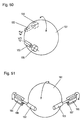
- This track ball device as shown in Fig. 51, has rotary blades 164, 165 and stoppers 166, 167 mounted on rollers 162, 163, give a click feel to an operator manipulating the ball 161.
- This track ball device for generating the click feel, has a rotary torque of the rollers 162, 163 increase because of a hooking engagement of the rotary blades 164, 165 and the stoppers 166, 167.
- a larger rotary torque is accordingly transmitted at an area where the ball 161 and the rollers 162 contacts, 163, i.e., a portion for transmitting a rotation of the ball 161 to the rollers 162, 163.
- the ball is likely to slip on the friction surface of this contacting area, and a clear click feel may not be generated.
- this device since being composed of many constituent members, has a size reduced hardly and has a cost lowered hardly.
- the section of the portion of the rollers contacting and supporting the ball is a circular sawtooth profile, and the directions of sawtooth serrations of the confronting rollers are reverse to each other.
- Each roller is provided with a rotation-amount-detecting unit.
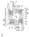
- Fig. 1 is a plan view of a track ball device having a case excluded according to embodiment 1 of the present invention
- Fig. 2 is a perspective outline view of the device.
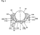
- Fig. 3 to Fig. 5 are sectional views at cut lines in Fig. 1 of the track ball device having the case, and specifically Fig. 3 is a sectional view at a line P-O-P, Fig. 4 is a sectional view at a line Q-O-Q, and Fig. 5 is a sectional view at a line R-O-R.
- the pressure of elastic leg 309B pushing the XI roller 302 is small.
- the own weight of the ball 308 pushing the XI roller 302 and a pressure for rotating the ball 308 widens the interval against the XII roller 303.
- the ball 308 contacts securely with four rollers including the YI roller 304 and YII roller 305 crossing in orthogonal to the rollers 302, 301.
- ratchet gears 302C to 305C having sawtooth serrations 302B to 305B are disposed at four positions at 90-degree intervals on the circumference, respectively.
- the serrations 304B, 305B, and ratchet gears 304C, 305C are not shown.
- Arresting ratchets 302D to 305D made of a thin elastic metal extending from the base unit 301 elastically contact with the serrations 302B to 305B, respectively.
- the directions of the sawtooth serrations 302B to 305B are opposite between the confronting XI roller 302 and XII roller 303, and are also opposite between the confronting YI roller 304 and YII roller 305.
- the gears and arresting ratchets form rotating-direction-regulating portions 302E to 305E for allowing the confronting rollers to rotate only in the mutually opposite directions, respectively.
- the ball 308 upon being rotated has the arresting ratchet 302D elastically contacting with the sawtooth serration 302B of the ratchet gear 302C climb up along a slope on the serration 302B.
- the arresting ratchet 302D upon falling at a step difference between the leading end and root of the serration 302B, generates a clear click feel.
- the ball 308, upon being rotated, has the arresting ratchet 303D have to run over the step difference between the root of the serration 303B of the gear 303C and the leading end of the adjacent serration.
- the XII roller 303 having the gear 303C is regulated for not rotating by the arresting ratchet 303D, which cannot run over the step difference.
- rotary movable contacts 310 to 313 are disposed, respectively.
- Elastic fixed contacts 314 to 317 made of thin elastic metal plates extending in pair from the base unit 301 elastically contact with the movable contacts 310 to 313, thus forming rotary switches 318 to 321, which are rotation-amount-detecting units of the rollers.
- Fig. 7 is a perspective outline view of the contact of the rotary switch.
- the elastic fixed contacts 314 to 317 elastically contact with circular rings 310A to 313A of the rotary movable contacts 310 to 313 and comb serrations 310B to 313B conducting to the movable contacts.
- the elastic fixed contact 314 has contact points 314A and 314B.
- the contacts 315 to 317 have two contact points each 315A to 317B.
- the rollers 302 to 305 upon rotating, electrically open and close each pair of elastic fixed contacts (314A, 314B) to (317A, 317B), which generate signals.
- the comb serrations 310B to 313B of the rotary movable contacts 310 to 313 are provided in four, i.e., the same number as the sawtooth serrations 302B to 305B of the ratchet gears 302C to 305C.
- the serrations 310B to 313B are disposed at a specified angle to the serrations 302B to 305B, respectively, to generate a signal synchronized with a click feel.
- a flexible connection board (not shown) disposed at the lower side of the base unit 301 may be also connected to the circuit board.
- the output terminals 319A to 320B are connected securely. Even if the base unit 301 rotates against the circuit board, the connection board follows the unit, and the connection is maintained.
- a case 322 and a lid plate 323 made of resin cover the track ball device.
- the case 322 is, as shown in Fig. 3 to Fig. 5, composed of a bowl unit 322A which is open at the upper end and is disposed to envelope the lower portion of the ball 308, and a peripheral wall 322B which extends downward from the outer circumference of the upper end and fixed to the base unit 301 at the lower end.
- the bowl unit 322A has four through-holes 322C provided at positions where the central contacting portions 302A to 305A of the rollers 302 to 305 contact with the outer circumference of the ball 308.
- the center of the bowl unit 322A is a dish 322D, which is accommodated in a dent 301A in the center of the base unit 301. Therefore, even if water splashes over the track ball device, the rotary switches 318 to 321 are not affected from it.
- Fig. 8 is a perspective outline view showing a portion where the lid plate and case of the track ball device are coupled.
- the lid plate 322 is, as shown in Fig. 3 to Fig. 5 and Fig. 8, formed like a ring having a circular hole 323A slightly smaller than the diameter of the ball 308.
- Two legs 323C with steps 323B of at the lower side of the lid plate 323 are respectively inserted into two coupling holes 322E at the upper end of the case unit 322.
- the lid plate 323, upon being turned, is detachably coupled with the case 322, thereby preventing the ball 308 from being displaced from the track ball device in an ordinary state.
- the lid plate 323, upon being detached, allows the ball 308 to be replaced.
- rotating direction regulating unitss 302E, 303E composed of ratchet gears 302C, 303C having sawtooth serrations 302B, 303B, and arresting ratchets 302D, 303D elastically contacting therewith are provided.
- the ball 308 in the left direction upon being rotated, makes the arresting ratchet 302D elastically contacting with the serration 302B of the XI roller 302 climb along the slope of the serration 302B. Therefore, the XI roller 302 rotates since the rotary torque transmitted from the ball 308 to the contacting portion 302A gradually increases.
- the arresting ratchet 302D falls at a portion having the step difference from the leading end of the serration 302B to the root of the next serration, and at the moment, generates a click feel. Simultaneously, the transmitted rotary torque decreases gradually. Again, the arresting ratchet 302D climbs up along the slope of the next serration, and then, falls at a the portion having the next step difference, and this operation is repeated.
- the rotation is not transmitted to the XI roller 302 and XII roller 303, but is transmitted to the YI roller 304 or YII roller 305, and the moving distance in the cursor setting direction, that is, a positive or negative direction of the Y-axis is detected.
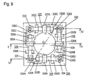
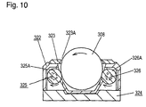
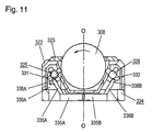
- a track ball device in this embodiment has four circular shaft XI roller 325, XII roller 326, and YI roller 327, YII roller 328 disposed in two sets of two opposing rollers in orthogonal to each other on the top of a square base unit 324 made of resin.
- the base unit 324 has support units 329A to 329D, and support units 330A to 330D formed at two positions for one roller unitarily with the base unit at the same height.
- the rollers are rotatably supported by the support units.
- an operating element, contacting portions 325A to 328A having circular sections contact on the outer circumference of the ball, and support the ball 308 rotatably in all directions on the same plane.
- the lever 336 upon having the leading end 338 thereof pushed down to a specified position, as indicated by dotted line in Fig. 12, rotates about the shaft 337.
- a drive portion 339 below the lever 336 pushes and deforms elastically a movable contact 343 made of a thin elastic metal plate into the switch case 340, and then, makes a contact point 344 contact with a fixed contact 345,thereby short-circuiting between output terminals 346 and 347.
- the lever 336 upon having the pushing force removed, returns to an original state by the elastic restoring force of the movable contact 343.
- the pins contact with the levers 336A and 336B of the switches 335A and 335B disposed on the base unit 324, and form the rotating direction regulating units as mentioned above.
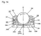
- the ball 308, upon being rotated in the left direction pushes the leading end 338A in a direction departing from the ball 308.
- the lever 336A of the switch 335A rotates with resisting the elastic force, and does not regulate the rotation of the XI roller 325. Therefore, as shown in the sectional view in Fig. 14, since the rotary torque transmitted from the ball 308 to the contacting portion 325A increases, the leading end 338A is pushed down.
- the switch 335A is actuated, and the output terminals 346A, 347A are short-circuited.
- a rotation of the ball 308 in the front-and-back direction is not transmitted to the XI roller 325 and XII roller 326, but is transmitted to the YI roller 327 or YII roller 328, and the moving distance of the cursor in the Y-axis direction is detected.
- the four pins 331 to 334 project radially at one end of the rollers 325 to 328. That is, four signals are generated in one rotation of each one of the rollers 325 to 328, but the number of times can increases or decreases as required.
- the self-resetting switches 335A to 335D of push operation type are driven by the pins 331 to 334 provided in the rollers 325 to 328.
- the rotating direction regulating units and rotation amount detecting units are formed integrally, so that a compact and inexpensive track ball device can be obtained.
- Fig. 17 is a sectional view of a track ball device in embodiment 4 of the invention
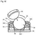
- Fig. 18 and Fig. 19 are sectional views of the operated track ball device.
- the track ball device of this embodiment includes a self-resetting push switch disposed on the base unit 324 for easily supporting the ball 308 rotatably. While not being manipulated, the ball 308 does not contact with contacting portions 325A, 326A, so that gaps 360, 361 can be formed between the ball 308 and the contacting portions 325A, 326A of the rollers 325, 326.
- This track ball device may have a rotating direction regulating unit for rollers.
- the rotating direction regulating unit may be the same as in embodiment 1 or 2, but may has a simple structure as explained above.
- the track ball device since having nothing to impede the rotation of the ball such as the roller having a rotation regulated by the rotating direction regulating unit, is smoothly manipulated device.
- Fig. 20 is a plan view of a track ball device having a case excluded according to embodiment 5 of the invention
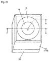
- Fig. 21 is a perspective outline view of the device
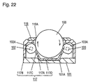
- Fig. 22 is a sectional view at a line P-O-Q of the track ball device in Fig. 21,
- Fig. 23 is a sectional view at a line P-O-R of the track ball device in Fig. 21.
- Each of sections of the contacting portions 102A to 105A of the XI roller 102 to YII roller 105 is a circular sawtooth profile, as shown in Fig. 22 and Fig. 23, having four undulations at intervals of 90 degrees on the circumference.
- the direction of sawtooth is mutually opposite between the confronting XI roller 102 and XII roller 103 as shown in Fig. 22.
- a sawtooth direction between the confronting YI roller 104 and YII roller 105 is similar.
- an elastic leg 109B is disposed in a support recess 109A in the support unit 106A for supporting the XI roller 102.
- the elastic leg 109B applies a light pressure to have the opposing interval of the XI roller 102 and XII roller 103 narrower than a specified interval.
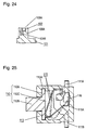
- the switch 111, the rotation amount detecting unit is a thin self-resetting switch of push operation type.
- Fig. 25 is a sectional view of the switch 111 without a cover
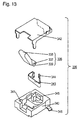
- Fig. 26 is a perspective view of the disassembled switch.
- a support recess 113A and cover 114 provided at the upper end of a switch case 113 rotatably support the shaft 112A of the lever 112.
- the lever 112 rotates about the shaft 112A.
- the case 117 is, as shown in Fig. 22 and Fig. 23, composed of a bowl unit 117A which opens at the upper end and is disposed to envelope the lower portion of the ball 108, and a peripheral wall 117B which extends downward from the outer circumference of the upper end and fixed to the base unit 101 at the lower end.
- the bowl unit 117A has four through-holes 117C provided at positions where the central contacting portions 102A to 105A of the rollers 102 to 105 contact with the outer circumference of the ball 108.
- the center of the bowl unit 117A is a dish 117D, which is accommodated in a dent 101A in the center of the base unit 101. Therefore, even if water splashes over the track ball device, the four switches 111 on the base unit 101 is not affected from the water.
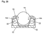
- XII roller 103 Since the contacting portions 102A and 103A of XI roller 102 and XII roller 103 have opposite directions of circular sawtooth serrations, as mentioned above, the XII roller 103 on which the ball 108 climbs along the slope from the recess to the bump of the circular sawtooth section rotates. The rotation is regulated in the XI roller 102 on which the ball 108 must run over a nearly vertical step difference from the recess to the bump of the circular sawtooth section, and the ball 108 idles in the recess at the step.
- the XII roller 103 upon continuing to rotate, makes the next drive pin 110 of the cam 103B similarly turn on and off the switch 111.
- the switch 111 turns on and off four times in synchronism with a click feel during one rotation of the XII roller 103, and the turned on/off is transmitted to a circuit of the electronic apparatus employing the track ball device through the output terminals 111A, 111B.
- the number of rotations of the XII roller 103 i.e., a moving distance of a cursor on a display screen of the electronic apparatus in either positive or negative direction of the X-axis is detected.
- the XII roller 103 is regulated to rotate, while the XI roller 102 is free to rotate.
- the moving distance of the cursor on the display screen in a reverse direction to that for a rotation in the right direction is detected.
- the rotation of the ball is not transmitted to the XI roller 102 and XII roller 103, but is transmitted to the YI roller 104 or YII roller 105, and therefo, the moving distance of the cursor in either positive or negative direction of the Y-axis is detected.
- either XI roller 102 or XII roller 103, and either YI roller 104 or YII roller 105 rotate depending on the XY direction component of the rotation, and the cursor moving distance in each direction of the X-axis and Y-axis is detected.
- the cams 102B to 105B of the XI roller 102 to YII roller 105 of the track ball device have four drive pins 110 at 90-degree intervals. That is, the switch is turned on and off four times in one rotation of each one of the rollers 102 to 105.
- the number of pins, that is, the number of times of turning on and off the switch can increase and decrease as required.
- the contacting portions 102A to 105A of the XI roller 102 to YII roller 105 have a circular sawtooth section.
- Fig. 30 shows a sectional shape of the contacting portion.
- four arcs 119A to 122A formed by deviating the center of the reference circle 123 by a step 124 are overlaid. So as to form the step 124 having a specified dimension between the adjacent arcs at the undulations 119 to 122, the outer circumference of the arcs 119A to 122A is cut off in a specific rotating direction from the center of the rollers 102 to 105.
- the track ball device when having the ball 108 manipulated, generates a click feel, and can move a cursor on a display screen of the electronic apparatus precisely.
- the track ball device moreover, allows the ball 108 to hardly slip between the contacting portions 102A to 105A of the rollers 102 to 105, and thus having a small rotary play angle.
- Fig. 31 is a plan view of a track ball device having a case excluded according to embodiment 6 of the invention
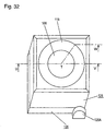
- Fig. 32 is a perspective outline view of the device
- Fig. 33 is a sectional view at a line U-T-V of the track ball device in Fig. 32
- Fig. 34 is a sectional view at a line U-T-W of the track ball device in Fig. 32.
- the track ball device according to embodiment 6 has a base unit 126 rotatably supported by a circuit board 125 of an electronic apparatus employing the device, and has a self-resetting push switch 127 disposed on the circuit board 125 beneath the base unit 126.
- the dome-shaped movable contact 129 has an elastic repulsive force set at a specified value enough to prevent the dome shape from being inverted as being pushed by the protrusion 128B at the lower end of the case 128 in the ordinary operation or during a manipulation of the ball 108.
- the self-resetting push switch 127 may not be required to be formed on the circuit board 125, and may be a single switch mounted on the circuit board 125 with using a push switch having a small height.
- the protrusion 128B contacting with the upper center of the push switch 127 may not be provided on the case 128, but may be provided on the base unit 126.
- the ball 108 an operating element, upon having the upper portion thereof rotated, moves a position of a cursor on a display screen of an electronic apparatus employing the track ball device similarly to embodiment 5, and the explanation is omitted.
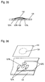
- the dome-shaped movable contact 129 When this pushing force exceeds a specified value, the dome-shaped movable contact 129 is elastically inverted with a click feel, and the lower side of the movable contact 129 contacts with the center of the fixed contact 127B as shown in a sectional view in Fig. 37. As a result, the switch fixed contact 127A and center fixed contact 127B conduct to each other through the dome-shaped movable contact 129.
- the conducting is transmitted to a circuit of the electronic apparatus through the wiring 127C on the circuit board 125, as for example, a signal indicating that a position of the cursor on the display screen is recognized.
- the dome-shaped movable contact 129 of the push switch 127 returns to the original dome shape by the own elastic restoring force, and rotates the base unit 126 in a direction for pushing back the base unit 126 upward through the protrusion 128B, i.e., the case 128. Thereby the device returns to the original ordinary state shown in Fig. 33 and Fig. 34. As a result, the switch fixed contact 127A and the center fixed contact 127B of the push switch 127 open again.
- Fig. 38 is a sectional view of a track ball device according to embodiment 7 of the invention.
- This track ball device is similar to embodiment 6 shown in Fig. 34, except that the member for mounting four switches 131 rotation amount detecting units.
- a top view of the push switch 127 and four switches 131 is the same as in embodiment 6 shown in Fig. 31, and detailed description is omitted.
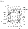
- rollers 134 to 137 rotatably supported by support units 139A to 139D and support units 140A to 140D formed on a base unit 138 have rotary movable contacts 134B to 137B on the outer circumference at one end, respectively.
- the rollers 134 to 137 similarly to those in embodiments 5 to 7, have contacting portions 134A to 137A of circular sawtooth section at the center.
- Fig. 41 is a perspective outline view of a contact point of a rotary switch.
- rotary movable contacts 134B to 137B are composed of circular rings 134C to 137C and comb serrations 134D to 137D projecting therefrom.
- a pair of elastic fixed contacts 142A and 142B elastically contact with the circular ring 134C and comb serration 134D, respectively.
- Each pair of elastic fixed contacts 145A and 145B, elastic fixed contacts 146A and 146B, and elastic fixed contacts 147A and 147B elastically contact with the rotary movable contacts 135B to 137B, respectively.
- the rollers 134 to 137 upon being rotated, makes the elastic fixed contacts 142A to 142D, and 143A to 143D conduct or cut off each other.
- the comb serrations 134D to 137D of the rotary movable contacts 134B to 137B are matched in the number and angular position with the undulations of the contacting portions 134A to 137A of the rollers 134 to 137,respectively.
- the track ball device of embodiment 8 upon employing the rotary switches 144A to 144D having such configuration as the rotation amount detecting units, has a small rotation amount detecting units, and issues a turn on-off signal according to a rotation of the rollers 134 to 137 securely. Further, even when the base unit 138 rotates and pushes the push switch 127, the long arm-shaped elastic fixed contacts 142A to 142D, 143A to 143D follow to the base unit by deflecting, so that switch may not malfunction.
- Fig. 42 is a front sectional view of a track ball device in embodiment 9 of the invention
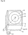
- Fig. 43 is a perspective outline view of the device
- Fig. 44 is a plan view of the device having a case excluded
- Fig. 45 is a sectional view at a line Q-O-Q of the track ball device in Fig. 43.
- a base unit 201 of the track ball device is made of resin in a square shape as seen from the top.
- two cylindrical X roller 202 and Y roller 203 are disposed at right angle to each other in parallel to the sides near the two sides of the square.
- the rollers 202 and 203 are rotatably supported by support units 201A to 201C formed unitarily with the base unit 201.
- a third roller 204 is rotatably held by a support unit 201D.
- the outer circumference located slightly lower than the center of the ball 205, an operating element, contacts with large-diameter contacting portions 202A, 203A, and 204A of the X roller 202, Y roller 203, and third roller 204.
- the contacting portions support the ball 205 rotatably in all directions.
- the outer circumference of the large-diameter contacting portions 202A and 203A of the X roller 202 and Y roller 203 has a circumferential shape, as shown in Fig. 42, Fig. 44, and Fig. 45, having plural linear recesses 206 and 207 disposed on the circumferential surface at a specified angle pitch in parallel to the shaft of the roller.
- the large-diameter contacting portion 204A of the third roller 204 has a smooth circumferential surface.
- the ball 205 stops as being trapped in one of the recesses 206 and 207 on the outer circumference of the large-diameter contacting portions 202A, 203A of the X roller 202 and Y roller 203.
- a movable contact 208 composed of a circular ring 208A and a comb serration 208B is provided on the outer circumference of a medium-diameter shaft 202B which is a circular rotary shaft provided coaxially with the X roller 202.
- the comb serration 208B conducts with the circular ring 208A, and is formed at an angle pitch corresponding to the recess 206 of the large-diameter contacting portion 202A.
- Three elastic legs 209A to 209C having different length from each other of an elastic fixed contact 209 extending from the base unit 201 elastically contact with the movable contact 209, and form an X-rotary encoder 210 which is a rotation amount detecting unit of the X roller 202.
- a movable contact 211 composed of a circular ring 211A and a comb serration 211B is provided on the outer circumference of a circular medium-diameter shaft 203B provided coaxially with the Y roller 203.
- the comb serration 211B conducts with the circular ring 211A, and is formed at an angle pitch corresponding to the recess 207 of the large-diameter contacting portion 203A.
- Three elastic legs 212A to 212C having different lengths from each other of an elastic fixed contact 212 extending from the base unit 201 elastically contact with the movable contact 211, and form a Y-rotary encoder 213 which is a rotation amount detecting unit of the Y roller 203.
- Electric signals generated by the encoders 210, 213 are transmitted to a circuit of an electronic apparatus employing the track ball device through elastic connection terminals 210A to 210C and elastic connection terminals 213A to 213C conducting with the elastic fixed contacts 209 and 212.
- the ball 205 stops as being trapped in the recesses 206 and 207 of the large-diameter contacting portions 202A and 203A.
- the encoders 210 and 213 do not generate electric signals. That is, the connection terminals 210A to 210C and 213A to 213C electrically open.
- the encoders 210 and 213 are disposed on the outer circumference of the medium-diameter shafts 202B, 203B coaxially with the movable contact 208 and rollers 202, 203, and are hence small.
- the track ball device is formed in a compact size.
- the case 214 opens at the upper end, and is composed of a bowl unit 214A for enveloping the lower portion of the ball 205, and a peripheral wall 214B extending downward from the outer circumference of the upper end surface to the lower end fixed to the base unit 201.
- the bowl unit 214A has through-holes 214C disposed at positions of the large-diameter contacting portion 202A of the X roller 202, large-diameter contacting portion 203A of the Y roller 203, and large-diameter contacting portion 204A of the third roller 204, contacting with the outer circumference of the ball 205.
- the center portion 214D is a dish located to face to the center portion of the base unit 201 with a slight clearance. Even if water splashes over this track ball device, the contact points of the X encoder 210 and Y encoder are not practically affected from the water.
- the lid plate 215 is a ring having a circular hole 215A slightly smaller than the diameter of the ball 205 in the center.
- Two legs 215C having a step 215B are inserted into coupling holes 214E at the upper end of the case 214.
- the lid plate 215, upon being rotated, is detachably coupled to the case 214. In the ordinary state, therefore, the ball 205 is prevented from being displaced from the track ball device.
- connection terminals 210A to 210C and connection terminals 213A to 213C of the encoders 210 and 213 are elastically connected to the connection points (not shown), so that soldering or other connecting process is not needed.
- the ball 205 has a contacting area fitting into the recess 206A on the outer circumference of the large-diameter contacting portion 202A escape from the recess 206A, move along the outer circumference, and fits into the next recess 206B, thus generating a click feel at the moment.
- the movable contact 208 of the X rotary type encoder 210 rotates.
- independent pulse signals are generated at the elastic legs 209A to 209C of the elastic fixed contact 209 elastically contacting with the circular ring 208A and comb serration 208B of the contact 208. That is, one pulse signal is generated each between connection terminals 210A and 210B, and between connection terminals 210A and 210C of the elastic legs 209A to 209C.
- the relation between the generated pulse signal and the rotating direction of the movable contact 208, i.e., the X roller 202 is the same as a general rotary type encoder, and the explanation is omitted.
- pulse signals are generated precisely by the number corresponding to the number of clicks between the connection terminals 210A and 210B, and between 210A and 210C.
- the signals are transmitted to the circuit of the electronic apparatus, and moves a cursor on a display screen in an X-direction precisely in response to the rotation amount.
- the ball 205 When being rotated in a right direction, the ball 205 rotates on a contacting portion where the outer circumference of the ball 205 fits into the recess 207 on the outer circumference of the large-diameter contacting portion 203A of the Y roller 203, and thus, does not rotate the Y roller 203.
- the X roller 202 rotates in a reverse direction of the above rotation while generating a click feel, and the X-rotary encoder 210 generates pulse signals of which number corresponds to the number of clicks.
- the Y roller 203 rotates and generates click feels.
- the third roller 204 rotates together with the X roller 202 and Y roller 203, thereby supporting the ball 205 which thus can rotate smoothly.
- the outer circumference of the large-diameter contacting portions 202A and 203A of the X roller 202 and Y roller 203 have a circumferential shape having undulations. Therefore, according to the necessity of manipulation in the electronic apparatus using the track ball device, undulations may be formed on the outer circumference of either the X roller 202 or Y roller 203 to generate the click feel only when the specific roller rotates in order that the device can be manipulated precisely.
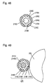
- Fig. 47 is a perspective outline view showing another method of manufacturing the rotary roller of the track ball device according to embodiment 9 of the invention.
- Fig. 48 is a sectional view of an annular contacting portion of the rotary roller manufactured by the method.
- a rotary roller 216 is manufactured as being separated into a rotary shaft 217 and an annular contacting portion 218.
- a metal shaft 217B integrally having a movable contact 217A is outsert-formed with insulating resin to form an insulating portion 217C, and the rotary shaft 217 is thus manufactured.
- the annular contacting portion 218 has a structure as shown in Fig. 48.
- An annular element 218B is made of rigid material such as metal and has plural protrusions 218A projecting radially at a specified angle interval on the outer circumference.
- each protrusion 218A of the annular element 218B made of rigid material is set so as to form a necessary angle interval for allowing the ball 205, i.e., the operating element to contact with the leading end.
- Fig. 49 is an enlarged sectional view of the contacting portion of the rotary roller and the ball.
- the annular contacting portion 218 of the rotary roller 216 thus formed has a recess 218E made of rigid material, and a bump 218C made of elastic material disposed alternately at a specified angle interval to form undulations on the outer circumference. Therefore, as shown in Fig. 49, the rotation of the ball 205 is transmitted securely to the rotary roller 216 without a slip by a large frictional force between the bump 218C made of elastic material of the rotary roller 216 and the ball 205. When the rotation of the ball 205 is not transmitted to the rotary roller 216, the ball 205 slips with a slight frictional force in the recess 218E made of rigid material. Therefore, the track ball device operating stably by smooth manipulation is obtained.
- the entire surface of the ball 205 may be coated with a film made of elastic material.
- the frictional force between the ball 205 and the contacting portions of the rollers 202, 203 can increase, and slip hardly in this contacting area, so that the track ball device operating stably is obtained.
- fine undulations smaller than the width of the recesses 206, 207 may be formed on the entire surface of the ball 205.
- the bump of the undulations on the surface of the ball 205 is hooked on the recesses 206, 207 on the outer circumference of the large-diameter portions 202A, 203A.
- the track ball device shown in embodiments 1 to 7 upon being used in the electronic apparatus having a display unit, provides a mechanism for generating a signal indicating that a position of a cursor on the display unit shown in embodiment 6.
- the invention relates to a track ball device for manipulating a cursor moving on a display screen of an electronic apparatus, and to an electronic apparatus using the device.
- a track ball device which generates a clear click feel when a ball is rotated, and which is capable of manipulating the move of the cursor on the display screen of the electronic apparatus precisely without generating a jerky feel in the manipulation is provided, and an electronic apparatus using the device is also provided.
Landscapes
- Engineering & Computer Science (AREA)
- General Engineering & Computer Science (AREA)
- Theoretical Computer Science (AREA)
- Human Computer Interaction (AREA)
- Physics & Mathematics (AREA)
- General Physics & Mathematics (AREA)
- Position Input By Displaying (AREA)
- Switches With Compound Operations (AREA)
- Mechanical Control Devices (AREA)
Abstract
Description
Similarly, by rotation of the
Claims (48)
- A track ball device comprising:a ball;four rollers having a circular shaft shape disposed in a square, two sets of two opposite rollers of said rollers being disposed in orthogonal to each other, said rollers being rotated with said ball while contacting with a outer circumference below a center of said ball;rotating direction regulating units for allowing said two opposite rollers of said rollers to rotate only in opposite directions, respectively;rotation amount detecting units for detecting a rotation amount of said rollers;support units for supporting said rollers; anda base unit having said support unit disposed thereon.
- The track ball device of claim 1, wherein said rotating direction regulating units includes:ratchet gears each having sawtooth serrations disposed at equiangular positions on an circular outer circumference thereof, said rachet gears being disposed at sides of contacting portions of said rollers, respectvely, the ball contacting with said rollers at said contacting portions; andarresting ratchets elastically contacting with said sawtooth serrations, said sawtooth serrations of said ratchet gears provided on said opposite rollers being inclined in mutually opposite directions.
- The track ball device of claim 2, wherein a number of said sawtooth serrations of said ratchet gears is synchronized with a number of outputs of said rotation amount detecting units in one rotation of said rollers.
- The track ball device of claim 1, wherein said rotating direction regulating units includes:pins projecting radially at an equiangular interval from each of said rollers radially about a center of a rotation of each of said rollers; andarresting ratchets repeating elastically displacing and restoring as being pushed with said pins when said rollers rotate in a specified direction, said arresting rachets preventing said roller for rotating in a reverse direction against the specific direction by contacting with said pins.
- The track ball device of claim 4, wherein a number of said pins projecting from each of said rollers is synchronized with a number of outputs of each of said rotation amount detecting unit in one rotation of each of said rollers.
- The track ball device of claim 4 or 5, wherein said rotation amount detecting units include switches driven through said arresting ratchets, respectively.
- The track ball device of any one of claims 1 to 6, wherein said rotation amount detecting units include:movable contact provided on outer circumferences of said rollers, respectively; androtary switches supported on said base unit, said rotary switches having elastic fixed contacts elastically contacting with said movable contacts, respectively.
- The track ball device of any one of claims 1 to 7, wherein said rollers contact with said ball on the same plane.
- The track ball device of any one of claims 1 to 8, wherein said support units include elastic members for pushing said rollers for narrowing an interval between said opposite rollers, and
wherein the interval is increased with an own weight of said ball and a pressure during a manipulation of said ball. - The track ball device of any one of claims 1 to 7, wherein a clearance is formed between said ball and rollers while said ball is not manipulated.
- The track ball device of claim 10, further comprising a self-resetting push switch contacting with a lower side of said ball.
- The track ball device of any one of claims 1 to 11, wherein said ball includes a film made of elastic material covering an entire surface thereof.
- The track ball device of any one of claims 1 to 11, wherein recesses are formed on an entire surface of said ball.
- The track ball device of any one of claims 1 to 13, further comprising:wherein said ball is surrounded by said case and lid plate.a case including:a bowl unit having an opening formed at an upper end thereof, said bowl unit having through-holes formed at positions where said rollers contact with said ball; anda peripheral wall extending from an outer circumference of an upper end of said bowl unit, said peripheral wall being fixed to said base unit; anda lid plate detachably disposed at said opening of said case, said lid plate having a ring-shape, said lid plate having a center circular hole smaller than a diameter of said ball,
- The track ball device of any one of claims 1 to 14, further comprising elastic output terminals of said rotation amount detecting units projecting extending from an opposite side to said support units about said base unit.
- An electronic apparatus comprising:said track ball device of claim 15; anda circuit board with which said elastic output terminals elastically contact.
- An electronic apparatus comprising:wherein the information can be selected with an output signal of at least one of said rotation amount detecting units by rotating said ball.said track ball device of any one of claims 1 to 15, anddisplay means for displaying information,
- The track ball device of claim 1,wherein each of said rollers includes sawtooth serrations having a specified number of undulations having a specified step, said circular sawtooth serrations being formed at an equal interval of a section at a portion where said ball contacts, directions of said sawtooth serrations of said two opposite rollers are opposite to each other, andwherein each of said rotating direction regulating units are formed at said portion where said ball contacts.
- The track ball device of claim 18, wherein a number of said sawtooth serrations formed on each of said rollers is synchronized with a number of an output of each of said rotation amount detecting units.
- The track ball device of claim 18 or 19,wherein said support unit includes an elastic member for pushing said rollers in a direction for narrowing an interval between said opposite rollers, andwherein the interval is increased by an own weight of said ball and a pressure during a manipulation of said ball.
- The track ball device of any one of claims 18 to 20, wherein a sectional shape of said sawtooth serrations is formed by overlaying a specified number of arcs by deviating a reference circle by the specified step in a radial direction of each of said rollers having said undulations, and said arcs are cut off in the radial direction.
- The track ball device of any one of claims 18 to 21, wherein said ball includes a film made of elastic material for covering an entire surface thereof.
- The track ball device of any one of claims 18 to 21, wherein recesses are formed on said entire surface of said ball.
- The track ball device of any one of claims 18 to 23, further comprising:wherein said ball is surrounded by said case and lid plate.a case including:a bowl unit having an opening at an upper end thereof, said bowl unit having through-holes formed at positions where said rollers contact with said ball; anda peripheral wall extending from an outer circumference of an upper end of said bowl unit, said peripheral wall being fixed to said base unit; anda lid plate detachably disposed at said opening of said case, said lid plate having a ring-shape, said lid plate having a center hole smaller than a diameter of said ball, being detachably disposed in the opening of the upper end of the case unit,
- The track ball device of any one of claims 18 to 24,wherein each of said rollers includes a cam, andwherein each of said rotation amount detecting units includes a switch driven by said cam.
- The track ball device of any one of claims 18 to 24,wherein each of said rollers includes a movable contact on an outer circumference thereof, andwherein each of said rotation amount detecting units includes an elastic fixed contact elastically contacting with said movable contact.
- The track ball device of any one of claims 18 to 26, further comprising elastic output terminals of said rotation amount detecting units projecting from an opposite side of said support units disposed on said base unit.
- The track ball device of any one of claims 18 to 26, further comprising:a circuit board for rotatably supporting said base unit; anda self-resetting push switch disposed on said circuit board said self-resetting push switch being pushed to operate when said base unit rotates.
- The track ball device of claim 28, wherein said rotation amount detecting units are disposed at said circuit board.
- The track ball device of claim 28, wherein said rotation amount detecting units are disposed at said base unit.
- The track ball device of claim 30, further comprising elastic output terminals of said rotation amount detecting units projecting from an opposite side to said support units disposed on said base unit, wherein said elastic output terminals are elastically coupled with said circuit board.
- The track ball device of claim 30, further comprising a flexible connection board for connecting said elastic output terminals to said circuit board.
- An electronic apparatus comprising:said track ball device of any one of claims 18 to 26;a circuit board rotatably supporting said base unit; anda self-resetting push switch disposed on said circuit board, said self-resetting push switch being pushed to operate when said base unit rotates.
- The electronic apparatus of claim 33, wherein said rotation amount detecting units are disposed at said circuit board.
- The electronic apparatus of claim 33, wherein said rotation amount detecting units are disposed at said base unit.
- The electronic apparatus of claim 35,wherein said track ball device further comprises an elastic output terminals of said rotation amount detecting units projecting from an opposite side to said support units disposed on said base unit, andwherein said elastic output terminals elastically contact to said circuit board.
- The electronic apparatus of claim 35, further comprising a flexible connection board for connecting said elastic output terminals of said rotation amount detecting units to said circuit board.
- An electronic apparatus comprising:wherein the information displayed by said display means is selected by an output signal of at least one of said rotation amount detecting units by rotating said ball.said track ball device of any one of claims 18 to 32;display means for displaying information; andan electronic circuit for controlling entirely said electronic apparatus,
- A track ball device comprising:a ball;X roller and Y roller of circular shaft shape having outer circumferences contacting with an outer circumference of said ball at contacting portions in directions orthogonal to each other, at least one of contacting portions having a plurality of recesses and bumps;two rotation amount detecting units coupled to said X roller and Y roller, respectively;a support unit contacting with said outer circumference of said ball at an intermediate position at a far side from said X roller and Y roller, said support unit supporting said ball rotatably in all directions; anda base unit for holding said X roller, Y roller and support unit.
- The track ball device of claim 39, wherein said support unit imcludes a third roller rotatably held therewith, said third roller contacting with said outer circumference of said ball.
- The track ball device of claim 39 or 40, wherein plural linear recesses are formed on at least one of said contacting portions said X roller and Y roller at a specified angle interval along a axial direction of said X roller and Y roller.
- The track ball device of claim 39 or 40, wherein at least one of said contacting portions of said X roller and Y roller includes:a substantially circular shaft made of rigid material; anda bump disposed on an outer circumference of said substantially circular shaft except a portion contacting with said ball, said bump having a long shape along an axis direction of said substantially circular shaft and a semicircular section, said bump being made of elastic material.
- The track ball device of any one of claims 39 to 42, wherein said ball includes a film made elastic material for covering an entire surface thereof.
- The track ball device of any one of claims 39 to 43, wherein small recesses having a smaller diameter than a width of said recesses are formed on said entire surface of said ball.
- The track ball device of any one of claims 39 to 44, wherein said rotation amount detecting units include:movable contacts disposed on outer circumferences coaxial with said X roller and Y roller, respectively; andelastic fixed contacts held at said base unit, said elastic fixed contacts elastically contacting with said movable contacts, respectively.
- The track ball device of any one of claims 39 to 45, further comprising:wherein said ball is surrounded by said case and ring unit.a case including:a bowl unit having an opening at an upper end thereof, said bowl unit having through-holes formed at positions where said X roller, Y roller, and support unit contact with said ball; anda peripheral wall extending from an outer circumference of said opening, said peripheral wall being fixed to said base unit; anda ring unit detachably disposed at said opening of said case unit, said ring having a center circular hole smaller than a diameter of said ball,
- The track ball device of any one of claims 39 to 46, wherein said rotation amount detecting units include elastic connection terminals, respectively.
- An electronic apparatus comprising:wherein the information displayed by said display means is selected by at least one output signal of said rotation amount detecting units by rotating said ball.said track ball device of any one of claims 39 to 47; anddisplay means for displaying information,
Applications Claiming Priority (7)
| Application Number | Priority Date | Filing Date | Title |
|---|---|---|---|
| JP2000028668A JP4000736B2 (en) | 2000-02-07 | 2000-02-07 | Trackball device and electronic apparatus using the same |
| JP2000028668 | 2000-02-07 | ||
| JP2000066502 | 2000-03-10 | ||
| JP2000066502A JP4000741B2 (en) | 2000-03-10 | 2000-03-10 | Trackball device and electronic apparatus using the same |
| JP2000076202A JP4000744B2 (en) | 2000-03-17 | 2000-03-17 | Trackball device and electronic component using the same |
| JP2000076202 | 2000-03-17 | ||
| PCT/JP2001/000821 WO2001059556A1 (en) | 2000-02-07 | 2001-02-06 | Track ball device and electronic apparatus comprising the same |
Publications (3)
| Publication Number | Publication Date |
|---|---|
| EP1176499A1 true EP1176499A1 (en) | 2002-01-30 |
| EP1176499A4 EP1176499A4 (en) | 2009-02-25 |
| EP1176499B1 EP1176499B1 (en) | 2012-04-11 |
Family
ID=27342267
Family Applications (1)
| Application Number | Title | Priority Date | Filing Date |
|---|---|---|---|
| EP01902779A Expired - Lifetime EP1176499B1 (en) | 2000-02-07 | 2001-02-06 | Track ball device and electronic apparatus comprising the same |
Country Status (5)
| Country | Link |
|---|---|
| US (2) | US6909422B2 (en) |
| EP (1) | EP1176499B1 (en) |
| KR (1) | KR100481944B1 (en) |
| CN (2) | CN1322404C (en) |
| WO (1) | WO2001059556A1 (en) |
Cited By (3)
| Publication number | Priority date | Publication date | Assignee | Title |
|---|---|---|---|---|
| WO2002071323A1 (en) * | 2001-03-07 | 2002-09-12 | Dimentor Aps | A 3d track ball system |
| EP2466425A4 (en) * | 2010-07-20 | 2012-11-28 | Huawei Device Co Ltd | Terminal trace ball navigation device and navigation method |
| US9768746B2 (en) | 2013-09-10 | 2017-09-19 | Bose Corporation | User interfaces and related devices and systems |
Families Citing this family (21)
| Publication number | Priority date | Publication date | Assignee | Title |
|---|---|---|---|---|
| US6480185B1 (en) * | 1999-07-28 | 2002-11-12 | Nokia Mobile Phones Limited | Electronic device with trackball user input |
| CN1322404C (en) * | 2000-02-07 | 2007-06-20 | 松下电器产业株式会社 | Track ball device and electronic apparatus using the same |
| CN1187680C (en) * | 2000-08-18 | 2005-02-02 | 株式会社海尼克斯 | Multiway ball type switch and its operation method |
| FR2822271B1 (en) * | 2001-03-16 | 2003-05-02 | Itt Mfg Enterprises Inc | BALL DEVICE FOR CONTROLLING THE MOVEMENTS OF A CURSOR ON AN ELECTRONIC DEVICE SCREEN |
| US7522155B2 (en) * | 2003-01-16 | 2009-04-21 | Panasonic Corporation | Trackball device and vehicle incorporating the same |
| US20040242288A1 (en) * | 2003-05-29 | 2004-12-02 | Henrik Balle | Portable communication apparatus, a rotary input device having an end-user-exchangeable element, and an end-user-exchangeable element for a rotary input device |
| JP4179085B2 (en) * | 2003-07-16 | 2008-11-12 | 松下電器産業株式会社 | Electronics |
| US7620915B2 (en) * | 2004-02-13 | 2009-11-17 | Ludwig Lester F | Electronic document editing employing multiple cursors |
| JP4311254B2 (en) * | 2004-03-31 | 2009-08-12 | 日本電気株式会社 | Portable electronic devices |
| JP2006260179A (en) * | 2005-03-17 | 2006-09-28 | Matsushita Electric Ind Co Ltd | Trackball equipment |
| KR100657788B1 (en) * | 2005-04-13 | 2006-12-14 | (주)리치콤전자 | Trackball switch and electronic device having the same |
| US20060284840A1 (en) * | 2005-06-15 | 2006-12-21 | Research In Motion Limited | Portable electronic device including pointer and related methods |
| EP1777608B1 (en) * | 2005-10-07 | 2010-01-20 | Research In Motion Limited | Portable electronic device including trackball unit and associated methods |
| US20070080946A1 (en) * | 2005-10-07 | 2007-04-12 | Research In Motion Limited | Portable electronic device including trackball unit and associated methods |
| CN100483318C (en) * | 2005-12-16 | 2009-04-29 | 鸿富锦精密工业(深圳)有限公司 | Cursor positioner and protable device therewith |
| US8896527B2 (en) * | 2009-04-07 | 2014-11-25 | Samsung Electronics Co., Ltd. | Multi-resolution pointing system |
| CN102562978A (en) * | 2010-12-17 | 2012-07-11 | 天津市海日电子有限公司 | Precise transmission device of control ball |
| US8730160B2 (en) * | 2011-02-07 | 2014-05-20 | Blackberry Limited | Retention mechanism for a navigation tool |
| KR101626862B1 (en) | 2015-07-28 | 2016-06-03 | 계룡환경주식회사 | A ball drive unit and a ball drive vehicle comprising the same |
| FR3052888B1 (en) * | 2016-06-21 | 2018-07-13 | Thales Sa | DEVICE FOR ADJUSTING THE BRAKING EFFORT OF A CONTROL BALL OR "TRACKBAL" AND CONTROL BALL THEREFOR |
| TWI817452B (en) * | 2022-01-03 | 2023-10-01 | 致伸科技股份有限公司 | Input device |
Family Cites Families (28)
| Publication number | Priority date | Publication date | Assignee | Title |
|---|---|---|---|---|
| US4505165A (en) * | 1982-06-01 | 1985-03-19 | Wico Corporation | Trackball device |
| JPS5994133A (en) | 1982-11-20 | 1984-05-30 | Fuji Xerox Co Ltd | Document and figure generating device |
| DE3662320D1 (en) * | 1986-10-25 | 1989-04-13 | Hewlett Packard Gmbh | Device to control the movement of a picture screen cursor |
| JPH0620187Y2 (en) * | 1989-05-26 | 1994-05-25 | アルプス電気株式会社 | Trackball |
| JPH0312858A (en) | 1989-06-12 | 1991-01-21 | Alpine Electron Inc | Recording medium reproducing system |
| JPH0629327B2 (en) | 1990-08-08 | 1994-04-20 | 近代化学工業株式会社 | Method for producing aqueous emulsion |
| JPH0493329U (en) * | 1990-12-28 | 1992-08-13 | ||
| DE4105352A1 (en) | 1991-02-21 | 1992-08-27 | Kugelfischer G Schaefer & Co | Electric machine with rotor and stator formed from compressed metallic powder - bonded by soft magnetic highly permeable metal particles covered by thin insulating layer |
| JPH0583837U (en) * | 1991-05-31 | 1993-11-12 | ミツミ電機株式会社 | Trackball |
| JPH0555227A (en) | 1991-08-27 | 1993-03-05 | Seiko Epson Corp | Semiconductor integrated circuit |
| JPH0583837A (en) | 1991-09-18 | 1993-04-02 | Hitachi Cable Ltd | Cable deformation prevention method |
| JP2584731Y2 (en) * | 1991-12-27 | 1998-11-05 | 株式会社ミヨシ | Track ball |
| JPH05233146A (en) * | 1992-02-25 | 1993-09-10 | Sony Corp | Three-dimensional input device |
| JPH0683530A (en) | 1992-09-04 | 1994-03-25 | Funai Electric Co Ltd | Switch mechanism for track ball device |
| JPH06102996A (en) | 1992-09-18 | 1994-04-15 | Fujitsu Ltd | mouse |
| US5428368A (en) * | 1992-09-30 | 1995-06-27 | Grant; Alan H. | Combination mouse and track ball unit |
| JPH0712858A (en) | 1993-06-24 | 1995-01-17 | Koichi Hase | Control current detecting circuit for electric and electronic circuit |
| JPH0798632A (en) * | 1993-09-29 | 1995-04-11 | Hosiden Corp | Track ball roller |
| JP3628358B2 (en) * | 1994-05-09 | 2005-03-09 | 株式会社ソニー・コンピュータエンタテインメント | Game console controller |
| JP3012858U (en) * | 1994-12-22 | 1995-06-27 | シスグレイション リミテッド | Coaxial cylindrical noiseless mechanical displacement code arranging device |
| JPH08185259A (en) * | 1994-12-28 | 1996-07-16 | Matsushita Electric Ind Co Ltd | Trackball equipment |
| US5583541A (en) * | 1995-02-03 | 1996-12-10 | Tandberg Data Storage As | Mouse and trackball design with contact-less roller sensor |
| JPH09282088A (en) | 1996-04-10 | 1997-10-31 | Sony Corp | Trackball |
| JPH09319483A (en) | 1996-05-27 | 1997-12-12 | Toshiba Corp | Document creation device |
| JPH10320115A (en) | 1997-05-22 | 1998-12-04 | Omron Corp | Track ball |
| JPH1139090A (en) * | 1997-07-23 | 1999-02-12 | Hitachi Commun Syst Inc | Presentation mouse |
| US6809722B2 (en) * | 1999-03-29 | 2004-10-26 | Yu Mei | Hand-held mobile mouse |
| CN1322404C (en) * | 2000-02-07 | 2007-06-20 | 松下电器产业株式会社 | Track ball device and electronic apparatus using the same |
-
2001
- 2001-02-06 CN CNB2005100640672A patent/CN1322404C/en not_active Expired - Fee Related
- 2001-02-06 CN CNB018001661A patent/CN1204488C/en not_active Expired - Fee Related
- 2001-02-06 US US09/958,132 patent/US6909422B2/en not_active Expired - Lifetime
- 2001-02-06 WO PCT/JP2001/000821 patent/WO2001059556A1/en not_active Ceased
- 2001-02-06 KR KR10-2001-7012755A patent/KR100481944B1/en not_active Expired - Fee Related
- 2001-02-06 EP EP01902779A patent/EP1176499B1/en not_active Expired - Lifetime
-
2005
- 2005-02-15 US US11/057,520 patent/US7158119B2/en not_active Expired - Fee Related
Cited By (3)
| Publication number | Priority date | Publication date | Assignee | Title |
|---|---|---|---|---|
| WO2002071323A1 (en) * | 2001-03-07 | 2002-09-12 | Dimentor Aps | A 3d track ball system |
| EP2466425A4 (en) * | 2010-07-20 | 2012-11-28 | Huawei Device Co Ltd | Terminal trace ball navigation device and navigation method |
| US9768746B2 (en) | 2013-09-10 | 2017-09-19 | Bose Corporation | User interfaces and related devices and systems |
Also Published As
| Publication number | Publication date |
|---|---|
| CN1322404C (en) | 2007-06-20 |
| US6909422B2 (en) | 2005-06-21 |
| EP1176499A4 (en) | 2009-02-25 |
| CN1363059A (en) | 2002-08-07 |
| CN1673948A (en) | 2005-09-28 |
| KR20010108461A (en) | 2001-12-07 |
| US20020190985A1 (en) | 2002-12-19 |
| US20050156893A1 (en) | 2005-07-21 |
| WO2001059556A1 (en) | 2001-08-16 |
| CN1204488C (en) | 2005-06-01 |
| KR100481944B1 (en) | 2005-04-13 |
| US7158119B2 (en) | 2007-01-02 |
| EP1176499B1 (en) | 2012-04-11 |
Similar Documents
| Publication | Publication Date | Title |
|---|---|---|
| EP1176499A1 (en) | Track ball device and electronic apparatus comprising the same | |
| US7042445B2 (en) | Input device for moving cursor and scrolling image on screen | |
| EP0640937B1 (en) | Input control device | |
| CN1162768C (en) | Mouse with turntable | |
| JP2004523834A (en) | Computer mouse | |
| EP1687703B1 (en) | A modular assembly for a self-indexing computer pointing device | |
| US5883617A (en) | Pointing device with improved cursor control data | |
| US20060139323A1 (en) | Puck-based pointing device that provides multiple buttons | |
| JP2942098B2 (en) | Multi-directional input device | |
| JP4000736B2 (en) | Trackball device and electronic apparatus using the same | |
| JP2001075724A (en) | Input device | |
| JP4000744B2 (en) | Trackball device and electronic component using the same | |
| CN1415086A (en) | Operating device for electronic functional equipment | |
| KR200155369Y1 (en) | Luminous Touch Pen | |
| KR100402333B1 (en) | remote control device of display and ball switch | |
| JP2004172042A (en) | Rotary switch | |
| CN223320800U (en) | A wireless knob controller | |
| EP1672472A1 (en) | Data input device, information equipment, information equipment control method, and computer program | |
| CN218826793U (en) | Hierarchical speed governing switch and broken wall machine | |
| KR100339897B1 (en) | multiplex operating switch | |
| JP3956576B2 (en) | Trackball device and electronic apparatus using the same | |
| JP2004246676A (en) | Input device and electronic device provided with same | |
| KR200189861Y1 (en) | Mouse for computer | |
| US20060045290A1 (en) | Mechanical roller controller | |
| JPH1195913A (en) | Pointing device |
Legal Events
| Date | Code | Title | Description |
|---|---|---|---|
| PUAI | Public reference made under article 153(3) epc to a published international application that has entered the european phase |
Free format text: ORIGINAL CODE: 0009012 |
|
| 17P | Request for examination filed |
Effective date: 20011005 |
|
| AK | Designated contracting states |
Kind code of ref document: A1 Designated state(s): AT BE CH CY DE DK ES FI FR GB GR IE IT LI LU MC NL PT SE TR |
|
| AX | Request for extension of the european patent |
Free format text: AL;LT;LV;MK;RO;SI |
|
| RBV | Designated contracting states (corrected) |
Designated state(s): DE FI FR GB SE |
|
| RAP1 | Party data changed (applicant data changed or rights of an application transferred) |
Owner name: PANASONIC CORPORATION |
|
| A4 | Supplementary search report drawn up and despatched |
Effective date: 20090126 |
|
| 17Q | First examination report despatched |
Effective date: 20090624 |
|
| GRAP | Despatch of communication of intention to grant a patent |
Free format text: ORIGINAL CODE: EPIDOSNIGR1 |
|
| GRAS | Grant fee paid |
Free format text: ORIGINAL CODE: EPIDOSNIGR3 |
|
| GRAA | (expected) grant |
Free format text: ORIGINAL CODE: 0009210 |
|
| AK | Designated contracting states |
Kind code of ref document: B1 Designated state(s): DE FI FR GB SE |
|
| REG | Reference to a national code |
Ref country code: GB Ref legal event code: FG4D |
|
| REG | Reference to a national code |
Ref country code: DE Ref legal event code: R096 Ref document number: 60146371 Country of ref document: DE Effective date: 20120606 |
|
| PG25 | Lapsed in a contracting state [announced via postgrant information from national office to epo] |
Ref country code: SE Free format text: LAPSE BECAUSE OF FAILURE TO SUBMIT A TRANSLATION OF THE DESCRIPTION OR TO PAY THE FEE WITHIN THE PRESCRIBED TIME-LIMIT Effective date: 20120411 Ref country code: FI Free format text: LAPSE BECAUSE OF FAILURE TO SUBMIT A TRANSLATION OF THE DESCRIPTION OR TO PAY THE FEE WITHIN THE PRESCRIBED TIME-LIMIT Effective date: 20120411 |
|
| PLBE | No opposition filed within time limit |
Free format text: ORIGINAL CODE: 0009261 |
|
| STAA | Information on the status of an ep patent application or granted ep patent |
Free format text: STATUS: NO OPPOSITION FILED WITHIN TIME LIMIT |
|
| 26N | No opposition filed |
Effective date: 20130114 |
|
| PGFP | Annual fee paid to national office [announced via postgrant information from national office to epo] |
Ref country code: DE Payment date: 20130219 Year of fee payment: 13 |
|
| REG | Reference to a national code |
Ref country code: DE Ref legal event code: R097 Ref document number: 60146371 Country of ref document: DE Effective date: 20130114 |
|
| GBPC | Gb: european patent ceased through non-payment of renewal fee |
Effective date: 20130206 |
|
| REG | Reference to a national code |
Ref country code: FR Ref legal event code: ST Effective date: 20131031 |
|
| PG25 | Lapsed in a contracting state [announced via postgrant information from national office to epo] |
Ref country code: GB Free format text: LAPSE BECAUSE OF NON-PAYMENT OF DUE FEES Effective date: 20130206 Ref country code: FR Free format text: LAPSE BECAUSE OF NON-PAYMENT OF DUE FEES Effective date: 20130228 |
|
| REG | Reference to a national code |
Ref country code: DE Ref legal event code: R119 Ref document number: 60146371 Country of ref document: DE |
|
| REG | Reference to a national code |
Ref country code: DE Ref legal event code: R119 Ref document number: 60146371 Country of ref document: DE Effective date: 20140902 |
|
| PG25 | Lapsed in a contracting state [announced via postgrant information from national office to epo] |
Ref country code: DE Free format text: LAPSE BECAUSE OF NON-PAYMENT OF DUE FEES Effective date: 20140902 |