EP1176484A2 - Communication method of an electronic apparatus - Google Patents
Communication method of an electronic apparatus Download PDFInfo
- Publication number
- EP1176484A2 EP1176484A2 EP01306273A EP01306273A EP1176484A2 EP 1176484 A2 EP1176484 A2 EP 1176484A2 EP 01306273 A EP01306273 A EP 01306273A EP 01306273 A EP01306273 A EP 01306273A EP 1176484 A2 EP1176484 A2 EP 1176484A2
- Authority
- EP
- European Patent Office
- Prior art keywords
- electronic apparatus
- control signal
- connection
- input
- computer
- Prior art date
- Legal status (The legal status is an assumption and is not a legal conclusion. Google has not performed a legal analysis and makes no representation as to the accuracy of the status listed.)
- Granted
Links
Images




Classifications
-
- G—PHYSICS
- G06—COMPUTING OR CALCULATING; COUNTING
- G06F—ELECTRIC DIGITAL DATA PROCESSING
- G06F12/00—Accessing, addressing or allocating within memory systems or architectures
- G06F12/02—Addressing or allocation; Relocation
- G06F12/06—Addressing a physical block of locations, e.g. base addressing, module addressing, memory dedication
- G06F12/0646—Configuration or reconfiguration
- G06F12/0653—Configuration or reconfiguration with centralised address assignment
- G06F12/0661—Configuration or reconfiguration with centralised address assignment and decentralised selection
-
- G—PHYSICS
- G05—CONTROLLING; REGULATING
- G05B—CONTROL OR REGULATING SYSTEMS IN GENERAL; FUNCTIONAL ELEMENTS OF SUCH SYSTEMS; MONITORING OR TESTING ARRANGEMENTS FOR SUCH SYSTEMS OR ELEMENTS
- G05B19/00—Program-control systems
- G05B19/02—Program-control systems electric
- G05B19/04—Program control other than numerical control, i.e. in sequence controllers or logic controllers
- G05B19/042—Program control other than numerical control, i.e. in sequence controllers or logic controllers using digital processors
- G05B19/0423—Input/output
-
- H—ELECTRICITY
- H04—ELECTRIC COMMUNICATION TECHNIQUE
- H04N—PICTORIAL COMMUNICATION, e.g. TELEVISION
- H04N23/00—Cameras or camera modules comprising electronic image sensors; Control thereof
- H04N23/60—Control of cameras or camera modules
- H04N23/66—Remote control of cameras or camera parts, e.g. by remote control devices
-
- H—ELECTRICITY
- H04—ELECTRIC COMMUNICATION TECHNIQUE
- H04N—PICTORIAL COMMUNICATION, e.g. TELEVISION
- H04N7/00—Television systems
- H04N7/18—Closed-circuit television [CCTV] systems, i.e. systems in which the video signal is not broadcast
- H04N7/181—Closed-circuit television [CCTV] systems, i.e. systems in which the video signal is not broadcast for receiving images from a plurality of remote sources
-
- G—PHYSICS
- G05—CONTROLLING; REGULATING
- G05B—CONTROL OR REGULATING SYSTEMS IN GENERAL; FUNCTIONAL ELEMENTS OF SUCH SYSTEMS; MONITORING OR TESTING ARRANGEMENTS FOR SUCH SYSTEMS OR ELEMENTS
- G05B2219/00—Program-control systems
- G05B2219/20—Pc systems
- G05B2219/21—Pc I-O input output
- G05B2219/21028—Address of module determined by position
-
- G—PHYSICS
- G05—CONTROLLING; REGULATING
- G05B—CONTROL OR REGULATING SYSTEMS IN GENERAL; FUNCTIONAL ELEMENTS OF SUCH SYSTEMS; MONITORING OR TESTING ARRANGEMENTS FOR SUCH SYSTEMS OR ELEMENTS
- G05B2219/00—Program-control systems
- G05B2219/20—Pc systems
- G05B2219/21—Pc I-O input output
- G05B2219/21033—Serial transfer address to each module, decrement, if zero module found
-
- G—PHYSICS
- G05—CONTROLLING; REGULATING
- G05B—CONTROL OR REGULATING SYSTEMS IN GENERAL; FUNCTIONAL ELEMENTS OF SUCH SYSTEMS; MONITORING OR TESTING ARRANGEMENTS FOR SUCH SYSTEMS OR ELEMENTS
- G05B2219/00—Program-control systems
- G05B2219/20—Pc systems
- G05B2219/21—Pc I-O input output
- G05B2219/21035—Identification with serial header
-
- G—PHYSICS
- G05—CONTROLLING; REGULATING
- G05B—CONTROL OR REGULATING SYSTEMS IN GENERAL; FUNCTIONAL ELEMENTS OF SUCH SYSTEMS; MONITORING OR TESTING ARRANGEMENTS FOR SUCH SYSTEMS OR ELEMENTS
- G05B2219/00—Program-control systems
- G05B2219/20—Pc systems
- G05B2219/21—Pc I-O input output
- G05B2219/21039—Followers, modules in daisy chain, each handles control data, transmits to next
Definitions
- the present invention relates to a communication method of an electronic apparatus in which communication is performed by integrally controlling a plurality of apparatuses, such as cameras or the like.
- PC personal computer
- RS-232C standards
- this conventional method of performing communication by serially connecting electronic apparatuses it is necessary to provide at each of the electronic apparatuses a terminal for determining whether or not other electronic apparatuses are connected at the following stage, in addition to signal lines for transmitting/receiving control signals for the electronic apparatus.
- the present invention is an electronic apparatus, among a plurality of electronic apparatuses serially connected to a computer, which can communicate a control command signal and first and second control signals.
- the electronic apparatus includes first communication means for communicating the control command signal and the first and second control signals with an electronic apparatus provided at an immediately preceding stage of connection, second communication means for communicating the control command signal and the first and second control signals with an electronic apparatus provided at an immediately succeeding stage of connection.
- Processing means provides the first control signal, outputting the provided first control signal to an electronic apparatus to be connected at an immediately succeeding stage of connection via the second communication means, determines whether or not the second control signal has been input in response to the output of the first control signal, and notifies, when it has been determined that the second control signal has not been input, the computer of the fact that the concerned electronic apparatus is connected at a last stage of connection via the first communication means.
- the present invention is a communication method of an electronic apparatus, from among a plurality of electronic apparatuses serially connected to a computer, which can communicate a control command signal and first and second control signals.
- the method includes the steps of newly providing the first control signal in accordance with input of the first control signal output from the computer or an electronic apparatus provided at an immediately preceding stage of connection, outputting the provided first control signal to an electronic apparatus to be connected at an immediately succeeding stage of connection, determining whether or not the second control signal has been input in response to the first control signal output to the electronic apparatus to be connected to the immediately succeeding stage of connection, and notifying, when the second control signal has not been input, the computer of the fact that the concerned electronic apparatus is at a last stage of connection.
- the present invention which is a storage medium storing communication modules of an electronic apparatus, from among a plurality of electronic apparatuses serially connected to a computer, which can communicate a control command signal and first and second control signals.
- the modules include a module of newly providing the first control signal in accordance with input of the first control signal output from the computer or an electronic apparatus provided at an immediately preceding stage of connection, a module of outputting the provided first control signal to an electronic apparatus to be connected at an immediately succeeding stage of connection, a module of determining whether or not the second control signal has been input in response to the first control signal output to the electronic apparatus to be connected at the immediately succeeding stage of connection, and a module of notifying, when the second control signal has not been input, the computer of the fact that the electronic apparatus is at a last stage of connection.
- FIG. 1 is a diagram illustrating the configuration of connection of electronic apparatuses according to an embodiment of the present invention
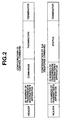
- FIG. 2 illustrates examples of commands to be transmitted and received between the electronic apparatuses in the embodiment
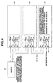
- FIGS. 3 and 4 are diagrams, each illustrating a control method in the configuration of connection of the electronic apparatuses in the embodiment
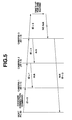
- FIG. 5 is a diagram illustrating an example of transmission and reception of a cascade connection command in the configuration of connection of the electronic apparatuses in the embodiment
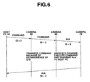
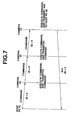
- FIGS. 6 and 7 are diagrams, each illustrating an example of transmission and reception of a control command in the configuration of connection of the electronic apparatuses in the embodiment
- FIG. 8 is a flowchart illustrating an operation process in an electronic apparatus in the embodiment.
- FIG. 9 is a flowchart illustrating an operation process in a host PC in the embodiment.
- FIG. 1 is a diagram illustrating a system for controlling serially connected electronic apparatuses via RS-232C ports from a host PC 40.
- a case of using cameras, whose pan and tilt can be controlled, as the electronic apparatuses will be described.
- pan and tilt of each of cameras 50, 60 and 70 can be controlled.
- the host PC 40 comprises, for example, a personal computer, and outputs a control command and a cascade connection command (to be described below) to the directly connected camera 50.
- a cable 10 is for exchanging commands between the host PC 40 and the camera 50.
- a cable 20 is for exchanging commands between the camera 50 and the camera 60.
- a cable 30 is for exchanging commands between the camera 60 and the camera 70.
- Each of the cameras 50, 60 and 70 has a first input/output terminal 3 and a second input/output terminal 5, each for inputting and outputting a control command and a cascade control command.
- the first input/output terminal 3 has an output port 3a and an input port 3b.
- the second input/output port 5 has an output port 5a and an input port 5b.
- Each of the cameras 50, 60 and 70 also has a CPU (central processing unit) 9 including a buffer memory (not shown).
- the CPU 9 has ports (terminals) 9a - 9d for exchanging commands with the first input/output terminal 3 and the second input/output terminal 5.
- Each of the cameras 50, 60 and 70 futher has a switch 11 for performing switching based on a signal from the port 9c.
- the host PC 40 has an input/output terminal 4 for inputting and outputting a control command and a cascade connection command.
- the input/output terminal 4 has an output port 4a and an input port 4b.
- FIG. 8 is a flowchart illustrating an operation process of the CPU 9 when a cascade connection command for recognizing a connection state of each of the cameras serially connected via the RS-232C ports by the host PC 40 has been input in the concerned camera (any of the cameras 50, 60 and 70).
- the cascade connection command is for causing the connected camera to set an ID and to recognize the set camera ID by the host PC 40.
- step S101 it is determined whether or not a cascade connection command has been received via the ports 3b and 9b. If the result of the determination in step S101 is affirmative, the process proceeds to step S102.
- step S102 the received cascade connection command is confirmed, and "the ID number of the transmitter's apparatus (a camera or the host PC 40) + 1" is set as the ID number of the concerned camera, and is stored in the buffer memory.
- step S103 it is determined whether or not the switch 11 is switched so that the ports 3a and 9a are connected. If the result of the determination in step S103 is affirmative, the process proceeds to step S105. If the result of the determination in step S103 is negative, the process proceeds to step S104, where the switch 11 is switched to connect the ports 3a and 9a by outputting a control signal from the port 9c.
- step S105 an Ack command is output from the port 3a to the apparatus of the transmitter of the cascade connection command via the port 9a.
- the Ack command is configured in the form of a packet including a header, the ID number of the transmitter's apparatus, the ID number of the transmission destination's apparatus, status information, serving as information relating to the transmitter's apparatus, and a terminator.
- step S106 After outputting the Ack command, then, in step S106, by outputting a control signal from the port 9c, switch 11 is switched to connect the ports 3a and 5b. Then, in step S107, a cascade connection command consisting of transmitter's apparatus ID number "xx" cascade “ON” is output from the output port 5a via the port 9a. Then, the process proceeds to step S108, where the switch 11 is switched by outputting a control signal from the port 9c after outputting the cascade connection command, to connect the output port 3a and the port 9a.
- step S109 it is determined whether or not an Ack command including the transmitter's apparatus ID number equal to the concerned camera's ID number + 1 has been input from the port 9d via the port 5b. If the result of the determination in step S109 is affirmative, the process proceeds to step S110, where the switch 11 is switched by outputting a control signal from the port 9c to connect the output port 3a and the input port 5b, and the process is then terminated. If the result of the determination in step S109 is negative, the process proceeds to step S111, where it is determined whether or not a predetermined time period has elapsed. If the result of the determination in step S111 is negative, the process returns to step S109, where input of an Ack command is awaited.
- step S112 information indicating that the concerned camera is at the last stage of connection is added to status information, and an Ack signal is output to the host PC 40.
- FIG. 9 is a flowchart illustrating the operation process of the host PC 40 when outputting a cascade connection command for recognizing the state of connection of a camera by the host PC 40.
- step S201 a cascade connection command consisting of transmitter's apparatus ID number "00" cascade "ON" is output. Then, the process proceeds to step S202, where it is determined whether or not an Ack signal from the camera at the last stage of connection has been received. If the result of the determination in step S202 is affirmative, the ID number and status information of the concerned camera are acquired, and the process is then terminated. If the result of the determination in step S202 is negative, the process proceeds to step S203, where it is determined whether or not a predetermined time period has elapsed after outputting the cascade connection command. If the result of the determination in step S203 is negative, the process returns to step S202. If the result of the determination in step S203 is affirmative, the host PC 40 outputs an error message, and the process is then terminated.
- the host PC 40 can know the state of connection of the camera. Furthermore, since it is possible to appropriately switch connection of internal terminals of each camera in advance, the number of signal lines connecting the cameras can be minimized.
- an initialization process is performed when the power supply of each of the cameras 50, 60 and 70 is turned on, whereby the ID number of each of the cameras 50, 60 and 70 is cleared, and the switch 11 is switched so as to connect the output port 3a and the port 9a in advance. Then, a cascade connection command consisting of the transmitter's apparatus ID number "00" cascade “ON” is output from the output port 4a of the host PC 40 to the directly connected camera 50.
- the output ports 3a and 5a are connected by switching the switch 11.
- a cascade connection command consisting of the transmitter's ID number "01" cascade “ON” is output from the output port 5a to the camera 60 via the port 9a. Then, by outputting a control signal from the output port 9c to the camera 60, the output port 3a and the port 9a are connected by switching the switch 11. When an Ack command is thereafter input from the camera 60, the operation process in the camera 50 is terminated.
- the output ports 3a and 5a are connected by switching the switch 11.
- a cascade connection command consisting of the transmitter's ID number "02" cascade “ON” is output from the output port 5a to the camera 70 via the port 9a.
- the output port 3a and the port 9a are connected by switching the switch 11.
- the output ports 3a and 5a are connected by switching the switch 11. Then, a cascade connection command consisting of the transmitter's ID number "03" cascade “ON” is output from the output port 5a via the port 9a. As shown in FIG. 4, since the camera 70 is at the last stage of connection, an Ack command is, of course, not input.
- the camera 70 After the lapse of a predetermined time period (for example, 1 second), the camera 70 confirms that an Ack command has not been input, and outputs an Ack signal to the host PC 40 by adding information that the camera 70 is at the last stage of connection to status information.
- the host PC 40 receives an Ack signal consisting of ID "03" output from the camera 70 within a maximum of 5 seconds after transmitting a cascade connection command, and therefore knows that three cameras are connected.
- the host PC 40 can execute control of the connected cameras according to processing to be described below.
- a cascade connection command is output when starting the connection system, a cascade connection command may be periodically output from the host PC 40. According to such processing, the current connection state can be exactly known even if the state of connection of the cameras has changed.
- FIG. 6 illustrates the operation process when the host PC 40 has transmitted a control command to the camera 60.
- the switch 11 of each camera has already been switched as shown in FIG. 4 so as to be able to deal with a case in which a control command is input. That is, the switch 11 is switched so as to connect the output port 3a and the port 9a of only the camera 70 at the last stage of connection, and the switch is switched so as to connect the output port 3a and the input port 5b in the cameras 50 and 60 to each of which apparatuses are preset at the immediately preceding stage and at the immediately succeeding stage of connection.
- a control command is output from the host PC 40 to the camera 50.
- the control command has the configuration of a packet including a header, the ID number of the transmission destination's apparatus (in the case of FIG. 6, "02" since the control command is for the camera 60), commands (such as pan and tilt commands), parameters (the amounts of driving for the commands), and a terminator.
- the CPU 9 of the camera 50 confirms the ID number of the destination of transmission of the input control command. Since the ID number of the camera 50 is "01", it is determined that the control command is not for the camera 50, and the control command is transferred to the camera 60.
- the CPU 9 of the camera 60 confirms the ID number of the destination of transmission of the input control command. Since the ID number of the camera 60 is "02", it is determined that the control command is for the camera 60, and the camera 60 is controlled based on the control command. Upon completion of the camera control, an Ack command in which the ID number of the transmission destination (the ID number "00" of the host PC 40) and the ID number of the transmitter (the ID number "02" of the camera 60) are added is output from the output port 5a via the port 9a.
- the CPU 9 of the camera 70 confirms the ID number of the destination of transmission of the input Ack command. Since the ID number of the camera 50 is "01", it is determined that the control command is not for the camera 50, and the Ack command is transferred to the camera 60.
- the host PC 40 receives the Ack command from the input port 4b, confirms that the control has been performed, and terminates the operation.
- command processing when a control command for the camera 60 is output from the host PC 40 has been described.
- the same processing may be executed by writing the ID number of the camera 50 or 70 in the ID number of the transmission destination in a control command and an Ack command.
- each of the cameras 50, 60 and 70 recognizes the ID number "00", and executes control based on the control command.
- an Ack command is output from the camera 70 to the host PC 40, and the process is terminated.
- control based on the control command is executed in all connected electronic apparatuses.
- the input/output terminals 3 and 5 and the CPU 9 are provided in each of the cameras 50, 60 and 70, the input/output terminals 3 and 5 and the CPU 9 may constitute a connection apparatus separate from the cameras 50, 60 and 70.
- the objects of the present invention may be achieved by supplying a system or an apparatus with a program of software for realizing the functions of the above-described embodiment, and reading and executing program codes stored in a storage medium by means of a computer (or a CPU or an MPU (microprocessor unit)) of the system or the apparatus via a network, such as the Internet or the like.
- a computer or a CPU or an MPU (microprocessor unit)
- the program codes themselves read from the storage medium realize the functions of the above-described embodiment, so that the storage medium storing the program codes constitutes the present invention.
- a floppy disk a hard disk, an optical disk, a magnetooptical disk, a CD(compact disc)-ROM (read-only memory), a CD-R (recordable), a magnetic tape, a nonvolatile memory card, a ROM or the like may be used as the storage medium for supplying the program codes.
- the present invention may also be applied not only to a case in which the functions of the above-described embodiment are realized by executing program codes read by a computer, but also to a case in which an OS (operating system) or the like operating in a computer executes a part or the entirety of actual processing, and the functions of the above-described embodiment are realized by the processing.
- an OS operating system
- the present invention may also be applied to a case in which, after writing program codes read from a storage medium into a memory provided in a function expanding board inserted into a computer or in a function expanding unit connected to the computer, a CPU or the like provided in the function expanding board or the function expanding unit performs a part or the entirety of actual processing based on instructions of the program codes, and the functions of the above-described embodiment are realized by the processing.
Landscapes
- Engineering & Computer Science (AREA)
- Multimedia (AREA)
- Signal Processing (AREA)
- Physics & Mathematics (AREA)
- General Physics & Mathematics (AREA)
- Theoretical Computer Science (AREA)
- Automation & Control Theory (AREA)
- General Engineering & Computer Science (AREA)
- Selective Calling Equipment (AREA)
- Studio Devices (AREA)
- Small-Scale Networks (AREA)
Abstract
Description
Claims (17)
- An electronic apparatus which can be associated with a plurality of other electronic apparatuses serially connected to a computer, which can communicate a control command signal and first and second control signals, said electronic apparatus comprising:first communication means for communicating the control command signal and the first and second control signals with an electronic apparatus of the plurality of electronic apparatuses provided at a preceding stage of connection;second communication means for communicating the control command signal and the first and second control signals with an electronic apparatus of the plurality of electronic apparatuses provided at a succeeding stage of connection; andprocessing means for providing the first control signal, outputting the provided first control signal to an electronic apparatus to be connected at an immediately succeeding stage of connection via said second communication means, determining whether or not the second control signal has been input in response to the output of the first control signal, and notifying, when it has been determined that the second control signal has not been input, the computer that said electronic apparatus is connected at a last stage of connection via said first communication means.
- An electronic apparatus according to Claim 1, wherein said processing means newly provides the first control signal in accordance with input of the first control signal from the electronic apparatus provided at the immediately preceding stage of connection via said first communication means.
- An electronic apparatus according to Claim 1, wherein, when said electronic apparatus has started, provision of the first control signal is started from the computer.
- An electronic apparatus according to Claim 1, wherein provision of the first control signal is started from the computer at a predetermined period.
- An electronic apparatus according to Claim 2, wherein said processing means sets an ID number of said electronic apparatus based on an ID number of the first control signal input from the electronic apparatus provided at the immediately preceding stage of connection.
- An electronic apparatus according to Claim 5, wherein said processing means sets a number obtained by adding one to the ID number of the first control signal input from the electronic apparatus provided at the immediately preceding stage of connection as an ID number of said electronic apparatus.
- An electronic apparatus according to Claim 5, wherein, when the control command has been input from said first communication means, said processing means determines whether or not control based on the control command is to be executed by discriminating an ID address of a destination of transmission of the control command.
- An electronic apparatus according to Claim 7, wherein, when the ID address of the destination of transmission of the control command coincides with the ID address of said electronic apparatus, said processing means executes the control based on the control command.
- An electronic apparatus according to Claim 7, wherein, when the ID address of the destination of transmission of the control command is a predetermined ID address, said processing means executes control based on the control command.
- An electronic apparatus according to Claim 1, wherein, when notifying the computer that said electronic apparatus is connected at a last stage of connection, via said first communication means, said processing means performs notification by adding a preset ID number of said electronic apparatus.
- A communication method of an electronic apparatus, from among a plurality of electronic apparatuses serially connected to a computer, which can communicate a control command signal and first and second control signals, said method comprising the steps of:newly providing the first control signal in accordance with input of the first control signal output from the computer or an electronic apparatus of the plurality of electronic apparatuses provided at a preceding stage of connection;outputting the provided first control signal to an electronic apparatus of the plurality of electronic apparatuses to be connected at a succeeding stage of connection;determining whether or not the second control signal has been input in response to the first control signal output to the electronic apparatus to be connected to the immediately succeeding stage of connection; andnotifying, when the second control signal has not been input, the computer that a concerned electronic apparatus is at a last stage of connection.
- A communication method according to Claim 11, further comprising the step of setting an ID address of the concerned electronic apparatus based on an ID address of the first control signal output from the computer or the electronic apparatus provided at the immediately preceding stage of connection.
- A communication method according to Claim 11, wherein in said determining step, when the second control signal has not been input, the computer is caused to recognize that the concerned electronic apparatus is at the last stage of connection by notifying the computer of the ID address of the concerned electronic apparatus.
- A storage medium storing communication modules of an electronic apparatus, from among a plurality of electronic apparatuses serially connected to a computer, which can communicate a control command signal and first and second control signals, said modules comprising:a module of newly providing the first control signal in accordance with input of the first control signal output from the computer or an electronic apparatus of the plurality of electronic apparatuses provided at a preceding stage of connection;a module of outputting the provided first control signal to an electronic apparatus of the plurality of electronic apparatuses to be connected at a succeeding stage of connection;a module of determining whether or not the second control signal has been input in response to the first control signal output to the electronic apparatus to be connected at the immediately succeeding stage of connection; anda module of notifying, when the second control signal has not been input, the computer that a concerned electronic apparatus is at a last stage of connection.
- A storage medium according to Claim 14, said modules further comprising a module of setting an ID address of the concerned electronic apparatus based on an ID address of the first control signal output from the computer or the electronic apparatus provided at the immediately preceding stage of connection.
- A storage medium according to Claim 14, wherein in said determining step, when the second control signal has not been input, the computer is caused to recognize that the concerned electronic apparatus is at the last stage of connection by notifying the computer of an ID address of the concerned electronic apparatus.
- A system comprising an apparatus as claimed in any one of claims 1 to 10 and connected to a computer which is in turn connected to other apparatuses.
Applications Claiming Priority (2)
| Application Number | Priority Date | Filing Date | Title |
|---|---|---|---|
| JP2000222193 | 2000-07-24 | ||
| JP2000222193A JP4467727B2 (en) | 2000-07-24 | 2000-07-24 | Electronic device connection method, electronic device, and storage medium storing operation processing program thereof |
Publications (3)
| Publication Number | Publication Date |
|---|---|
| EP1176484A2 true EP1176484A2 (en) | 2002-01-30 |
| EP1176484A3 EP1176484A3 (en) | 2003-11-12 |
| EP1176484B1 EP1176484B1 (en) | 2006-04-12 |
Family
ID=18716466
Family Applications (1)
| Application Number | Title | Priority Date | Filing Date |
|---|---|---|---|
| EP01306273A Expired - Lifetime EP1176484B1 (en) | 2000-07-24 | 2001-07-20 | Communication method of an electronic apparatus |
Country Status (4)
| Country | Link |
|---|---|
| US (1) | US6834321B2 (en) |
| EP (1) | EP1176484B1 (en) |
| JP (1) | JP4467727B2 (en) |
| DE (1) | DE60118668T2 (en) |
Cited By (5)
| Publication number | Priority date | Publication date | Assignee | Title |
|---|---|---|---|---|
| EP1667374A2 (en) | 2004-12-03 | 2006-06-07 | Sony Corporation | Apparatus connection interface, apparatus control system and method of controlling apparatus control system |
| EP1857942A1 (en) * | 2006-05-17 | 2007-11-21 | Valeo Systèmes Thermiques | Automatic actuator-addressing system in an automatic vehicle |
| US7330766B2 (en) | 2002-10-25 | 2008-02-12 | Citizen Holdings Co., Ltd. | Electronic device system |
| EP2066151A3 (en) * | 2007-11-14 | 2010-10-27 | ARC Solid-State Lighting Corporation | Lighting driving device and lighting system thereof |
| CN103403629A (en) * | 2011-03-15 | 2013-11-20 | 欧姆龙株式会社 | Control system, operation terminal, and program |
Families Citing this family (19)
| Publication number | Priority date | Publication date | Assignee | Title |
|---|---|---|---|---|
| US7203728B2 (en) * | 1993-01-26 | 2007-04-10 | Logic Controls, Inc. | Point-of-sale system and distributed computer network for same |
| US6928501B2 (en) * | 2001-10-15 | 2005-08-09 | Silicon Laboratories, Inc. | Serial device daisy chaining method and apparatus |
| US20050050063A1 (en) * | 2003-08-26 | 2005-03-03 | Haas William Robert | Data management system and method with multi-port processor |
| US7984195B2 (en) * | 2006-07-07 | 2011-07-19 | Logic Controls, Inc. | Hybrid industrial networked computer system |
| JP2006133996A (en) * | 2004-11-04 | 2006-05-25 | Canon Inc | Serial communication system and method |
| KR100643380B1 (en) * | 2004-11-17 | 2006-11-10 | 삼성전자주식회사 | Communication |
| JP2006201964A (en) * | 2005-01-19 | 2006-08-03 | Fuji Xerox Co Ltd | Computer system and image formation apparatus |
| TW201012130A (en) * | 2008-09-08 | 2010-03-16 | Brainchild Electronic Co Ltd | Remote communication method of a network and system thereof |
| US8296488B2 (en) | 2009-04-27 | 2012-10-23 | Abl Ip Holding Llc | Automatic self-addressing method for wired network nodes |
| US8705967B2 (en) * | 2011-07-28 | 2014-04-22 | Motorola Solutions, Inc. | Serially-distributed access points in a communication network |
| US9946679B2 (en) | 2011-10-05 | 2018-04-17 | Analog Devices, Inc. | Distributed audio coordination over a two-wire communication bus |
| US10649948B2 (en) * | 2011-10-05 | 2020-05-12 | Analog Devices, Inc. | Two-wire communication systems and applications |
| JP5930767B2 (en) | 2012-02-23 | 2016-06-08 | キヤノン株式会社 | Electronic device, communication control method |
| JP5968119B2 (en) * | 2012-06-27 | 2016-08-10 | キヤノン株式会社 | Communication system with cascade connection |
| JP5661702B2 (en) | 2012-08-23 | 2015-01-28 | キヤノン株式会社 | Electronic system and communication control method |
| KR101552255B1 (en) * | 2014-03-20 | 2015-09-09 | 김관석 | Block toy |
| JP2016096493A (en) * | 2014-11-17 | 2016-05-26 | 富士ゼロックス株式会社 | Communication system and image forming device |
| CN114554037B (en) * | 2020-11-26 | 2023-04-18 | 华为技术有限公司 | Data transmission method and electronic equipment |
| JP2024115692A (en) * | 2023-02-15 | 2024-08-27 | Koa株式会社 | Multiple Devices |
Family Cites Families (12)
| Publication number | Priority date | Publication date | Assignee | Title |
|---|---|---|---|---|
| US4443866A (en) * | 1975-08-27 | 1984-04-17 | Corning Glass Works | Automatic device selection circuit |
| FR2691558B1 (en) * | 1992-05-21 | 1997-08-01 | Sextant Avionique | DEVICE FOR MANAGING THE PRIORITY OF ACCESS TO COMMON RESOURCES, OF FUNCTIONAL MODULES DISTRIBUTED IN A PLURALITY OF LOCAL UNITS BY FORMING IN EACH OF THESE, A LOCAL "DAISY CHAIN". |
| US6272529B1 (en) * | 1993-01-26 | 2001-08-07 | Logic Controls, Inc. | Point-of-sale system and distributed computer network for same |
| JP3224326B2 (en) * | 1994-06-24 | 2001-10-29 | 富士通株式会社 | Disk device and disk subsystem |
| JPH08106413A (en) * | 1994-10-06 | 1996-04-23 | Fujitsu Ltd | Data processing device, data transfer method and memory device |
| DE19513747B4 (en) | 1995-04-11 | 2004-12-09 | Trieschmann, Olaf, Dr. | Method and device for controlling systems using a control computer |
| JPH09179810A (en) * | 1995-12-25 | 1997-07-11 | Matsushita Electric Works Ltd | Unit selecting device |
| DE19624528B4 (en) * | 1996-06-20 | 2009-05-20 | Robert Bosch Gmbh | Method for controlling information transmission between components and component for carrying out the method |
| EP0854609A3 (en) * | 1997-01-21 | 1999-12-22 | Nittan Company, Limited | Transmitting system |
| US5933656A (en) * | 1997-06-18 | 1999-08-03 | Raytheon Company | System for interfacing host computer to multiple peripheral devices using daisy-chainable bus and federated computational input/output circuit card assemblies |
| DE19740306A1 (en) | 1997-09-13 | 1999-03-18 | Dornier Gmbh Lindauer | Loom control |
| JP2000067352A (en) | 1998-06-16 | 2000-03-03 | Pittway Corp | Method and device for address allocation |
-
2000
- 2000-07-24 JP JP2000222193A patent/JP4467727B2/en not_active Expired - Fee Related
-
2001
- 2001-07-19 US US09/907,673 patent/US6834321B2/en not_active Expired - Fee Related
- 2001-07-20 EP EP01306273A patent/EP1176484B1/en not_active Expired - Lifetime
- 2001-07-20 DE DE60118668T patent/DE60118668T2/en not_active Expired - Lifetime
Cited By (10)
| Publication number | Priority date | Publication date | Assignee | Title |
|---|---|---|---|---|
| US7330766B2 (en) | 2002-10-25 | 2008-02-12 | Citizen Holdings Co., Ltd. | Electronic device system |
| EP1553726A4 (en) * | 2002-10-25 | 2009-06-10 | Citizen Holdings Co Ltd | Electronic device system |
| EP1667374A2 (en) | 2004-12-03 | 2006-06-07 | Sony Corporation | Apparatus connection interface, apparatus control system and method of controlling apparatus control system |
| EP1667374A3 (en) * | 2004-12-03 | 2009-11-18 | Sony Corporation | Apparatus connection interface, apparatus control system and method of controlling apparatus control system |
| US7840715B2 (en) | 2004-12-03 | 2010-11-23 | Sony Corporation | Apparatus connection interface, apparatus control system and method of controlling apparatus control system |
| EP1857942A1 (en) * | 2006-05-17 | 2007-11-21 | Valeo Systèmes Thermiques | Automatic actuator-addressing system in an automatic vehicle |
| FR2901211A1 (en) * | 2006-05-17 | 2007-11-23 | Valeo Systemes Thermiques | AUTOMATIC ADDRESSING SYSTEM FOR ACTUATORS IN A MOTOR VEHICLE. |
| EP2066151A3 (en) * | 2007-11-14 | 2010-10-27 | ARC Solid-State Lighting Corporation | Lighting driving device and lighting system thereof |
| CN103403629A (en) * | 2011-03-15 | 2013-11-20 | 欧姆龙株式会社 | Control system, operation terminal, and program |
| EP2672347A4 (en) * | 2011-03-15 | 2014-08-20 | Omron Tateisi Electronics Co | CONTROL SYSTEM, OPERATION TERMINAL AND PROGRAM |
Also Published As
| Publication number | Publication date |
|---|---|
| JP4467727B2 (en) | 2010-05-26 |
| DE60118668D1 (en) | 2006-05-24 |
| US20020016875A1 (en) | 2002-02-07 |
| JP2002044089A (en) | 2002-02-08 |
| EP1176484B1 (en) | 2006-04-12 |
| EP1176484A3 (en) | 2003-11-12 |
| DE60118668T2 (en) | 2006-10-05 |
| US6834321B2 (en) | 2004-12-21 |
Similar Documents
| Publication | Publication Date | Title |
|---|---|---|
| EP1176484A2 (en) | Communication method of an electronic apparatus | |
| US6859669B2 (en) | Apparatus and method of controlling activation of home automation system | |
| US5608490A (en) | Apparatus for and a method of communicating between a camera and external equipment | |
| CN113765608B (en) | Fault diagnosis method, electronic device, and storage medium | |
| US10651692B2 (en) | Power transmission device, power reception device, power supply system, and power transmission method | |
| US7492121B2 (en) | Smart battery and method for recognizing battery type using the same | |
| CN115101071A (en) | Low-power-consumption Bluetooth voice control terminal, method, device and equipment | |
| US7996697B2 (en) | Matching system of electronic device and peripheral device and matching method thereof | |
| US7660603B2 (en) | Card type electronic device system and card type electronic device | |
| EP1739569B1 (en) | Device and method for performing multi-function using unique port in wireless terminal | |
| JP2004064616A (en) | Baud rate setting method, baud rate setting program, readable recording medium, communication system and communication method | |
| KR102177230B1 (en) | Apparatus and method for serial communication control discriminating | |
| US20030172171A1 (en) | Communication control unit and information terminal unit equipped with the same | |
| CN116244254A (en) | RSMC chip, chip channel self-adaptive loading method and Beidou communication navigation device | |
| JP7596131B2 (en) | Relay device, control method and program | |
| US6889273B2 (en) | Communication adapter and network system using the communication adapter | |
| US20020013148A1 (en) | Telephone set identifying method, telephone set type identifying apparatus, processing apparatus and storage medium | |
| WO2005066745A1 (en) | Bus share adapter | |
| CN117640016B (en) | Baud rate negotiation method, device, computer equipment, chip and storage medium | |
| JP5059086B2 (en) | Electronic device and method of connecting electronic device | |
| US20050097237A1 (en) | Line-conducted interface arrangement and a method for operating a line-conducted interface arrangement between a host and a device | |
| EP1179907A2 (en) | Data communication apparatus and method with error correction mode | |
| EP4068107B1 (en) | Audio control circuit, host device and associated control method | |
| JPH10173688A (en) | Data communication device and method | |
| JP2001034720A (en) | Reader / writer for ID tag |
Legal Events
| Date | Code | Title | Description |
|---|---|---|---|
| PUAI | Public reference made under article 153(3) epc to a published international application that has entered the european phase |
Free format text: ORIGINAL CODE: 0009012 |
|
| AK | Designated contracting states |
Kind code of ref document: A2 Designated state(s): AT BE CH CY DE DK ES FI FR GB GR IE IT LI LU MC NL PT SE TR |
|
| AX | Request for extension of the european patent |
Free format text: AL;LT;LV;MK;RO;SI |
|
| PUAL | Search report despatched |
Free format text: ORIGINAL CODE: 0009013 |
|
| AK | Designated contracting states |
Kind code of ref document: A3 Designated state(s): AT BE CH CY DE DK ES FI FR GB GR IE IT LI LU MC NL PT SE TR |
|
| AX | Request for extension of the european patent |
Extension state: AL LT LV MK RO SI |
|
| 17P | Request for examination filed |
Effective date: 20040326 |
|
| AKX | Designation fees paid |
Designated state(s): DE FR GB IT NL |
|
| 17Q | First examination report despatched |
Effective date: 20050310 |
|
| GRAP | Despatch of communication of intention to grant a patent |
Free format text: ORIGINAL CODE: EPIDOSNIGR1 |
|
| GRAS | Grant fee paid |
Free format text: ORIGINAL CODE: EPIDOSNIGR3 |
|
| GRAA | (expected) grant |
Free format text: ORIGINAL CODE: 0009210 |
|
| AK | Designated contracting states |
Kind code of ref document: B1 Designated state(s): DE FR GB IT NL |
|
| REG | Reference to a national code |
Ref country code: GB Ref legal event code: FG4D |
|
| REF | Corresponds to: |
Ref document number: 60118668 Country of ref document: DE Date of ref document: 20060524 Kind code of ref document: P |
|
| ET | Fr: translation filed | ||
| PLBE | No opposition filed within time limit |
Free format text: ORIGINAL CODE: 0009261 |
|
| STAA | Information on the status of an ep patent application or granted ep patent |
Free format text: STATUS: NO OPPOSITION FILED WITHIN TIME LIMIT |
|
| 26N | No opposition filed |
Effective date: 20070115 |
|
| PGFP | Annual fee paid to national office [announced via postgrant information from national office to epo] |
Ref country code: DE Payment date: 20140731 Year of fee payment: 14 Ref country code: NL Payment date: 20140630 Year of fee payment: 14 |
|
| PGFP | Annual fee paid to national office [announced via postgrant information from national office to epo] |
Ref country code: FR Payment date: 20140728 Year of fee payment: 14 Ref country code: GB Payment date: 20140724 Year of fee payment: 14 |
|
| PGFP | Annual fee paid to national office [announced via postgrant information from national office to epo] |
Ref country code: IT Payment date: 20140702 Year of fee payment: 14 |
|
| REG | Reference to a national code |
Ref country code: DE Ref legal event code: R119 Ref document number: 60118668 Country of ref document: DE |
|
| GBPC | Gb: european patent ceased through non-payment of renewal fee |
Effective date: 20150720 |
|
| REG | Reference to a national code |
Ref country code: NL Ref legal event code: MM Effective date: 20150801 |
|
| PG25 | Lapsed in a contracting state [announced via postgrant information from national office to epo] |
Ref country code: IT Free format text: LAPSE BECAUSE OF NON-PAYMENT OF DUE FEES Effective date: 20150720 Ref country code: DE Free format text: LAPSE BECAUSE OF NON-PAYMENT OF DUE FEES Effective date: 20160202 Ref country code: GB Free format text: LAPSE BECAUSE OF NON-PAYMENT OF DUE FEES Effective date: 20150720 |
|
| REG | Reference to a national code |
Ref country code: FR Ref legal event code: ST Effective date: 20160331 |
|
| PG25 | Lapsed in a contracting state [announced via postgrant information from national office to epo] |
Ref country code: NL Free format text: LAPSE BECAUSE OF NON-PAYMENT OF DUE FEES Effective date: 20150801 Ref country code: FR Free format text: LAPSE BECAUSE OF NON-PAYMENT OF DUE FEES Effective date: 20150731 |