EP1176289A2 - Emission control system of internal combustion engine - Google Patents
Emission control system of internal combustion engine Download PDFInfo
- Publication number
- EP1176289A2 EP1176289A2 EP01117845A EP01117845A EP1176289A2 EP 1176289 A2 EP1176289 A2 EP 1176289A2 EP 01117845 A EP01117845 A EP 01117845A EP 01117845 A EP01117845 A EP 01117845A EP 1176289 A2 EP1176289 A2 EP 1176289A2
- Authority
- EP
- European Patent Office
- Prior art keywords
- reducing agent
- fuel
- reductant
- added
- nox
- Prior art date
- Legal status (The legal status is an assumption and is not a legal conclusion. Google has not performed a legal analysis and makes no representation as to the accuracy of the status listed.)
- Granted
Links
Images


Classifications
-
- F—MECHANICAL ENGINEERING; LIGHTING; HEATING; WEAPONS; BLASTING
- F01—MACHINES OR ENGINES IN GENERAL; ENGINE PLANTS IN GENERAL; STEAM ENGINES
- F01N—GAS-FLOW SILENCERS OR EXHAUST APPARATUS FOR MACHINES OR ENGINES IN GENERAL; GAS-FLOW SILENCERS OR EXHAUST APPARATUS FOR INTERNAL-COMBUSTION ENGINES
- F01N3/00—Exhaust or silencing apparatus having means for purifying, rendering innocuous, or otherwise treating exhaust
- F01N3/08—Exhaust or silencing apparatus having means for purifying, rendering innocuous, or otherwise treating exhaust for rendering innocuous
- F01N3/10—Exhaust or silencing apparatus having means for purifying, rendering innocuous, or otherwise treating exhaust for rendering innocuous by thermal or catalytic conversion of noxious components of exhaust
- F01N3/18—Exhaust or silencing apparatus having means for purifying, rendering innocuous, or otherwise treating exhaust for rendering innocuous by thermal or catalytic conversion of noxious components of exhaust characterised by methods of operation; Control
- F01N3/20—Exhaust or silencing apparatus having means for purifying, rendering innocuous, or otherwise treating exhaust for rendering innocuous by thermal or catalytic conversion of noxious components of exhaust characterised by methods of operation; Control specially adapted for catalytic conversion
- F01N3/206—Adding periodically or continuously substances to exhaust gases for promoting purification, e.g. catalytic material in liquid form, NOx reducing agents
- F01N3/208—Control of selective catalytic reduction [SCR], e.g. by adjusting the dosing of reducing agent
-
- F—MECHANICAL ENGINEERING; LIGHTING; HEATING; WEAPONS; BLASTING
- F01—MACHINES OR ENGINES IN GENERAL; ENGINE PLANTS IN GENERAL; STEAM ENGINES
- F01N—GAS-FLOW SILENCERS OR EXHAUST APPARATUS FOR MACHINES OR ENGINES IN GENERAL; GAS-FLOW SILENCERS OR EXHAUST APPARATUS FOR INTERNAL-COMBUSTION ENGINES
- F01N3/00—Exhaust or silencing apparatus having means for purifying, rendering innocuous, or otherwise treating exhaust
- F01N3/08—Exhaust or silencing apparatus having means for purifying, rendering innocuous, or otherwise treating exhaust for rendering innocuous
- F01N3/0807—Exhaust or silencing apparatus having means for purifying, rendering innocuous, or otherwise treating exhaust for rendering innocuous by using absorbents or adsorbents
- F01N3/0814—Exhaust or silencing apparatus having means for purifying, rendering innocuous, or otherwise treating exhaust for rendering innocuous by using absorbents or adsorbents combined with catalytic converters, e.g. NOx absorption/storage reduction catalysts
-
- F—MECHANICAL ENGINEERING; LIGHTING; HEATING; WEAPONS; BLASTING
- F01—MACHINES OR ENGINES IN GENERAL; ENGINE PLANTS IN GENERAL; STEAM ENGINES
- F01N—GAS-FLOW SILENCERS OR EXHAUST APPARATUS FOR MACHINES OR ENGINES IN GENERAL; GAS-FLOW SILENCERS OR EXHAUST APPARATUS FOR INTERNAL-COMBUSTION ENGINES
- F01N3/00—Exhaust or silencing apparatus having means for purifying, rendering innocuous, or otherwise treating exhaust
- F01N3/08—Exhaust or silencing apparatus having means for purifying, rendering innocuous, or otherwise treating exhaust for rendering innocuous
- F01N3/0807—Exhaust or silencing apparatus having means for purifying, rendering innocuous, or otherwise treating exhaust for rendering innocuous by using absorbents or adsorbents
- F01N3/0871—Exhaust or silencing apparatus having means for purifying, rendering innocuous, or otherwise treating exhaust for rendering innocuous by using absorbents or adsorbents using means for controlling, e.g. purging, the absorbents or adsorbents
-
- F—MECHANICAL ENGINEERING; LIGHTING; HEATING; WEAPONS; BLASTING
- F01—MACHINES OR ENGINES IN GENERAL; ENGINE PLANTS IN GENERAL; STEAM ENGINES
- F01N—GAS-FLOW SILENCERS OR EXHAUST APPARATUS FOR MACHINES OR ENGINES IN GENERAL; GAS-FLOW SILENCERS OR EXHAUST APPARATUS FOR INTERNAL-COMBUSTION ENGINES
- F01N2610/00—Adding substances to exhaust gases
- F01N2610/03—Adding substances to exhaust gases the substance being hydrocarbons, e.g. engine fuel
-
- F—MECHANICAL ENGINEERING; LIGHTING; HEATING; WEAPONS; BLASTING
- F02—COMBUSTION ENGINES; HOT-GAS OR COMBUSTION-PRODUCT ENGINE PLANTS
- F02B—INTERNAL-COMBUSTION PISTON ENGINES; COMBUSTION ENGINES IN GENERAL
- F02B29/00—Engines characterised by provision for charging or scavenging not provided for in groups F02B25/00, F02B27/00 or F02B33/00 - F02B39/00; Details thereof
- F02B29/04—Cooling of air intake supply
- F02B29/0406—Layout of the intake air cooling or coolant circuit
-
- F—MECHANICAL ENGINEERING; LIGHTING; HEATING; WEAPONS; BLASTING
- F02—COMBUSTION ENGINES; HOT-GAS OR COMBUSTION-PRODUCT ENGINE PLANTS
- F02B—INTERNAL-COMBUSTION PISTON ENGINES; COMBUSTION ENGINES IN GENERAL
- F02B37/00—Engines characterised by provision of pumps driven at least for part of the time by exhaust
-
- F—MECHANICAL ENGINEERING; LIGHTING; HEATING; WEAPONS; BLASTING
- F02—COMBUSTION ENGINES; HOT-GAS OR COMBUSTION-PRODUCT ENGINE PLANTS
- F02M—SUPPLYING COMBUSTION ENGINES IN GENERAL WITH COMBUSTIBLE MIXTURES OR CONSTITUENTS THEREOF
- F02M26/00—Engine-pertinent apparatus for adding exhaust gases to combustion-air, main fuel or fuel-air mixture, e.g. by exhaust gas recirculation [EGR] systems
- F02M26/02—EGR systems specially adapted for supercharged engines
- F02M26/04—EGR systems specially adapted for supercharged engines with a single turbocharger
- F02M26/05—High pressure loops, i.e. wherein recirculated exhaust gas is taken out from the exhaust system upstream of the turbine and reintroduced into the intake system downstream of the compressor
-
- F—MECHANICAL ENGINEERING; LIGHTING; HEATING; WEAPONS; BLASTING
- F02—COMBUSTION ENGINES; HOT-GAS OR COMBUSTION-PRODUCT ENGINE PLANTS
- F02M—SUPPLYING COMBUSTION ENGINES IN GENERAL WITH COMBUSTIBLE MIXTURES OR CONSTITUENTS THEREOF
- F02M26/00—Engine-pertinent apparatus for adding exhaust gases to combustion-air, main fuel or fuel-air mixture, e.g. by exhaust gas recirculation [EGR] systems
- F02M26/02—EGR systems specially adapted for supercharged engines
- F02M26/09—Constructional details, e.g. structural combinations of EGR systems and supercharger systems; Arrangement of the EGR and supercharger systems with respect to the engine
- F02M26/10—Constructional details, e.g. structural combinations of EGR systems and supercharger systems; Arrangement of the EGR and supercharger systems with respect to the engine having means to increase the pressure difference between the exhaust and intake system, e.g. venturis, variable geometry turbines, check valves using pressure pulsations or throttles in the air intake or exhaust system
-
- F—MECHANICAL ENGINEERING; LIGHTING; HEATING; WEAPONS; BLASTING
- F02—COMBUSTION ENGINES; HOT-GAS OR COMBUSTION-PRODUCT ENGINE PLANTS
- F02M—SUPPLYING COMBUSTION ENGINES IN GENERAL WITH COMBUSTIBLE MIXTURES OR CONSTITUENTS THEREOF
- F02M26/00—Engine-pertinent apparatus for adding exhaust gases to combustion-air, main fuel or fuel-air mixture, e.g. by exhaust gas recirculation [EGR] systems
- F02M26/13—Arrangement or layout of EGR passages, e.g. in relation to specific engine parts or for incorporation of accessories
- F02M26/22—Arrangement or layout of EGR passages, e.g. in relation to specific engine parts or for incorporation of accessories with coolers in the recirculation passage
- F02M26/23—Layout, e.g. schematics
-
- F—MECHANICAL ENGINEERING; LIGHTING; HEATING; WEAPONS; BLASTING
- F02—COMBUSTION ENGINES; HOT-GAS OR COMBUSTION-PRODUCT ENGINE PLANTS
- F02M—SUPPLYING COMBUSTION ENGINES IN GENERAL WITH COMBUSTIBLE MIXTURES OR CONSTITUENTS THEREOF
- F02M26/00—Engine-pertinent apparatus for adding exhaust gases to combustion-air, main fuel or fuel-air mixture, e.g. by exhaust gas recirculation [EGR] systems
- F02M26/13—Arrangement or layout of EGR passages, e.g. in relation to specific engine parts or for incorporation of accessories
- F02M26/22—Arrangement or layout of EGR passages, e.g. in relation to specific engine parts or for incorporation of accessories with coolers in the recirculation passage
- F02M26/33—Arrangement or layout of EGR passages, e.g. in relation to specific engine parts or for incorporation of accessories with coolers in the recirculation passage controlling the temperature of the recirculated gases
-
- Y—GENERAL TAGGING OF NEW TECHNOLOGICAL DEVELOPMENTS; GENERAL TAGGING OF CROSS-SECTIONAL TECHNOLOGIES SPANNING OVER SEVERAL SECTIONS OF THE IPC; TECHNICAL SUBJECTS COVERED BY FORMER USPC CROSS-REFERENCE ART COLLECTIONS [XRACs] AND DIGESTS
- Y02—TECHNOLOGIES OR APPLICATIONS FOR MITIGATION OR ADAPTATION AGAINST CLIMATE CHANGE
- Y02A—TECHNOLOGIES FOR ADAPTATION TO CLIMATE CHANGE
- Y02A50/00—TECHNOLOGIES FOR ADAPTATION TO CLIMATE CHANGE in human health protection, e.g. against extreme weather
- Y02A50/20—Air quality improvement or preservation, e.g. vehicle emission control or emission reduction by using catalytic converters
-
- Y—GENERAL TAGGING OF NEW TECHNOLOGICAL DEVELOPMENTS; GENERAL TAGGING OF CROSS-SECTIONAL TECHNOLOGIES SPANNING OVER SEVERAL SECTIONS OF THE IPC; TECHNICAL SUBJECTS COVERED BY FORMER USPC CROSS-REFERENCE ART COLLECTIONS [XRACs] AND DIGESTS
- Y02—TECHNOLOGIES OR APPLICATIONS FOR MITIGATION OR ADAPTATION AGAINST CLIMATE CHANGE
- Y02T—CLIMATE CHANGE MITIGATION TECHNOLOGIES RELATED TO TRANSPORTATION
- Y02T10/00—Road transport of goods or passengers
- Y02T10/10—Internal combustion engine [ICE] based vehicles
- Y02T10/12—Improving ICE efficiencies
Definitions
- the invention relates to an emission control system of a lean-burn internal combustion engine, which includes a NOx catalyst that removes nitrogen oxides (NOx) from exhaust gases emitted from the lean-burn internal combustion engine capable of operating in a lean-burn mode.
- NOx nitrogen oxides
- NOx catalysts such as selective-reduction type NOx catalysts and occlusion-reduction type NOx catalysts, are known as emission control devices for removing NOx, in particular, from exhaust gases emitted from internal combustion engines, such as diesel engines or lean-burn gasoline engines, which are capable of operating in a lean-burn mode.
- the selective-reduction type NOx catalyst is able to reduce or decompose NOx in the presence of hydrocarbon (HC) under an excess-oxygen atmosphere.
- a suitable amount of HC component (which will be hereinafter referred to as "reducing agent” or “reductant”) is needed for enabling the selective-reduction type NOx catalyst to reduce or decompose NOx.
- reducing agent such as light oil that also serves as fuel
- the selective-reduction type NOx catalyst so as to enable the NOx catalyst to remove NOx during normal operations of the engine.
- the occlusion-reduction type NOx catalyst is able to absorb NOx when the air-fuel ratio of exhaust gas that enters the NOx catalyst is lean, and release the absorbed NOx and reduce it into N 2 when the oxygen concentration of the entering exhaust gas is lowered.
- NOx contained in exhaust gases is absorbed into the NOx catalyst during normal operations of the engine in which the air-fuel ratio of the exhaust gases is lean. If the exhaust gases having a lean air-fuel ratio are kept supplied to the NOx catalyst, however, the NOx absorbing capability of the NOx catalyst is saturated, and no further NOx can be absorbed into the NOx catalyst. As a result, NOx contained in the exhaust gases leaks or is released to the atmosphere.
- the NOx absorbing capability of the occlusion-reduction type NOx catalyst needs to be recovered before it is saturated.
- the air-fuel ratio of exhaust gas that enters the NOx catalyst is controlled to be rich in certain timing, and the oxygen concentration of the exhaust gas is thus lowered, so that the NOx absorbed in the NOx catalyst is released and reduced into N 2 .
- This operation to control the air-fuel ratio of the exhaust gas to be temporarily rich will be hereinafter called "rich spike" when appropriate.
- the air-fuel ratio of the exhaust gas needs to be appropriately controlled to be rich.
- the amount of a reducing agent added to exhaust gas is calculated based on the engine speed, engine load, and other parameters, and the calculated amount of the reducing agent is added or supplied to the exhaust system when NOx releasing/reducing conditions are satisfied.
- the reducing agent When the reducing agent is added to the exhaust gas in, for example, an exhaust port of the exhaust system of the engine, so as to suitably control the air-fuel ratio as measured at around the NOx catalyst and thereby release and reduce NOx, a response delay is observed in changes in the air-fuel ratio measured at the NOx catalyst since the catalyst is spaced some distance apart from the exhaust port. In addition, it is difficult to keep the air-fuel ratio at the NOx catalyst substantially equal to the target air-fuel ratio to be achieved by rich spikes, during the addition of the reducing agent.
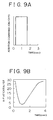
- a predetermined amount of reducing agent is injected into an exhaust port, or the like, for a predetermined period of time, according to a pattern as shown in Fig. 9A, in an attempt to control the air-fuel ratio detected at the NOx catalyst to be substantially equal to the target air-fuel ratio.
- the pattern of Fig. 9A indicates changes in a command signal (ON/OFF signal) applied to an injector for injecting the reducing agent, with time.
- the air-fuel ratio measured at around the NOx catalyst changes as shown in Fig. 9B.
- the air-fuel ratio measured at the NOx catalyst falls far below the target air-fuel ratio that should be close to the stoichiometric value, and is kept in an unnecessarily rich state for a certain period of time. Namely, the air-fuel ratio of the exhaust gas is kept for a while in a low range that is richer than a level required for releasing and reducing NOx.
- the amount of the reducing agent injected to the exhaust port is larger than an amount needed for removing NOx from the NOx catalyst, and therefore an increased amount of reducing agent passes through the NOx catalyst without being used for reducing NOx.
- an HC component contained in the reducing agent may pass through the NOx catalyst, and degrade exhaust emissions.
- an additional measure such as an oxidizing catalyst disposed downstream of the NOx catalyst in the exhaust passage, needs to be taken for removing the HC component that has passed through the NOx catalyst.
- the invention provides an emission control system of an internal combustion engine capable of operating in a lean-burn mode, including (a) a NOx catalyst disposed in an exhaust passage of the engine such that the NOx catalyst absorbs NOx contained in an exhaust gas, and (b) reductant supply means disposed upstream of the NOx catalyst, for adding a reducing agent to the exhaust gas so as to release and reduce NOx absorbed in the NOx catalyst.
- the emission control system further includes (1) load detecting means for detecting a load of the internal combustion engine; (2) calculating means for calculating an amount of the reducing agent that is added in one NOx reducing process, based on the load of the internal combustion engine; and (3) control means for controlling addition of the reducing agent by executing a plurality of reductant adding operations so as to provide the calculated amount of the reducing agent.
- the amount of the reducing agent added for releasing and reducing NOx is controlled depending upon the load of the internal combustion engine. More specifically, the reductant addition amount is increased when the engine operates under a relatively low load, and the same amount is reduced as the engine load increases. In this manner, the reductant addition amount is suitably controlled, taking account of the likelihood of deposition of the reducing agent on walls of an exhaust passage that depend upon the flow velocity and temperature of exhaust gases, so that a sufficient amount of reducing agent can be constantly supplied to the NOx catalyst, irrespective of the engine operating conditions.
- the calculated amount of the reducing agent which has been determined based on the engine load as described above, is added by executing a plurality of reductant adding operations, so that the air-fuel ratio measured at around the NOx catalyst fluctuates between the rich side and the lean side with respect to the stoichiometric value.
- the air-fuel ratio measured at the NOx catalyst is prevented from being kept in an excessively fuel-rich state for an extended period, and the average air-fuel ratio during the addition of the reducing agent is controlled to be sufficiently close to the stoichiometric value.
- the amount of HC passing through the NOx catalyst is advantageously reduced, while at the same time the exhaust air-fuel ratio can be kept at stoichiometric or rich values for a prolonged period of time.
- the reductant addition amount in each of the second and subsequent reductant adding operations is preferably made smaller than that in the first adding operation.
- the reductant addition amount in each of the second and subsequent adding operations may be made smaller than that in the first adding operation, by (1) controlling the period of addition of the reducing agent in each of the second and subsequent adding operations to be shorter than that in the first adding operation, or (2) controlling the pressure at which the reducing agent is added in each of the second and subsequent adding operations to be lower than that in the first adding operation.
- the interval between the first and second reductant adding operations may be made smaller than that between the subsequent adding operations.
- the above-indicated control means controls the second and subsequent reductant adding operations, based on a controlled variable that is corrected based on an air-fuel ratio measured at around the NOx catalyst after the first reductant adding operation is executed.
- the reducing agent can be added with improved accuracy, thus permitting highly efficient exhaust purification.
- control means executes the plurality of reductant adding operations in accordance with a crank angle of the internal combustion engine, so that the reducing agent is added when an exhaust valve of the engine is opened.
- the reducing agent can be surely fed to the NOx catalyst along with a flow of the exhaust gas, thus enabling highly efficient addition of the reducing agent.
- the emission control system the invention further includes determining means for determining whether it is possible to add the reducing agent, depending upon an operating state of the vehicle. For example, it is determined whether the NOx catalyst is held at an activation temperature, or whether the internal combustion engine is in an operating region that permits addition of the reducing agent.
- the reducing agent is supplied when the engine or vehicle conditions allow releasing and reduction of NOx, so that the reducing is prevented from passing through the NOx catalyst without being used for reducing NOx.
- Examples of the internal combustion engine capable of operating in a lean-burn mode, which employs the emission control system of the invention, include lean-burn gasoline engines of direct fuel injection type, and diesel engines.
- the above-indicated load detecting means may detect the engine load, based on an output signal of an accelerator position sensor or a flow rate of intake air that is detected by an air flow meter.
- the NOx catalyst used in the emission control system of the invention may be, for example, an occlusion-reduction type NOx catalyst or a selective-reduction type NOx catalyst.
- the occlusion-reduction type NOx catalyst absorbs NOx when exhaust gas that enters the catalyst has a lean air-fuel ratio, and releases the absorbed NOx and reduces it into N 2 when the oxygen concentration of the exhaust gas is lowered.
- the occlusion-reduction type NOx catalyst includes (a) a support formed of, for example, alumina (Al 2 O 3 ), (b) at least one element carried on the support and selected from alkali metals such as potassium (K), sodium (Na), lithium (Li) and cesium (Cs), alkali earth metals such as barium (Ba) and calcium (Ca), and rare earth metals such as lanthanum (La) and yttrium (Y), and (c) at least one noble metal such as platinum (Pt) also carried on the support.
- alkali metals such as potassium (K), sodium (Na), lithium (Li) and cesium (Cs)
- alkali earth metals such as barium (Ba) and calcium (
- the selective-reduction type NOx catalyst is able to reduce or decompose NOx in the presence of hydrocarbon (HC) under an excess-oxygen atmosphere (i.e., an atmosphere containing an excessive amount of oxygen).
- an excess-oxygen atmosphere i.e., an atmosphere containing an excessive amount of oxygen.
- the selective-reduction type NOx catalyst include (1) a catalyst in which a transition metal, such as Cu, is carried on zeolite through ion exchange, and (2) a catalyst in which a noble metal is carried on zeolite or alumina.
- Examples of the reducing agent used according to the invention may include light oil, gasoline, kerosene, and other substances, which contain hydrocarbon (HC).
- HC hydrocarbon
- an emission control system of an internal combustion engine according to a preferred embodiment of the invention will be described in detail.
- the invention is applied to an emission control system that is employed in a diesel engine adapted for driving a motor vehicle, such as an automobile.
- Fig. 1 shows the construction of the internal combustion engine 1 in the form of a four-cylinder in-line diesel engine, which incorporates an emission control system according to the preferred embodiment of the invention.
- intake air is drawn into a combustion chamber of each cylinder through an intake pipe 3 and an intake manifold 2.
- An air cleaner 4 is provided at one end of the intake pipe 3 at which the intake air is initially drawn into the pipe 3.
- An air flow meter 5, a compressor 6a of a turbocharger 6, an intercooler 7, and a throttle valve 8 are also provided between the opposite ends of the intake pipe 3.
- the air flow meter 5 detects the quantity of new air that flows into the intake pipe 3 through the air cleaner 4, and generates an output signal indicative of the quantity of new air to an electronic control unit (ECU) 9 for controlling the engine 1.
- the ECU 9 then calculates the quantity of intake air, or the flow rate of intake air, based on the output signal of the air flow meter 5.
- the four cylinders of the engine 1 are numbered in the direction from the right to the left as viewed in Fig. 1, as first, second, third and fourth cylinders #1, #2, #3 and #4, respectively.
- Each of the four cylinders of the engine 1 is provided with a fuel injection valve 10, which serves to inject a fuel (e.g., light oil) into a combustion chamber of the corresponding cylinder.
- a fuel e.g., light oil
- Each of the fuel injection valves 10 is connected to a common rail 11 to which fuel is supplied from a fuel pump 12.
- the fuel pump 12 is driven by a crankshaft (not shown) of the engine 1. In operation, the torque generated by the crankshaft is transmitted to an input shaft of the fuel pump 12, and the fuel pump 12 delivers fuel at a pressure that depends upon the transmitted torque.
- the fuel delivered from the fuel pump 12 is supplied via a fuel supply pipe to the common rail 11 at which the pressure of the fuel is raised to a certain level, and is then distributed to the fuel injection valves 10 of the respective cylinders.
- the fuel injection valve 10 is opened, to inject the fuel therefrom.
- the ECU 9 controls the valve opening timing and the valve opening period (or injection period) of each of the fuel injection valves 10 in accordance with operating conditions of the engine 1.
- Exhaust gas produced in the combustion chamber of each cylinder of the engine 1 is discharged into an exhaust manifold 14, and is then emitted to the atmosphere via an exhaust collection pipe 15, an exhaust pipe 16, and a muffler (not illustrated in Fig. 1).
- a portion of the exhaust gas discharged into the exhaust manifold 14 may be recirculated into the intake manifold 2 through an exhaust recirculation pipe 23.
- An EGR cooler 24 and an EGR valve 25 are provided between the opposite ends of the exhaust recirculation pipe 23.
- the ECU 9 controls the opening amount of the EGR valve 25 in accordance with the operating conditions of the engine 1, so as to control the quantity of exhaust gas recirculated into the intake manifold 2.
- a turbine 6b of the turbocharger 6 is provided at one end of the exhaust collection pipe 15 remote from the exhaust manifold 14, and a casing 18 that houses an occlusion-reduction type NOx catalyst 17 (or a lean NOx catalyst) is provided midway the exhaust pipe 16. Furthermore, an air-fuel ratio sensor 26 that generates an electric signal indicative of the air-fuel ratio of exhaust gas flowing through the exhaust pipe 16 is disposed downstream of the casing 18 in the exhaust pipe 16. The turbine 6b, which is driven by the exhaust gas, drives the compressor 6a coupled to the turbine 6b so as to elevate the pressure of the intake air.
- NOx catalyst 17 (which may be simply called “NOx catalyst") received in the casing 18 of the exhaust pipe 16 will be described in detail.
- the occlusion-reduction type NOx catalyst 17 includes (a) a support (support) formed of, for example, alumina (Al 2 O 3 ), (b) at least one element carried on the support and selected from alkali metals such as potassium (K), sodium (Na), lithium (Li) and cesium (Cs), alkali earth metals such as barium (Ba) and calcium (Ca), and rare earth metals such as lanthanum (La) and yttrium (Y), and (c) at least one noble metal such as platinum (Pt) also carried on the support.
- alkali metals such as potassium (K), sodium (Na), lithium (Li) and cesium (Cs)
- alkali earth metals such as barium (Ba) and calcium (Ca)
- rare earth metals such as lanthanum (La) and yttrium (Y)
- Pt platinum
- the NOx catalyst 17 has the function of absorbing and releasing NOx. More specifically, the NOx catalyst 17 absorbs NOx when the air-fuel ratio (which will be called "exhaust air-fuel ratio) of exhaust gas to which the NOx catalyst 17 is exposed is on the lean side of the stoichiometric value, and releases the absorbed NOx in the form of NO 2 or NO when the exhaust air-fuel ratio becomes equal to or richer than the stoichiometric value and the oxygen concentration in the exhaust gas is lowered.
- the NOx (NO 2 or NO) released from the NOx catalyst 17 is immediately reduced into N 2 by reaction with unburned hydrocarbon (HC) and/or carbon monoxide (CO) contained in the exhaust gas. It is thus possible to remove HC, CO and NOx from the exhaust gas by appropriately controlling the exhaust air-fuel ratio.
- HC unburned hydrocarbon
- CO carbon monoxide
- the exhaust air-fuel ratio means the ratio of the total amount of air supplied to the engine 1 to the total amount of fuel (hydrocarbon) supplied to the engine 1.
- the total amount of air or fuel includes those amounts of air or fuel that is supplied to an exhaust passage upstream of the NOx catalyst, engine combustion chambers, an intake passage, and other parts of the engine 1.
- the exhaust air-fuel ratio is equal to the air-fuel ratio of an air-fuel mixture that is supplied to the engine combustion chambers.
- an air-fuel mixture that is normally burned in the combustion chambers is considerably fuel-lean, that is, the air-fuel ratio of the air-fuel mixture to be burned is considerably greater than the stoichiometric value (which is between 14 and 15).
- the air-fuel ratio of exhaust gas that enters the NOx catalyst is considerably lean. In this normal operating state, therefore, NOx contained in the exhaust gas is likely to be absorbed in the NOx catalyst, while only an extremely small amount of NOx is released from the NOx catalyst.
- the air-fuel ratio of an air-fuel mixture supplied to the combustion chambers may be controlled to be stoichiometric or rich, so that the resulting exhaust gas has a stoichiometric or rich air-fuel ratio. In this manner, the oxygen concentration in the exhaust gas is lowered, so that the NOx absorbed in the NOx catalyst can be released from the catalyst.
- a reducing agent needs to be supplied to the exhaust gas so as to lower the oxygen concentration of the exhaust gas, in suitable timing before the NOx absorbing capability of the NOx catalyst gets saturated, so that the NOx absorbed in the NOx catalyst is released and reduced.
- light oil which is used as a fuel of diesel engines, may be used as the reducing agent.
- the ECU 9 of the emission control system of this embodiment estimates the amount of NOx absorbed in the NOx catalyst, based on the past operating state of the engine 1, and causes a flow control valve 22 to open for a certain period of time so as to inject a certain amount of fuel through a fuel injection nozzle 19 when the estimated NOx amount reaches a predetermined value.
- the oxygen concentration in the exhaust gas that enters the NOx catalyst is lowered, and the NOx absorbed in the NOx catalyst is released and reduced into N 2 .
- the internal combustion engine 1 of this embodiment is provided with a reductant supply device that functions to add fuel (e.g., light oil) serving as a reducing agent, to exhaust gas that flows through the exhaust passage located upstream of the NOx catalyst 17.
- the reductant supply device includes the fuel pump 12 and the fuel injection nozzle 19 as mentioned above, a fuel pipe 20, a fuel passage 21, the above-mentioned flow control valve 22, and other components.
- the fuel injection nozzle 19, which serve as a supply port of the reductant supply device, is mounted on a cylinder head 30 of the engine 1, such that the nozzle 19 is exposed to an exhaust port 13 of the first cylinder #1.
- fuel that is pumped from the fuel pump 12 can be supplied to the fuel injection nozzle 19, via the fuel pipe 20 and the fuel passage 21 formed in the cylinder head 30.
- the flow control valve 22 provided midway the fuel pipe 20 serves to control the flow rate or quantity of fuel flowing through the fuel pipe 20, thereby to control the amount of the reducing agent added to the exhaust gas.
- a portion of the fuel pipe 20 that is located upstream of the flow control valve 22 is provided with a shutoff valve 31 for shutting off or cutting flow of fuel through the pipe 20, and a reductant pressure sensor 32 that outputs an electric signal indicative of the pressure within the fuel pipe 20.
- the reductant pressure sensor 32 is disposed between the flow control valve 22 and the shutoff valve 31.
- the fuel injection nozzle 19 is mounted on the cylinder head 30 such that fuel is injected from the nozzle 19 toward the exhaust collection pipe 15.
- a high-pressure fuel delivered from the fuel pump 12 is fed to the fuel injection nozzle 19 through the fuel pipe 20.
- the pressure of the fuel is applied to the fuel injection nozzle 19, and the fuel injection nozzle 19 opens when the fuel pressure reaches a certain valve-opening level, so that the reducing agent is injected through the fuel injection nozzle 19.
- the ECU 9 controls opening and closing of the flow control valve 22, and also controls the opening amount of the flow control valve 22.
- the pressure of the fuel fed to the fuel injection nozzle 19 is raised with an increase in the opening amount of the valve 22, and is lowered with a reduction in the opening amount of the valve 22.
- the exhaust recirculation pipe 23 (which will be abbreviated to "EGR pipe") through which a portion of the exhaust gas is returned to the intake system is connected at one end thereof to a portion of the exhaust manifold 14 that faces the fourth cylinder #4.
- the other end of the EGR pipe 23 is connected to the intake manifold 2.
- the EGR cooler 24 and the EGR valve 25 are provided between the opposite ends of the EGR pipe 23, as described above.
- the ECU 9 controls the opening amount of the EGR valve 25 in accordance with the operating state of the engine 1, so as to control the amount of exhaust gas recirculated.
- the EGR pipe 23, EGR cooler 24 and the EGR valve 25 constitute an exhaust gas recirculation (EGR) system.
- the fuel injection nozzle 19 injects fuel toward the exhaust collection pipe 15 as described above, the fuel added to the exhaust gas smoothly flows into the exhaust collection pipe 15. Furthermore, the fuel injection valve 19 is mounted at the exhaust port 13 of the first cylinder #1, while the EGR pipe 23 is connected to the exhaust manifold 14 at a location in the vicinity of the fourth cylinder #4. This arrangement reduces or eliminates a possibility that the fuel supplied from the fuel injection nozzle 19 is introduced into the EGR pipe 23.
- the ECU 9 has a digital computer including a read-only memory (ROM), a random access memory (ROM), a central processing unit (CPU), an input port and an output port, which are interconnected via a bidirectional bus.
- the ECU 9 performs basic engine control operations, such as an operation to control the amount of fuel injected into the engine 1.
- the ECU 9 receives, at the input port, an input signal from an accelerator position sensor 28 and an input signal from a crank angle sensor 27.
- the accelerator position sensor 28 generates an output voltage that is proportional to the accelerator position (i.e., the amount of depression of the accelerator pedal) to the ECU 9, which in turn calculates the engine load based on the output signal of the accelerator position sensor 28.
- the crank angle sensor 27 generates an output pulse to the ECU 9 each time the crankshaft rotates a predetermined angle, and the ECU 9 calculates the engine speed based on the output pulses.
- the ECU 9 determines the current engine operating state based on the engine load and the engine speed, and calculates a fuel injection amount that is suitable for the current engine operating state, referring to an injection amount map (not shown). The ECU 9 then calculates a valve-opening period of the fuel injection valve 10 that corresponds to the fuel injection amount thus calculated, and controls the operation of the fuel injection valve 10 based on the valve-opening period thus determined.
- the NOx catalyst 17 is disposed in the exhaust passage 16, as described above, and a NOx absorbent carried on the NOx catalyst 17 has the function of absorbing and releasing NOx.
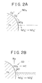
- the mechanism of absorption and reduction of NOx is illustrated in Fig. 2A and Fig. 2B by way of example. While Fig. 2A and Fig. 2B show an example in which platinum Pt and barium Ba are carried on the support of the NOx catalyst 17, similar mechanisms may be provided when other noble metals, alkali metals, alkali earth metals or rare earth metals are used. The mechanism of Fig. 2A and Fig. 2B will be briefly described.
- NO 2 is produced on the surface of platinum Pt, and the NO 2 is kept absorbed into the NOx absorbent to form nitrate ions NO 3 - until the NOx absorbing capability of the NOx absorbent is saturated.
- the air-fuel ratio of exhaust gas produced during normal operations of the engine 1 is fuel-lean, and therefore the NOx absorbent absorbs NOx in the exhaust gas in the normal operating state of the engine 1. If the reducing agent is supplied to the exhaust port located upstream of the NOx catalyst 17, the air-fuel ratio of the exhaust gas that passes through the NOx catalyst 17 turns to be rich, and NOx is released from the NOx absorbent of the catalyst 17 and reduced.
- light oil used as a fuel of the engine 1 is also used as the reducing agent for reducing NOx.
- the use of the light oil is advantageous in view of the storage, replenishment or resupply, and other factors.
- the reducing agent e.g., fuel in this embodiment
- the reducing agent is supplied under various conditions, which include, for example, the pressure under which the reducing agent is supplied or injected, and the period and interval of supply of the reducing agent.
- fuel serving as a reducing agent which is used in one process of releasing and reducing NOx, is added to the exhaust gas a plurality of times, rather than at a time.
- the addition of the fuel is carried out on two or more occasions during one NOx releasing and reducing process, so as to achieve efficient releasing and reduction of NOx.
- This manner of adding the fuel as a reducing agent will be called “multiple-time addition" of the fuel or reductant, when appropriate.
- the amount of the fuel supplied and the implementation of the multiple-time addition of the fuel are controlled in the manners as described below, based on a load condition of the engine 1.
- the ECU 9 initially reads operating conditions of the engine 1. More specifically, the ECU 9 calculates the engine load based on the output signal of the accelerator position sensor 28, and calculates the engine speed based on the output pulses of the crank angle sensor 27. The ECU 9 then determines the engine operating state based on the engine load and the engine speed, and calculates a fuel injection amount that is suitable for the engine operating state, with reference to an injection amount map (not shown).
- the ECU 9 estimates the amount of NOx absorbed in the NOx catalyst, from the past operating state of the engine 1 or the history of the operating state of the engine 1, and causes a fuel as a reducing agent to be injected from the fuel injection nozzle 19 into the exhaust gas when the estimated NOx amount reaches a predetermined value.
- the flow control valve 22 is opened so that a portion of the fuel delivered from the fuel pump 12 is supplied to the fuel injection nozzle 19 through the fuel pipe 20.
- the injection of the fuel in one NOx releasing and reducing process as described above is accomplished by performing a plurality of fuel injecting operations in each of which the fuel is injected by a predetermined amount.
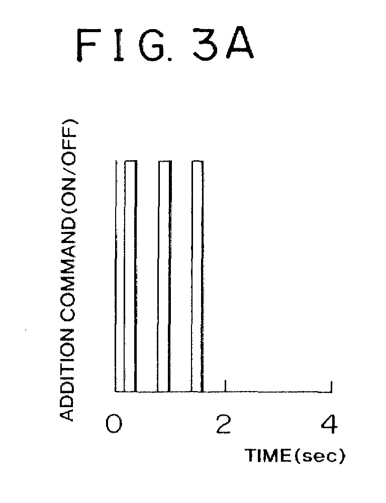
- the ECU 9 controls the flow control valve 22 to open and close intermittently, so that the fuel is injected from the fuel injection nozzle 19 at predetermined time intervals. More specifically, the ECU 9 generates addition commands (or ON/OFF signals) three times as shown in Fig. 3A, so as to open and close the flow control valve 22 in accordance with the commands.
- the fuel injection is carried out at the predetermined intervals such that each fuel injection lasts for a predetermined period of time.
- the air-fuel ratio measured at around the NOx catalyst can be mimetically made equal to the target air-fuel ratio, and ineffective addition of fuel can be suppressed or avoided, resulting in a reduced amount of HC passing through the NOx catalyst 17. Furthermore, the air-fuel ratio at the NOx catalyst can be kept close to the stoichiometric value for an extended period of time, so that NOx can be removed with improved efficiency.
- the fuel injection is performed a plurality of times, such that the amount of the fuel added in the second and subsequent fuel injecting operations is smaller than that added in the first fuel injecting operation.
- substantially the same amount of the fuel is added in the three injecting operations during the multiple-time fuel injection. If the air-fuel ratio is made rich by the initial fuel injection, and the next fuel injection is then executed before the air-fuel ratio returns completely to the original lean value, as illustrated in Fig. 4 by way of example, the resulting air-fuel ratio becomes excessively rich since fuel-rich exhaust gases are successively fed to the NOx catalyst 17. In this case, the amount of the fuel which is not effective to reduce NOx is increased, and HC contained in the fuel may pass through the NOx catalyst 17 without being consumed at the NOx catalyst 17.
- the ECU 9 may control the flow control valve 22, for example, so as to inject the fuel for a relatively long period of time in the first injecting operation, and reduce the fuel injection period for the second and subsequent injecting operations.
- Other means or methods may be employed for controlling the amount of the fuel injected in the second and following injecting operations to be smaller than that injected in the first injecting operation.
- the fuel is injected at a relatively high pressure in the initial injecting operation, and the pressure at which the fuel is injected is lowered for the second and subsequent injecting operations.
- the interval between the first and second injecting operations is made shorter than that between the injecting operations following the first injecting operation.
- Fig. 5A through Fig. 5D indicate various patterns of addition of the fuel.
- the ECU 9 controls the flow control valve 22 in accordance with a fuel addition pattern selected from the patterns of Fig. 5A to Fig. 5D that are stored in advance in the ROM.
- the size of a nozzle hole of the fuel injection nozzle 19, which is made variable, is controlled to be relatively large during the first injecting operation, and the size of the nozzle hole is reduced for the second and subsequent injecting operations.
- the fuel is injected for a relatively long period of time in the first injecting operation, and the period of injection of the fuel (which may also called "fuel injection time") is reduced for the second and subsequent injecting operations.
- the initial interval between the first and second injecting operations is relatively large, and the interval between two successive injecting operations following the first injecting operation is reduced as compared with the initial interval.
- the interval between two successive injecting operations is defined as a period of time between the start of injection of the fuel in one fuel injecting operation and the start of injection of the fuel in the next injecting operation that occurs right after the above-indicated one injecting operation.
- the flow control valve 22 is opened for a relatively long period of time in the first fuel injecting operation, and the valve-opening period of the flow control valve 22 is reduced for the second and subsequent injecting operations.
- the fuel is injected at a relatively high pressure in the first injecting operation, and the pressure at which the fuel is injected is lowered for the second and subsequent injecting operations.
- the interval between two successive injecting operations is constant. If the pressure at which the fuel is injected is increased, an increased amount of fuel is injected from the fuel injection nozzle 19. Thus, within the same period of injection of the fuel, the amount of the fuel injected increases with an increase in the fuel injection pressure.
- the flow control valve 22 is fully opened during the first fuel injecting operation, so that the pressure in the fuel passage 21 is kept high, and the opening amount of the flow control valve 22 is reduced in the second and subsequent injecting operations, so that the fuel injection pressure at the fuel injection nozzle 19 is lowered.
- the interval between the first and second fuel injecting operations is made shorter than that between the second and third injecting operations.
- the flow control valve 22 is opened in the second injecting operation upon a lapse of a relatively short time after the flow control valve 22 is closed at the end of the first injecting operation. Subsequently, the flow control valve 22 is closed for a relatively long time between two successive injecting operations.
- the patterns of Figs. 5A, 5B, 5C and Fig. 5D are stored in the ROM of the ECU 9, and the control operations according to these patterns may be performed as needed, depending upon the engine operating conditions, such as the engine load. If possible, two or more of these control operations may be carried out in combination. For example, the fuel is injected at a relatively high pressure for a relatively long period of time in the first injecting operation, and the fuel injection pressure is lowered and the fuel injection time is shortened for the second and subsequent injecting operations.
- the air-fuel ratio measured at the NOx catalyst 17 can be controlled to be mimetically close to the target air-fuel ratio, which leads to a reduction in the amount of fuel that is not effective to reduce NOx absorbed in the NOx absorbent.
- fuel addition control is executed after the first injecting operation.
- the fuel injection amount, fuel injection time, injection interval, or the like, associated with the second and subsequent injecting operations is corrected based on an engine operating state (such as A/F ratio) detected after the first injecting operation, as schematically shown in Fig. 6.
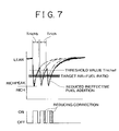
- the amount of the fuel injected in the second and subsequent fuel injecting operations is controlled to a value that is corrected based on the air-fuel ratio that is generated from the air-fuel ratio sensor 26 located downstream of the NOx catalyst 17 after the first injecting operation, as shown in Fig. 7.
- the ECU 9 initially calculates the amount of addition of the fuel required for making the air-fuel ratio at the NOx catalyst 17 substantially equal to the target air-fuel ratio, based on the engine speed Ne and the fuel injection amount Qfin.
- the base fuel injection time ⁇ b of the first injecting operation is determined based on the engine speed Ne and the fuel injection amount Qfin, and the interval Tintml between two successive injecting operations in the multiple-time addition is determined in accordance with the target air-fuel ratio, based on the base fuel injection time ⁇ b.
- the base rich time Trichb corresponding to the base injection time ⁇ b is calculated.
- the set number of the fuel injecting operations to be executed in the multiple-time addition is determined so that the total amount of fuel injected during the multiple-time fuel addition becomes equal to a predetermined value (i.e., the calculated amount of fuel as indicated above).
- the base fuel injection time ⁇ b is defined as a basic period of time in which the fuel injection nozzle 19 is held opened and the fuel is injected from the nozzle 19.
- the interval Tintml of the multiple-time fuel addition is defined as a time interval between the start of one fuel injecting operation and the start of the next fuel injecting operation.
- the base rich time Trichb is defined as a period of time during which the air-fuel ratio is in a richer region with respect to a threshold value Trichaf (namely, the air-fuel ratio is richer than the threshold value Trichaf) as a result of a single fuel injecting operation.
- the ECU 9 executes the first injecting operation by opening the flow control valve 22, and compares the air-fuel ratio generated from the air-fuel sensor 26 after the fuel injection, with the threshold value Trichaf.
- the threshold value Trichaf which is higher (i.e., leaner) than the target air-fuel ratio close to the stoichiometric value, is defined as a boundary value of the air-fuel ratio that is at least required for the NOx catalyst 17 to release and reduce NOx by rich spikes.
- the ECU 9 increases the rich time Trich in the next injecting operation so that the resulting air-fuel ratio becomes richer than the threshold value Trichaf.
- the ECU 9 executes the next fuel injecting operation, and compares the air-fuel ratio generated by the air-fuel ratio sensor 26 with the threshold value Trichaf again. If the output of the air-fuel ratio sensor 26 is richer than the threshold value Trichaf, the rich time Trich of the second and subsequent fuel injecting operations is compared with the base rich time Trichb of the first injecting operation, and the base fuel injection time ⁇ b is corrected depending upon the result of the comparison. If the comparison between the base rich time Trichb and the rich time Trich indicates that the rich time Trich is equal to or greater than the base rich time Trichb, the base fuel injection time ⁇ b for the following injecting operations is reduced.
- the rich time Trich is less than the base rich time Trichb, on the other hand, the base injection time ⁇ b for the following injecting operations is increased. With this correction, the ECU 9 resets the rich time Trich. If all of the fuel injecting operations in the multiple-time fuel addition have not yet been finished, the next fuel injection is performed based on the reset rich time Trich.
- the rich time Trich in the second and subsequent injecting operations is accordingly reduced to a certain length, and the richest air-fuel ratio (Richpeak in Fig. 7) that can be achieved during each fuel injection is kept at substantially the same level. If the above correction is not made, the richest air-fuel ratio (Richpeak) continues to be richer for each fuel injecting operation as shown in Fig. 4, which means an excessively large amount of fuel added to the exhaust gas.
- the richest values (Richpeak) of the air-fuel ratio as indicated in Fig. 7 may be used for the correction of the base fuel injection time ⁇ b.
- the rich peak value of the air-fuel ratio is integrated upon each fuel injecting operation, and, when the integrated value exceeds a predetermined value, the base injection time ⁇ b is corrected to be reduced, depending upon the degree by which the integrated value exceeds the predetermined value.
- a value obtained by subtracting the threshold value Trichaf from the output of the air-fuel ratio sensor 26 may be used for the correction of the base injection time ⁇ b.
- the above-indicated value is integrated upon each fuel injecting operation, and, when the integrated value exceeds a predetermined value, the base fuel injection time ⁇ b is corrected to be reduced, depending upon the degree by which the integrated value exceeds the predetermined value.
- the air-fuel ratio is changed or shifted to the lean side during a period between one fuel injecting operation and the next fuel injecting operation, in which no fuel is added to the exhaust gas.
- the most fuel-lean value of the air-fuel ratio that can be achieved during this period is kept substantially constant with respect to the multiple fuel injecting operations.
- the air-fuel ratio fluctuates between the lean side and the rich side of the target air-fuel ratio, such that the average air-fuel ratio is made substantially close to the target air-fuel ratio.
- the fuel as a reducing agent is prevented from passing through the NOx catalyst 17. Furthermore, the multiple-time fuel injection can be carried out with improved accuracy, due to feedback control performed based on the actual air-fuel ratio generated from the air-fuel ratio sensor 26 after fuel injection, thus assuring highly efficient removal of NOx.
- the fuel addition control as described is executed according to a fuel addition routine as illustrated in Fig. 8.
- This control routine is stored in advance in the ROM of the ECU 9, and is repeatedly executed by the CPU.
- the fuel addition control will be now described with reference to the routine of Fig. 8.
- Step 100 is initially executed to determine the base fuel injection time ⁇ b of the first injecting operation and the multiple-time injection interval Tintml, based on the engine speed Ne and the fuel injection amount Qfin. Also determined in step 100 are the base rich time Trichb corresponding to the base injection time ⁇ b, and the set number of fuel injecting operations required for making the total amount of the added fuel substantially equal to a predetermined amount.
- step 101 the first injecting operation is performed in which the fuel serving as a reducing agent is injected from the fuel injection nozzle 19 under the above-described conditions.
- step 102 is executed to compare the output value of the air-fuel ratio sensor 26 after the fuel injection with the threshold value Trichaf. If the air-fuel ratio generated from the air-fuel ratio sensor 26 is leaner than the threshold value Trichaf, the control process proceeds to step 103.
- step 103 the rich time Trich for the second and subsequent injecting operations is increased so that the air-fuel ratio becomes richer than the threshold value Trichaf.
- Step 104 is then executed to determine whether the rich time Trich is greater than the multiple-time injection interval Tintml. If the rich time Trich is greater than the multiple-time injection interval Tintml, the control process proceeds to step 105 in which further fuel addition is inhibited assuming that the exhaust gas will be in an excessively rich state, or the fuel injector, calculating means, or the like, is determined as being at fault.
- step 104 If it is determined in step 104 that the rich time Trich is shorter than the multiple-time injection interval Tintml, the next fuel injecting operation is carried out, and then the air-fuel ratio received from the air-fuel ratio sensor 26 is compared with the threshold value Trichaf. If the output of the air-fuel ratio sensor 26 is richer than the threshold value Trichaf, the control process proceeds to step 106 in which the rich time Trich of the subsequent injecting operations is compared with the base rich time Trichab (i.e., the rich time Trich in the last cycle) of the first injecting operation.
- the rich time Trich of the subsequent injecting operations is compared with the base rich time Trichab (i.e., the rich time Trich in the last cycle) of the first injecting operation.
- step 108 the control process proceeds to step 108 in which the base fuel injection time ⁇ b is corrected to be reduced, and step 109 is then executed to reset the rich time Trich. If the rich time Trich is equal to or greater than the base rich time Trichb, on the other hand, the base injection time ⁇ b is corrected to be increased, and step 109 is then executed to reset the rich time Trich.
- step 110 it is determined whether the set number of fuel injecting operations have been carried out. If a negative decision (NO) is obtained in step 110, the control process returns to step 101 in which the fuel is injected from the fuel injection nozzle 19.
- the amount of the fuel added in the second and subsequent injecting operations is corrected based on the air-fuel ratio outputted from the air-fuel ratio sensor 27 located downstream of the NOx catalyst 17 after the first injecting operation, thus assuring improved accuracy in the addition of the fuel to the exhaust gas.
- the invention is applied to a diesel engine in the illustrated embodiment, the invention is equally applicable to gasoline engines capable of operating in a lean-burn mode.
- the ECU 9 controls the timing of fuel injection from the fuel injection nozzle 19, to be in synchronism with the timing of opening of exhaust valves (not shown) through which exhaust gas is emitted from the respective cylinders into the exhaust manifold 14, in accordance with rotation of the engine 1 as represented by the signal from the crank angle sensor 27.
- the fuel injected from the fuel injection nozzle 19 can flow along with the exhaust gas emitted from the cylinders, through the exhaust collection pipe 15 and the exhaust pipe 16.
- the added fuel is less likely to be deposited on the walls of the exhaust collection pipe 15 and the exhaust pipe 16. Consequently, the added fuel reaches the NOx catalyst 17 without fail, and effectively reduces and releases NOx absorbed in the NOx absorbent of the catalyst 17.
- An emission control system of an lean-burn internal combustion engine (1) includes a NOx catalyst (17), and a reductant supply device (12, 19, 20, 21, 22) disposed upstream of the NOx catalyst for adding a reducing agent so as to release and reduce NOx absorbed in the NOx catalyst.
- the emission control system detects an engine load, and calculates an amount of the reducing agent that is added in one NOx reducing process, based on the engine load. The system then executes a plurality of reductant adding operations in a controlled manner so as to provide the calculated amount of the reducing agent.
Landscapes
- Engineering & Computer Science (AREA)
- Chemical & Material Sciences (AREA)
- Combustion & Propulsion (AREA)
- Mechanical Engineering (AREA)
- General Engineering & Computer Science (AREA)
- Chemical Kinetics & Catalysis (AREA)
- Health & Medical Sciences (AREA)
- Toxicology (AREA)
- Exhaust Gas After Treatment (AREA)
- Exhaust Gas Treatment By Means Of Catalyst (AREA)
Abstract
Description
Claims (22)
- An emission control system of an internal combustion engine (1) capable of operating in a lean-burn mode, including (a) a NOx catalyst (17) disposed in an exhaust passage (16) of the internal combustion engine, such that the NOx catalyst absorbs NOx contained in an exhaust gas, and (b) reductant supply means (12, 19, 20, 21, 22) disposed upstream of the NOx catalyst, for adding a reducing agent to the exhaust gas so as to release and reduce NOx absorbed in the NOx catalyst, characterized by further comprising:load detecting means (5, 28) for detecting a load of the internal combustion engine;calculating means for calculating an amount of the reducing agent that is added in one NOx reducing process, based on the load of the internal combustion engine; andcontrol means for controlling addition of the reducing agent by executing a plurality of reductant adding operations so as to provide the calculated amount of the reducing agent.
- An emission control system according to claim 1, further comprising means for determining whether it is possible to add the reducing agent, depending upon an operating state of a vehicle having the internal combustion engine.
- An emission control system according to claim 1 or claim 2, wherein the control means controls an amount of the reducing agent added in each of the plurality of reductant adding operations, such that the amount of the reducing agent added in a first reductant adding operation is made smaller than that of the reducing agent added in each of second and subsequent reductant adding operations.
- An emission control system according to any one of claims 1 to 3, wherein the control means controls a period of time during which the reducing agent is added in each of the plurality of reductant adding operations, such that the period of addition of the reducing agent in a first reductant adding operation is made longer than that of the reducing agent in each of second and subsequent reductant adding operations.
- An emission control system according to any one of claims 1 to 4, wherein the control means controls a pressure at which the reducing agent is added in each of the plurality of reductant adding operations, such that the pressure at which the reducing agent is added in a first reductant adding operation is made higher than that at which the reducing agent is added in each of second and subsequent reductant adding operations.
- An emission control system according to any one of claims 1 to 5, wherein the control means controls an interval between two successive ones of the plurality of reductant adding operations, such that the interval between first and second reductant adding operations is made shorter than that between subsequent reductant adding operations.
- An emission control system according to any one of claims 1 to 6, wherein the control means controls second and subsequent ones of the plurality of reductant adding operations, based on a controlled variable that is corrected based on an air-fuel ratio measured at around the NOx catalyst after a first reductant adding operation is executed.
- An emission control system according to claim 7, wherein the controlled variable is a period of time during which the reducing agent is added in each of the plurality of reductant adding operations.
- An emission control system according to claim 1 or claim 2, wherein the plurality of reductant adding operations are executed at predetermined time intervals such that a predetermined amount of the reducing agent is added for a predetermined period of time in each of the reductant adding operations.
- An emission control system according to any one of claims 1 to 9, wherein the control means executes the plurality of reductant adding operations in accordance with a crank angle of the internal combustion engine, so that the reducing agent is added when an exhaust valve of the engine is opened.
- An emission control system according to any one of claims 1 to 10, wherein the load detecting means detects the load, based on at least one of an output signal of an accelerator position sensor (28) and a flow rate of intake air that is detected by an air flow meter (5).
- A method for purifying an exhaust gas emitted from an internal combustion engine (1) capable of operating in a lean-burn mode, the internal combustion engine being provided with (a) a NOx catalyst (17) disposed in an exhaust passage (16) such that the NOx catalyst absorbs NOx contained in the exhaust gas, and (b) a reductant supply device (12, 19, 20, 21, 22) disposed upstream of the NOx catalyst, for adding a reducing agent to the exhaust gas so as to release and reduce NOx absorbed in the NOx catalyst, comprising the steps of:detecting a load of the internal combustion engine;calculating an amount of the reducing agent that is added in one NOx reducing process, based on the load of the internal combustion engine; andcontrolling addition of the reducing agent by executing a plurality of reductant adding operations so as to provide the calculated amount of the reducing agent.
- A method according to claim 12, further comprising a step of determining whether it is possible to add the reducing agent, depending upon an operating state of a vehicle having the internal combustion engine.
- A method according to claim 12 or claim 13, wherein an amount of the reducing agent added in each of the plurality of reductant adding operations is controlled such that the amount of the reducing agent added in a first reductant adding operation is made smaller than that of the reducing agent added in each of second and subsequent reductant adding operations.
- A method according to any one of claims 12 to 14, wherein a period of time during which the reducing agent is added in each of the plurality of reductant adding operations is controlled such that the period of addition of the reducing agent in a first reductant adding operation is made longer than that of the reducing agent in each of second and subsequent reductant adding operations.
- A method according to any one of claims 12 to 15, wherein a pressure at which the reducing agent is added in each of the plurality of reductant adding operations is controlled such that the pressure at which the reducing agent is added in a first reductant adding operation is made higher than that at which the reducing agent is added in each of second and subsequent reductant adding operations.
- A method according to any one of claims 12 to 16, wherein an interval between two successive ones of the plurality of reductant adding operations is controlled such that the interval between first and second reductant adding operations is made shorter than that between subsequent reductant adding operations.
- A method according to any one of claims 12 to 17, wherein second and subsequent ones of the plurality of reductant adding operations are controlled based on a controlled variable that is corrected based on an air-fuel ratio measured at around the NOx catalyst after a first reductant adding operation is executed.
- A method according to claim 18, wherein the controlled variable is a period of time during which the reducing agent is added in each of the plurality of reductant adding operations.
- A method according to claim 12 or claim 13, wherein the plurality of reductant adding operations are executed at predetermined time intervals such that a predetermined amount of the reducing agent is added for a predetermined period of time in each of the reductant adding operations.
- A method according to any one of claims 12 to 20, wherein the plurality of reductant adding operations are executed in accordance with a crank angle of the internal combustion engine, so that the reducing agent is added when an exhaust valve of the engine is opened.
- A method according to any one of claims 12 to 21, wherein the load of the internal combustion engine is detected based on at least one of an output signal of an accelerator position sensor (28) and a flow rate of intake air that is detected by an air flow meter (5).
Applications Claiming Priority (4)
| Application Number | Priority Date | Filing Date | Title |
|---|---|---|---|
| JP2000223051 | 2000-07-24 | ||
| JP2000223051 | 2000-07-24 | ||
| JP2001212889 | 2001-07-12 | ||
| JP2001212889A JP3508744B2 (en) | 2000-07-24 | 2001-07-12 | Exhaust gas purification device for internal combustion engine |
Publications (3)
| Publication Number | Publication Date |
|---|---|
| EP1176289A2 true EP1176289A2 (en) | 2002-01-30 |
| EP1176289A3 EP1176289A3 (en) | 2003-04-16 |
| EP1176289B1 EP1176289B1 (en) | 2004-04-28 |
Family
ID=26596588
Family Applications (1)
| Application Number | Title | Priority Date | Filing Date |
|---|---|---|---|
| EP01117845A Expired - Lifetime EP1176289B1 (en) | 2000-07-24 | 2001-07-23 | Emission control system of internal combustion engine |
Country Status (4)
| Country | Link |
|---|---|
| EP (1) | EP1176289B1 (en) |
| JP (1) | JP3508744B2 (en) |
| KR (1) | KR100441482B1 (en) |
| DE (1) | DE60102985T2 (en) |
Cited By (8)
| Publication number | Priority date | Publication date | Assignee | Title |
|---|---|---|---|---|
| US6928359B2 (en) * | 2001-08-09 | 2005-08-09 | Ford Global Technologies, Llc | High efficiency conversion of nitrogen oxides in an exhaust aftertreatment device at low temperature |
| FR2871514A1 (en) * | 2004-06-14 | 2005-12-16 | Toyota Motor Co Ltd | Regulatory system for regeneration of purification unit in exhaust system of internal combustion engine comprises sensors in exhaust pipe which detect flow rate of circulating gases, and command device controlling time of supply of fuel |
| US8074446B2 (en) | 2006-07-12 | 2011-12-13 | Toyota Jidosha Kabushiki Kaisha | Exhaust gas purification system for internal combustion engine |
| CN102713186A (en) * | 2010-01-18 | 2012-10-03 | 斯堪尼亚商用车有限公司 | Device and method for improving the performance of a motor vehicle |
| EP2987977A1 (en) * | 2014-08-19 | 2016-02-24 | Toyota Jidosha Kabushiki Kaisha | Control system and control method of internal combustion engine |
| US9828899B2 (en) | 2013-09-30 | 2017-11-28 | Isuzu Motors Limited | Exhaust gas purification system and exhaust gas purification method |
| CN110520222A (en) * | 2017-03-29 | 2019-11-29 | 康明斯排放处理公司 | Assembly and method for NOx reductant dosing using variable injection angle nozzles |
| CN113914974A (en) * | 2020-07-08 | 2022-01-11 | 长城汽车股份有限公司 | Method and device for reducing emission of nitrogen oxides and automobile |
Families Citing this family (6)
| Publication number | Priority date | Publication date | Assignee | Title |
|---|---|---|---|---|
| DE102004048075A1 (en) * | 2004-10-02 | 2006-04-06 | Robert Bosch Gmbh | Dosing system for pollutant reduction in automotive exhaust gases |
| JP4577039B2 (en) * | 2005-02-18 | 2010-11-10 | トヨタ自動車株式会社 | Exhaust gas purification device for internal combustion engine |
| JP4781031B2 (en) * | 2005-07-19 | 2011-09-28 | トヨタ自動車株式会社 | Control device for exhaust purification system |
| JP4654880B2 (en) * | 2005-11-01 | 2011-03-23 | トヨタ自動車株式会社 | Exhaust gas purification system for internal combustion engine |
| JP2007315277A (en) | 2006-05-25 | 2007-12-06 | Toyota Motor Corp | Exhaust gas purification system for V-type 8-cylinder internal combustion engine |
| CN103003690A (en) | 2010-06-23 | 2013-03-27 | 丰田自动车株式会社 | Fault diagnosis system for gas sensor |
Family Cites Families (8)
| Publication number | Priority date | Publication date | Assignee | Title |
|---|---|---|---|---|
| JPH05263624A (en) * | 1992-03-19 | 1993-10-12 | Mitsubishi Motors Corp | Exhaust emission control device for diesel engine |
| JP2845103B2 (en) * | 1992-09-28 | 1999-01-13 | トヨタ自動車株式会社 | Exhaust gas purification device for internal combustion engine |
| JPH08260947A (en) * | 1995-03-28 | 1996-10-08 | Nissan Diesel Motor Co Ltd | Emission control device of diesel engine |
| DE19639172C2 (en) * | 1996-09-24 | 2001-11-08 | Siemens Ag | Direct fuel injection method for a diesel internal combustion engine |
| JP3799758B2 (en) * | 1997-08-05 | 2006-07-19 | トヨタ自動車株式会社 | Catalyst regeneration device for internal combustion engine |
| JP2000110643A (en) | 1998-10-06 | 2000-04-18 | Toyota Motor Corp | Fuel injection device for internal combustion engine |
| JP3985083B2 (en) * | 1998-09-29 | 2007-10-03 | マツダ株式会社 | Diesel engine exhaust purification system |
| JP2000257419A (en) | 1999-03-03 | 2000-09-19 | Toyota Motor Corp | Exhaust gas purification method and device |
-
2001
- 2001-07-12 JP JP2001212889A patent/JP3508744B2/en not_active Expired - Lifetime
- 2001-07-23 KR KR10-2001-0044120A patent/KR100441482B1/en not_active Expired - Lifetime
- 2001-07-23 EP EP01117845A patent/EP1176289B1/en not_active Expired - Lifetime
- 2001-07-23 DE DE60102985T patent/DE60102985T2/en not_active Expired - Lifetime
Cited By (11)
| Publication number | Priority date | Publication date | Assignee | Title |
|---|---|---|---|---|
| US6928359B2 (en) * | 2001-08-09 | 2005-08-09 | Ford Global Technologies, Llc | High efficiency conversion of nitrogen oxides in an exhaust aftertreatment device at low temperature |
| FR2871514A1 (en) * | 2004-06-14 | 2005-12-16 | Toyota Motor Co Ltd | Regulatory system for regeneration of purification unit in exhaust system of internal combustion engine comprises sensors in exhaust pipe which detect flow rate of circulating gases, and command device controlling time of supply of fuel |
| US7441402B2 (en) | 2004-06-14 | 2008-10-28 | Toyota Jidosha Kabushiki Kaisha | Exhaust gas control apparatus and exhaust gas control method for internal combustion engine |
| US8074446B2 (en) | 2006-07-12 | 2011-12-13 | Toyota Jidosha Kabushiki Kaisha | Exhaust gas purification system for internal combustion engine |
| CN102713186A (en) * | 2010-01-18 | 2012-10-03 | 斯堪尼亚商用车有限公司 | Device and method for improving the performance of a motor vehicle |
| CN102713186B (en) * | 2010-01-18 | 2014-09-17 | 斯堪尼亚商用车有限公司 | Device and method for improving the performance of a motor vehicle |
| RU2539239C2 (en) * | 2010-01-18 | 2015-01-20 | Сканиа Св Аб | Device and method to improve vehicle performance |
| US9828899B2 (en) | 2013-09-30 | 2017-11-28 | Isuzu Motors Limited | Exhaust gas purification system and exhaust gas purification method |
| EP2987977A1 (en) * | 2014-08-19 | 2016-02-24 | Toyota Jidosha Kabushiki Kaisha | Control system and control method of internal combustion engine |
| CN110520222A (en) * | 2017-03-29 | 2019-11-29 | 康明斯排放处理公司 | Assembly and method for NOx reductant dosing using variable injection angle nozzles |
| CN113914974A (en) * | 2020-07-08 | 2022-01-11 | 长城汽车股份有限公司 | Method and device for reducing emission of nitrogen oxides and automobile |
Also Published As
| Publication number | Publication date |
|---|---|
| KR20020008792A (en) | 2002-01-31 |
| KR100441482B1 (en) | 2004-07-23 |
| EP1176289B1 (en) | 2004-04-28 |
| DE60102985D1 (en) | 2004-06-03 |
| JP3508744B2 (en) | 2004-03-22 |
| DE60102985T2 (en) | 2005-05-04 |
| EP1176289A3 (en) | 2003-04-16 |
| JP2002106332A (en) | 2002-04-10 |
Similar Documents
| Publication | Publication Date | Title |
|---|---|---|
| US7073325B2 (en) | Exhaust emission control method and system | |
| EP1304457B1 (en) | Exhaust emission control device of internal combustion engine | |
| EP1108876B1 (en) | Internal combustion engine | |
| US8037675B2 (en) | Exhaust gas purification system for internal combustion engine and method for exhaust gas purification | |
| EP1302647B1 (en) | Exhaust gas purification system for internal combustion engine | |
| EP1176289B1 (en) | Emission control system of internal combustion engine | |
| EP2063077B1 (en) | Exhaust purification device for internal combustion engine | |
| EP1176290B1 (en) | Exhaust gas purification device for internal combustion engine | |
| JP2002242663A (en) | Exhaust gas purification device for internal combustion engine | |
| EP1176298B1 (en) | Emission control system and method for internal combustion engine | |
| JP2002038942A (en) | Exhaust gas purification device for internal combustion engine | |
| JP2002030927A (en) | Exhaust gas purification device for internal combustion engine | |
| US8534048B2 (en) | Exhaust purification system of internal combustion engine | |
| JP4107137B2 (en) | Exhaust gas purification device for internal combustion engine | |
| JP2002038941A (en) | Exhaust gas purification device for internal combustion engine | |
| JP4001045B2 (en) | Exhaust gas purification device for internal combustion engine | |
| JPH11229864A (en) | Exhaust gas purification device for internal combustion engine | |
| JP2004232555A (en) | Exhaust gas purification system for internal combustion engine | |
| JP2002038925A (en) | Exhaust gas purification device for internal combustion engine | |
| JP2000170525A (en) | Exhaust gas purification device for internal combustion engine | |
| JP2002195085A (en) | Exhaust purification device for internal combustion engine having injection timing correction function |
Legal Events
| Date | Code | Title | Description |
|---|---|---|---|
| PUAI | Public reference made under article 153(3) epc to a published international application that has entered the european phase |
Free format text: ORIGINAL CODE: 0009012 |
|
| 17P | Request for examination filed |
Effective date: 20010723 |
|
| AK | Designated contracting states |
Kind code of ref document: A2 Designated state(s): AT BE CH CY DE DK ES FI FR GB GR IE IT LI LU MC NL PT SE TR |
|
| AX | Request for extension of the european patent |
Free format text: AL;LT;LV;MK;RO;SI |
|
| PUAL | Search report despatched |
Free format text: ORIGINAL CODE: 0009013 |
|
| AK | Designated contracting states |
Designated state(s): AT BE CH CY DE DK ES FI FR GB GR IE IT LI LU MC NL PT SE TR |
|
| AX | Request for extension of the european patent |
Extension state: AL LT LV MK RO SI |
|
| RIC1 | Information provided on ipc code assigned before grant |
Ipc: 7B 01D 53/94 B Ipc: 7F 01N 3/20 B Ipc: 7F 01N 3/08 A Ipc: 7F 01N 3/36 B Ipc: 7F 02D 41/02 B |
|
| 17Q | First examination report despatched |
Effective date: 20030602 |
|
| GRAP | Despatch of communication of intention to grant a patent |
Free format text: ORIGINAL CODE: EPIDOSNIGR1 |
|
| AKX | Designation fees paid |
Designated state(s): DE FR GB |
|
| GRAS | Grant fee paid |
Free format text: ORIGINAL CODE: EPIDOSNIGR3 |
|
| GRAA | (expected) grant |
Free format text: ORIGINAL CODE: 0009210 |
|
| AK | Designated contracting states |
Kind code of ref document: B1 Designated state(s): DE FR GB |
|
| REG | Reference to a national code |
Ref country code: GB Ref legal event code: FG4D |
|
| REG | Reference to a national code |
Ref country code: IE Ref legal event code: FG4D |
|
| REF | Corresponds to: |
Ref document number: 60102985 Country of ref document: DE Date of ref document: 20040603 Kind code of ref document: P |
|
| ET | Fr: translation filed | ||
| PLBE | No opposition filed within time limit |
Free format text: ORIGINAL CODE: 0009261 |
|
| STAA | Information on the status of an ep patent application or granted ep patent |
Free format text: STATUS: NO OPPOSITION FILED WITHIN TIME LIMIT |
|
| 26N | No opposition filed |
Effective date: 20050131 |
|
| REG | Reference to a national code |
Ref country code: IE Ref legal event code: MM4A |
|
| REG | Reference to a national code |
Ref country code: GB Ref legal event code: 746 Effective date: 20130412 |
|
| REG | Reference to a national code |
Ref country code: DE Ref legal event code: R084 Ref document number: 60102985 Country of ref document: DE Effective date: 20130410 |
|
| REG | Reference to a national code |
Ref country code: FR Ref legal event code: PLFP Year of fee payment: 16 |
|
| REG | Reference to a national code |
Ref country code: FR Ref legal event code: PLFP Year of fee payment: 17 |
|
| REG | Reference to a national code |
Ref country code: FR Ref legal event code: PLFP Year of fee payment: 18 |
|
| PGFP | Annual fee paid to national office [announced via postgrant information from national office to epo] |
Ref country code: FR Payment date: 20200612 Year of fee payment: 20 |
|
| PGFP | Annual fee paid to national office [announced via postgrant information from national office to epo] |
Ref country code: GB Payment date: 20200716 Year of fee payment: 20 Ref country code: DE Payment date: 20200707 Year of fee payment: 20 |
|
| REG | Reference to a national code |
Ref country code: DE Ref legal event code: R071 Ref document number: 60102985 Country of ref document: DE |
|
| REG | Reference to a national code |
Ref country code: GB Ref legal event code: PE20 Expiry date: 20210722 |
|
| PG25 | Lapsed in a contracting state [announced via postgrant information from national office to epo] |
Ref country code: GB Free format text: LAPSE BECAUSE OF EXPIRATION OF PROTECTION Effective date: 20210722 |