EP1176102A2 - High gas barrier asymmetric liner and closure - Google Patents
High gas barrier asymmetric liner and closure Download PDFInfo
- Publication number
- EP1176102A2 EP1176102A2 EP01306087A EP01306087A EP1176102A2 EP 1176102 A2 EP1176102 A2 EP 1176102A2 EP 01306087 A EP01306087 A EP 01306087A EP 01306087 A EP01306087 A EP 01306087A EP 1176102 A2 EP1176102 A2 EP 1176102A2
- Authority
- EP
- European Patent Office
- Prior art keywords
- layer
- closure
- liner
- group
- gas barrier
- Prior art date
- Legal status (The legal status is an assumption and is not a legal conclusion. Google has not performed a legal analysis and makes no representation as to the accuracy of the status listed.)
- Withdrawn
Links
- 230000004888 barrier function Effects 0.000 title claims abstract description 78
- 229920000106 Liquid crystal polymer Polymers 0.000 claims abstract description 61
- 239000004977 Liquid-crystal polymers (LCPs) Substances 0.000 claims abstract description 61
- 239000010410 layer Substances 0.000 claims description 172
- -1 polyethylene Polymers 0.000 claims description 26
- 229920000098 polyolefin Polymers 0.000 claims description 22
- 239000005038 ethylene vinyl acetate Substances 0.000 claims description 21
- 239000000463 material Substances 0.000 claims description 20
- 229920001200 poly(ethylene-vinyl acetate) Polymers 0.000 claims description 20
- DQXBYHZEEUGOBF-UHFFFAOYSA-N but-3-enoic acid;ethene Chemical compound C=C.OC(=O)CC=C DQXBYHZEEUGOBF-UHFFFAOYSA-N 0.000 claims description 19
- 229920000219 Ethylene vinyl alcohol Polymers 0.000 claims description 18
- 239000004715 ethylene vinyl alcohol Substances 0.000 claims description 18
- 239000000203 mixture Substances 0.000 claims description 13
- 239000012790 adhesive layer Substances 0.000 claims description 11
- 239000004698 Polyethylene Substances 0.000 claims description 9
- 239000000178 monomer Substances 0.000 claims description 9
- 229920000573 polyethylene Polymers 0.000 claims description 9
- BAPJBEWLBFYGME-UHFFFAOYSA-N Methyl acrylate Chemical compound COC(=O)C=C BAPJBEWLBFYGME-UHFFFAOYSA-N 0.000 claims description 8
- KKEYFWRCBNTPAC-UHFFFAOYSA-N Terephthalic acid Chemical compound OC(=O)C1=CC=C(C(O)=O)C=C1 KKEYFWRCBNTPAC-UHFFFAOYSA-N 0.000 claims description 8
- 125000003118 aryl group Chemical group 0.000 claims description 8
- FJKROLUGYXJWQN-UHFFFAOYSA-N 4-hydroxybenzoic acid Chemical compound OC(=O)C1=CC=C(O)C=C1 FJKROLUGYXJWQN-UHFFFAOYSA-N 0.000 claims description 7
- 239000004743 Polypropylene Substances 0.000 claims description 7
- 229920000139 polyethylene terephthalate Polymers 0.000 claims description 7
- 239000005020 polyethylene terephthalate Substances 0.000 claims description 7
- 229920001155 polypropylene Polymers 0.000 claims description 7
- 229920001169 thermoplastic Polymers 0.000 claims description 7
- IJFXRHURBJZNAO-UHFFFAOYSA-N 3-hydroxybenzoic acid Chemical compound OC(=O)C1=CC=CC(O)=C1 IJFXRHURBJZNAO-UHFFFAOYSA-N 0.000 claims description 6
- PLIKAWJENQZMHA-UHFFFAOYSA-N 4-aminophenol Chemical compound NC1=CC=C(O)C=C1 PLIKAWJENQZMHA-UHFFFAOYSA-N 0.000 claims description 6
- 229920001328 Polyvinylidene chloride Polymers 0.000 claims description 6
- QQVIHTHCMHWDBS-UHFFFAOYSA-N isophthalic acid Chemical compound OC(=O)C1=CC=CC(C(O)=O)=C1 QQVIHTHCMHWDBS-UHFFFAOYSA-N 0.000 claims description 6
- 239000005033 polyvinylidene chloride Substances 0.000 claims description 6
- GHMLBKRAJCXXBS-UHFFFAOYSA-N resorcinol Chemical compound OC1=CC=CC(O)=C1 GHMLBKRAJCXXBS-UHFFFAOYSA-N 0.000 claims description 6
- 229920002725 thermoplastic elastomer Polymers 0.000 claims description 6
- 239000004416 thermosoftening plastic Substances 0.000 claims description 6
- 125000000524 functional group Chemical group 0.000 claims description 5
- 230000002093 peripheral effect Effects 0.000 claims description 5
- VGGSQFUCUMXWEO-UHFFFAOYSA-N Ethene Chemical compound C=C VGGSQFUCUMXWEO-UHFFFAOYSA-N 0.000 claims description 4
- 239000005977 Ethylene Substances 0.000 claims description 4
- 125000003178 carboxy group Chemical group [H]OC(*)=O 0.000 claims description 4
- 150000001244 carboxylic acid anhydrides Chemical group 0.000 claims description 4
- 230000015556 catabolic process Effects 0.000 claims description 4
- 238000006731 degradation reaction Methods 0.000 claims description 4
- 150000002148 esters Chemical class 0.000 claims description 4
- 125000003055 glycidyl group Chemical group C(C1CO1)* 0.000 claims description 4
- VOZRXNHHFUQHIL-UHFFFAOYSA-N glycidyl methacrylate Chemical compound CC(=C)C(=O)OCC1CO1 VOZRXNHHFUQHIL-UHFFFAOYSA-N 0.000 claims description 4
- 229920001897 terpolymer Polymers 0.000 claims description 4
- CBCKQZAAMUWICA-UHFFFAOYSA-N 1,4-phenylenediamine Chemical compound NC1=CC=C(N)C=C1 CBCKQZAAMUWICA-UHFFFAOYSA-N 0.000 claims description 3
- AJHPGXZOIAYYDW-UHFFFAOYSA-N 3-(2-cyanophenyl)-2-[(2-methylpropan-2-yl)oxycarbonylamino]propanoic acid Chemical compound CC(C)(C)OC(=O)NC(C(O)=O)CC1=CC=CC=C1C#N AJHPGXZOIAYYDW-UHFFFAOYSA-N 0.000 claims description 3
- CWLKGDAVCFYWJK-UHFFFAOYSA-N 3-aminophenol Chemical compound NC1=CC=CC(O)=C1 CWLKGDAVCFYWJK-UHFFFAOYSA-N 0.000 claims description 3
- 229940018563 3-aminophenol Drugs 0.000 claims description 3
- NEQFBGHQPUXOFH-UHFFFAOYSA-N 4-(4-carboxyphenyl)benzoic acid Chemical compound C1=CC(C(=O)O)=CC=C1C1=CC=C(C(O)=O)C=C1 NEQFBGHQPUXOFH-UHFFFAOYSA-N 0.000 claims description 3
- ALYNCZNDIQEVRV-PZFLKRBQSA-N 4-amino-3,5-ditritiobenzoic acid Chemical compound [3H]c1cc(cc([3H])c1N)C(O)=O ALYNCZNDIQEVRV-PZFLKRBQSA-N 0.000 claims description 3
- 229940090248 4-hydroxybenzoic acid Drugs 0.000 claims description 3
- KAUQJMHLAFIZDU-UHFFFAOYSA-N 6-Hydroxy-2-naphthoic acid Chemical compound C1=C(O)C=CC2=CC(C(=O)O)=CC=C21 KAUQJMHLAFIZDU-UHFFFAOYSA-N 0.000 claims description 3
- VCCBEIPGXKNHFW-UHFFFAOYSA-N biphenyl-4,4'-diol Chemical compound C1=CC(O)=CC=C1C1=CC=C(O)C=C1 VCCBEIPGXKNHFW-UHFFFAOYSA-N 0.000 claims description 3
- RXOHFPCZGPKIRD-UHFFFAOYSA-N naphthalene-2,6-dicarboxylic acid Chemical compound C1=C(C(O)=O)C=CC2=CC(C(=O)O)=CC=C21 RXOHFPCZGPKIRD-UHFFFAOYSA-N 0.000 claims description 3
- MNZMMCVIXORAQL-UHFFFAOYSA-N naphthalene-2,6-diol Chemical compound C1=C(O)C=CC2=CC(O)=CC=C21 MNZMMCVIXORAQL-UHFFFAOYSA-N 0.000 claims description 3
- 229920000089 Cyclic olefin copolymer Polymers 0.000 claims description 2
- 239000004713 Cyclic olefin copolymer Substances 0.000 claims description 2
- 239000004952 Polyamide Substances 0.000 claims description 2
- 229920003207 poly(ethylene-2,6-naphthalate) Polymers 0.000 claims description 2
- 229920002239 polyacrylonitrile Polymers 0.000 claims description 2
- 229920002647 polyamide Polymers 0.000 claims description 2
- 239000011112 polyethylene naphthalate Substances 0.000 claims description 2
- 229920002397 thermoplastic olefin Polymers 0.000 claims description 2
- UFRKOOWSQGXVKV-UHFFFAOYSA-N ethene;ethenol Chemical compound C=C.OC=C UFRKOOWSQGXVKV-UHFFFAOYSA-N 0.000 claims 1
- 239000007789 gas Substances 0.000 description 98
- 230000005540 biological transmission Effects 0.000 description 28
- RZXDTJIXPSCHCI-UHFFFAOYSA-N hexa-1,5-diene-2,5-diol Chemical compound OC(=C)CCC(O)=C RZXDTJIXPSCHCI-UHFFFAOYSA-N 0.000 description 16
- 239000010408 film Substances 0.000 description 13
- CURLTUGMZLYLDI-UHFFFAOYSA-N Carbon dioxide Chemical compound O=C=O CURLTUGMZLYLDI-UHFFFAOYSA-N 0.000 description 11
- 229920000642 polymer Polymers 0.000 description 10
- 229910002092 carbon dioxide Inorganic materials 0.000 description 9
- 238000001125 extrusion Methods 0.000 description 9
- 239000000853 adhesive Substances 0.000 description 7
- 230000001070 adhesive effect Effects 0.000 description 7
- 238000012360 testing method Methods 0.000 description 7
- 229910052782 aluminium Inorganic materials 0.000 description 6
- XAGFODPZIPBFFR-UHFFFAOYSA-N aluminium Chemical compound [Al] XAGFODPZIPBFFR-UHFFFAOYSA-N 0.000 description 6
- 229920001903 high density polyethylene Polymers 0.000 description 5
- 238000000034 method Methods 0.000 description 5
- IJGRMHOSHXDMSA-UHFFFAOYSA-N Atomic nitrogen Chemical compound N#N IJGRMHOSHXDMSA-UHFFFAOYSA-N 0.000 description 4
- 230000001143 conditioned effect Effects 0.000 description 4
- 238000005516 engineering process Methods 0.000 description 4
- 229920003023 plastic Polymers 0.000 description 4
- 239000004033 plastic Substances 0.000 description 4
- 239000000126 substance Substances 0.000 description 4
- LYCAIKOWRPUZTN-UHFFFAOYSA-N Ethylene glycol Chemical compound OCCO LYCAIKOWRPUZTN-UHFFFAOYSA-N 0.000 description 3
- 238000009825 accumulation Methods 0.000 description 3
- 235000013361 beverage Nutrition 0.000 description 3
- 238000012546 transfer Methods 0.000 description 3
- WNLRTRBMVRJNCN-UHFFFAOYSA-N adipic acid Chemical compound OC(=O)CCCCC(O)=O WNLRTRBMVRJNCN-UHFFFAOYSA-N 0.000 description 2
- QVGXLLKOCUKJST-UHFFFAOYSA-N atomic oxygen Chemical compound [O] QVGXLLKOCUKJST-UHFFFAOYSA-N 0.000 description 2
- 239000001569 carbon dioxide Substances 0.000 description 2
- 238000005266 casting Methods 0.000 description 2
- 238000001514 detection method Methods 0.000 description 2
- HGVPOWOAHALJHA-UHFFFAOYSA-N ethene;methyl prop-2-enoate Chemical compound C=C.COC(=O)C=C HGVPOWOAHALJHA-UHFFFAOYSA-N 0.000 description 2
- BXOUVIIITJXIKB-UHFFFAOYSA-N ethene;styrene Chemical group C=C.C=CC1=CC=CC=C1 BXOUVIIITJXIKB-UHFFFAOYSA-N 0.000 description 2
- 229920001038 ethylene copolymer Polymers 0.000 description 2
- 229920006225 ethylene-methyl acrylate Polymers 0.000 description 2
- 239000005043 ethylene-methyl acrylate Substances 0.000 description 2
- 239000004519 grease Substances 0.000 description 2
- 229910052757 nitrogen Inorganic materials 0.000 description 2
- 239000001301 oxygen Substances 0.000 description 2
- 229910052760 oxygen Inorganic materials 0.000 description 2
- 230000035699 permeability Effects 0.000 description 2
- 229920000728 polyester Polymers 0.000 description 2
- 238000002360 preparation method Methods 0.000 description 2
- 238000010926 purge Methods 0.000 description 2
- 230000009467 reduction Effects 0.000 description 2
- 229920005989 resin Polymers 0.000 description 2
- 239000011347 resin Substances 0.000 description 2
- 230000004044 response Effects 0.000 description 2
- 239000002356 single layer Substances 0.000 description 2
- 239000010409 thin film Substances 0.000 description 2
- XLYOFNOQVPJJNP-UHFFFAOYSA-N water Substances O XLYOFNOQVPJJNP-UHFFFAOYSA-N 0.000 description 2
- CDAWCLOXVUBKRW-UHFFFAOYSA-N 2-aminophenol Chemical compound NC1=CC=CC=C1O CDAWCLOXVUBKRW-UHFFFAOYSA-N 0.000 description 1
- UPHOPMSGKZNELG-UHFFFAOYSA-N 2-hydroxynaphthalene-1-carboxylic acid Chemical compound C1=CC=C2C(C(=O)O)=C(O)C=CC2=C1 UPHOPMSGKZNELG-UHFFFAOYSA-N 0.000 description 1
- VYZAMTAEIAYCRO-UHFFFAOYSA-N Chromium Chemical compound [Cr] VYZAMTAEIAYCRO-UHFFFAOYSA-N 0.000 description 1
- 101000576320 Homo sapiens Max-binding protein MNT Proteins 0.000 description 1
- 229920006121 Polyxylylene adipamide Polymers 0.000 description 1
- 239000004433 Thermoplastic polyurethane Substances 0.000 description 1
- XTXRWKRVRITETP-UHFFFAOYSA-N Vinyl acetate Chemical compound CC(=O)OC=C XTXRWKRVRITETP-UHFFFAOYSA-N 0.000 description 1
- 229920013651 Zenite Polymers 0.000 description 1
- 238000004026 adhesive bonding Methods 0.000 description 1
- 239000001361 adipic acid Substances 0.000 description 1
- 235000011037 adipic acid Nutrition 0.000 description 1
- HJJVPARKXDDIQD-UHFFFAOYSA-N bromuconazole Chemical compound ClC1=CC(Cl)=CC=C1C1(CN2N=CN=C2)OCC(Br)C1 HJJVPARKXDDIQD-UHFFFAOYSA-N 0.000 description 1
- 235000014171 carbonated beverage Nutrition 0.000 description 1
- 239000012159 carrier gas Substances 0.000 description 1
- 230000000052 comparative effect Effects 0.000 description 1
- 230000003750 conditioning effect Effects 0.000 description 1
- 229920001577 copolymer Polymers 0.000 description 1
- 230000003467 diminishing effect Effects 0.000 description 1
- 229920001971 elastomer Polymers 0.000 description 1
- 229920006341 elastomeric alloy Polymers 0.000 description 1
- 230000007613 environmental effect Effects 0.000 description 1
- 229920001519 homopolymer Polymers 0.000 description 1
- 238000001802 infusion Methods 0.000 description 1
- 238000010030 laminating Methods 0.000 description 1
- 239000007788 liquid Substances 0.000 description 1
- 238000004519 manufacturing process Methods 0.000 description 1
- 238000005259 measurement Methods 0.000 description 1
- 239000000155 melt Substances 0.000 description 1
- 238000002844 melting Methods 0.000 description 1
- 230000008018 melting Effects 0.000 description 1
- 229910052751 metal Inorganic materials 0.000 description 1
- 239000002184 metal Substances 0.000 description 1
- 150000002739 metals Chemical class 0.000 description 1
- 210000003739 neck Anatomy 0.000 description 1
- 238000004806 packaging method and process Methods 0.000 description 1
- 239000012466 permeate Substances 0.000 description 1
- 239000002985 plastic film Substances 0.000 description 1
- 229920001279 poly(ester amides) Polymers 0.000 description 1
- 239000004800 polyvinyl chloride Substances 0.000 description 1
- 229920000915 polyvinyl chloride Polymers 0.000 description 1
- 230000008569 process Effects 0.000 description 1
- 239000000047 product Substances 0.000 description 1
- 238000010791 quenching Methods 0.000 description 1
- 239000005060 rubber Substances 0.000 description 1
- 238000007789 sealing Methods 0.000 description 1
- 235000014214 soft drink Nutrition 0.000 description 1
- 238000003860 storage Methods 0.000 description 1
- 229920006132 styrene block copolymer Polymers 0.000 description 1
- 239000012815 thermoplastic material Substances 0.000 description 1
- 229920006345 thermoplastic polyamide Polymers 0.000 description 1
- 229920002803 thermoplastic polyurethane Polymers 0.000 description 1
- 229920001187 thermosetting polymer Polymers 0.000 description 1
- PGNWIWKMXVDXHP-UHFFFAOYSA-L zinc;1,3-benzothiazole-2-thiolate Chemical compound [Zn+2].C1=CC=C2SC([S-])=NC2=C1.C1=CC=C2SC([S-])=NC2=C1 PGNWIWKMXVDXHP-UHFFFAOYSA-L 0.000 description 1
Images


Classifications
-
- B—PERFORMING OPERATIONS; TRANSPORTING
- B65—CONVEYING; PACKING; STORING; HANDLING THIN OR FILAMENTARY MATERIAL
- B65D—CONTAINERS FOR STORAGE OR TRANSPORT OF ARTICLES OR MATERIALS, e.g. BAGS, BARRELS, BOTTLES, BOXES, CANS, CARTONS, CRATES, DRUMS, JARS, TANKS, HOPPERS, FORWARDING CONTAINERS; ACCESSORIES, CLOSURES, OR FITTINGS THEREFOR; PACKAGING ELEMENTS; PACKAGES
- B65D41/00—Caps, e.g. crown caps or crown seals, i.e. members having parts arranged for engagement with the external periphery of a neck or wall defining a pouring opening or discharge aperture; Protective cap-like covers for closure members, e.g. decorative covers of metal foil or paper
- B65D41/02—Caps or cap-like covers without lines of weakness, tearing strips, tags, or like opening or removal devices
- B65D41/04—Threaded or like caps or cap-like covers secured by rotation
- B65D41/0435—Threaded or like caps or cap-like covers secured by rotation with separate sealing elements
- B65D41/045—Discs
Definitions
- the present invention relates to liners for use in container closures and more particularly to closures with an asymmetric gas barrier liner that reduces the gas transmission rate of food or beverage containers.
- Plastic liners for closures have become widely used and are commercially successful products in the food and beverage packaging industry.
- Plastic liners are typically a series of polymeric layers containing an outer layer, which provides good slip and torque characteristics to adequately seal and remove the closure from the container, and a gas barrier layer which reduces the transmission of gases.
- the liner is inserted into the interior of the closure such that the liner contacts the container lip to reduce the transmission of gas into or out of the container. Reduction of gas transmission increases the storage life of food or beverage in the container.
- EVOH ethylene-vinyl alcohol copolymers
- typical barrier liners use ethylene-vinyl alcohol copolymers (EVOH) as the gas barrier layer.
- EVOH is sensitive to moisture and loses its gas barrier transmission properties when exposed to humidity over a long period of time.
- closures containing EVOH liners have either moved the EVOH layer away from the side facing the container and/or have added moisture barrier layers to protect the EVOH gas barrier layer.
- the problem with adding moisture barrier layers is that it increases the complexity and cost of the closure. Moving the EVOH layer away from the contents of the container enlarges the gas leakage path, illustrated in Fig.1, which results in increased gas transmission rates.
- Fig. 1 is a cross-sectional view of a prior art closure disclosing a closure 101 with screw threads 103 and liner 102 situated on container 105.
- Container 105 contains contents 106 (e.g., a carbonated beverage).
- Liner 102 comprises a first outside layer 110, gas barrier layer 114 and second outside layer 112.
- Second outside layer 112 is the layer closest to contents 106 of container 105. It is believed that the problem with prior art closure 101 is that there are leakage paths (e.g., leakage paths 120 and 122) where gas from container 105 can escape or oxygen from outside environment 130 can enter container 105.
- Leakage paths 120 and 122 are for illustrative purposes only, but shows how gas can be transmitted between container 105 and outside environment 130.
- closure 101 is typically made from materials that are permeable to gas such as polyethylene or polypropylene which typically exhibit 3-4 orders of magnitude more gas permeability than gas barrier layers.
- leakage path 120 illustrates how gas from container 105 permeates through permeable second outside layer 112 of liner 102 and through the wall of closure 101 to outside environment 130.
- Leakage path 122 illustrates how gas can be transmitted to outside environment 130 through permeable second outside layer 112 and threads 103.
- closure 101 is made of a high gas barrier layer material, such as aluminum, gas can still leak through threads 103 of closure 101.
- leakage paths 120 and 122 reduce the shelf life of contents 106 in container 105 because of high gas transmission rates.
- an object of the present invention is to provide a plastic liner that reduces the gas transmission rate between the container and the outside environment as compared to prior art liners.
- the objects of the present invention are achieved by providing an asymmetric liner suitable for use in a container closure.
- the liner comprises a first layer and a second layer where the said second layer is the layer closest to the container.
- the liner also contains a gas barrier layer between the first and second layer. The thickness of the second layer is less than the thickness of the first layer to reduce the gas leakage path between the container and the outside environment.
- a closure for a container such that the closure comprises a base wall and a peripheral skirt.
- the skirt is affixed to the base wall defining a closure interior and is adapted to attach to the container.
- a liner is positioned inside the closure interior.
- the liner comprises a first layer, a second layer, and a gas barrier layer between the first and second layer where the gas barrier layer is a liquid crystal polymer (LCP).
- LCP liquid crystal polymer
- the present invention relates to an asymmetric liner designed to reduce the gas transmission rate between the contents of a container and the outside environment. Reducing the gas leakage path between the closure and the outside environment reduces the gas transmission rate.
- asymmetrical means that the gas barrier layer is not situated at the midpoint of the liner.
- the asymmetric liner comprises a first layer and a second layer where the second layer is the layer closest to the container.
- the liner also contains a gas barrier layer between the first and second layer. The thickness of the second layer is less than the thickness of the first layer to reduce the gas leakage path.
- FIG. 2 is a cross sectional view of one embodiment of the liner according to the present invention.
- Liner 202 comprises first outside layer 210, second outside layer 212 and gas barrier layer 214 positioned between first outside layer 210 and second outside layer 212.
- Second outside layer 212 is the layer closest to the container and is thinner than first outside layer 210.
- the total thickness of liner 202 is between about 500 to about 2000 microns ( ⁇ m).
- the thickness of first outside layer 210 is about 375 to about 1250 ⁇ m and more preferably about 625 to about 875 ⁇ m.
- the thickness of second outside layer 212 is generally less than about 250 ⁇ m, preferably less than about 150 ⁇ m, more preferably less than about 75 ⁇ m and even more preferably ranges between about 25 ⁇ m to about 75 ⁇ m or about 40 ⁇ m to about 60 ⁇ m.
- the thickness of gas barrier layer 214 is typically less than about 50 ⁇ m, preferably less than about 25 ⁇ m, and more preferably ranges between about 2 ⁇ m to about 15 ⁇ m, and about 5 ⁇ m to about 10 ⁇ m.
- the exact thickness of gas barrier layer 214 is a trade-off between gas transmission rate and cost. A thicker gas barrier layer reduces gas transmission rates, but increases cost.
- multiple gas barrier layers may also be used in this invention.
- the multiple gas barrier layers may be positioned between the same materials that are used to make the outer layers, or positioned between other gas barrier layer materials.
- the gas barrier layer is preferably prepared from materials that provide a barrier to gas transmission and are insensitive to moisture since the gas barrier layer is positioned close to the contents of the container.
- EVOH may be used as a gas barrier layer, but is not preferred in the present invention because EVOH is sensitive to moisture and loses its gas barrier properties when exposed to humidity over a long period of time.
- preferred materials to be used for the gas barrier layer are those resistant to moisture degradation. Resistant to moisture degradation means that the gas barrier properties are not substantially reduced by exposure to moisture.
- moisture resistant gas barrier layers include, but are not limited to Liquid Crystal Polymers (LCPs) and polyvinylidene chloride. More preferably, the gas barrier layer is made of a LCP and even more preferably a wholly aromatic LCP.
- Liquid crystalline polymers are characterized as having a liquid crystalline phase above the temperature at which the polymers become molten. They have good gas barrier properties and are able to withstand high humidity environments.
- the LCPs used in the liners described herein are generally polyesters or poly(ester-amides), and generally comprise monomer units that include within their structures, exclusive of functional groups, one or more of the following aromatic nuclei: 1,4-phenylene, 1,3-phenylene, 4,4'-biphenylene, and 2,6- and/or 2,7-naphthylene. Some LCPs also contain monomer units that are derived from ethylene glycol.
- LCPs that may be used in this invention include the polymers that are available from Ticona and sold under the VECTRA trademark, LCPs available from BP-Amoco Chemicals and sold under the XYDAR trademark, and LCPs available from DuPont and sold under the ZENITE trademark.
- the LCP's comprising wholly aromatic monomer units can be derived from one or more of the following monomers and generally at least two of the following monomers: terephthalic acid, isophthalic acid, 1,4-hydroquinone, resorcinol, 4-aminobenzoic acid, 3-aminobenzoic acid, 4-hydroxybenzoic acid, 3-hydroxybenzoic acid, 4-aminophenol, 3-aminophenol, 1,4-phenylenediamine, 4,4'-biphenol, 4,4'-biphenyldicarboxylic acid, 6-hydroxy-2-naphthoic acid, 2,6-naphthalenedicarboxylic acid, and 2,6-dihydroxynaphthalene.
- gas barrier layer materials that may be used in this invention are blends of LCP with thermoplastics, preferably polyolefins or other gas barrier layer materials.
- polyolefins that may be blended with LCP include, but are not limited to polyethylene, polypropylene, ethylene-propylene copolymers, ethylene vinyl acetate (EVA), ethylene methyl acrylate, styrene-ethylene copolymers, EVOH, and the like.
- Preferred polyolefins that may be blended with LCP are polyethylene, polypropylene, polyvinylidene chloride, EVA, EVOH and mixtures thereof.
- Gas barrier layer materials that may be blended with LCP are polyvinylidene chloride, EVOH, polyethylene terephthalate, polyethylene naphthalate, cyclic olefin copolymers, polyamides such as MXD6 (a copolyamide of meta-xylyenediamine and adipic acid produced by Mitsubishi Gas Chemical), polyacrylonitrile and mixtures thereof.
- the amount of LCP in the LCP blend may range from about 0.1 to about 99 wt.% based on the total weight of the blend.
- a compatibilizer be used in the LCP blends.
- the task of a compatibilizer is to better achieve a more uniform dispersed blend such as by diminishing the surface tension and/or improving adhesion between the components.
- Any suitable compatibilizer may be used to achieve a uniform dispersed blend such as those described in WO 96/00752 and WO 93/24574, herein incorporated by reference.
- a preferred compatibilizer for use in the LCP blends is a functionalized polyolefin, where the functional groups included, but are not limited to a carboxyl group and its esters, a carboxylic anhydride group, a glycidyl group, an alkoxysilane group and combinations thereof.
- the amount of the compatibilizer may range from about 0.1 to about 30 wt.% based on the total weight of the LCP and the thermoplastic.
- First outside layer 210 and second outside layer 212 can be made from the same or different materials such as thermoplastic elastomers, polyolefins and combinations thereof.
- a thermoplastic elastomer is a polymer having the processability of a thermoplastic material and the functional performance and properties of a thermoset rubber. Examples of thermoplastic elastomers include, but are not limited to, styrene block copolymers, elastomeric alloys, thermoplastic polyurethane, thermoplastic polyesters and thermoplastic polyamides. Polyolefins may also be considered thermoplastic elastomers. Thermoplastic elastomers are described starting on page 93 in Modern Plastics Handbook, published by McGraw-Hill, 1988.
- the polyolefins used in the present invention for the first or second outer layer can be homopolymers, or copolymers comprising more than one monomer repeating unit.
- examples of polyolefins that may be used include, but are not limited to, polyethylene, polypropylene, ethylene-propylene copolymers, ethylene vinyl acetate, ethylene methyl acrylate, styrene-ethylene copolymers and the like.
- Preferred polyolefins are polyethylene, polypropylene, and ethylene vinyl acetate.
- Fig. 3 is another liner embodiment of the present invention providing an adhesive layer between the first or second outer layer, and inner gas barrier layer.
- Liner 202 in Fig. 3 comprises first outside layer 210, second outside layer 212, gas barrier layer 214 and at least one adhesive layers 216 and/or 218 positioned between outside layers 210 and/or 212 and gas barrier layer 214.
- second outside layer 212 is the layer closest to the container and is thinner than first barrier layer 210.
- the same materials described above may be used for outside layers 210 and 212, and gas barrier layer 214.
- An adhesive is any substance that is capable of binding other substances together by surface attachment such as by a reactive bond (covalent or dipole-dipole) or a non-reactive means (chain entanglement with polymers).
- Any suitable adhesive may be used to bind outer layer 210 and 212 with gas barrier layer 214.
- the gas barrier layer is a LCP
- the adhesive layer is a functionalized polyolefin.
- suitable functional groups for the functionalized polyolefins include, but are not limited to, a carboxyl group and its esters, a carboxylic anhydride group, a glycidyl group, an alkoxysilane group and combinations thereof.
- a preferred adhesive layer is a terpolymer of ethylene, methyl acrylate and glycidyl methacrylate.
- Such adhesives for LCPs are disclosed in U.S. Patent Nos. 6,015,524 and 6,013,373, herein incorporated by reference.
- the liner of the present invention may be made by any suitable method such as co-extrusion of the layers or forming films of the different layers separately and laminating them together. The multilayer film can then be "punched out” forming the liner.
- the gas barrier layer is made up of a wholly aromatic LCP and is co-extruded with polyolefin outside layers.
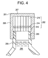
- closure 201 comprising base wall 207 attached to peripheral skirt 208.
- Peripheral skirt 208 is adapted to attach to container 205.
- liner 202 Positioned inside the interior of closure 201 is liner 202.
- Liner 202 may be positioned in the closure by any suitable method such as friction fit or gluing. When liner 202 is glued, first outer layer 210 is typically in direct contact with base wall 207.
- Liner 202 may be any of the liners discussed herein such as those liners and liner materials described in Fig. 2 and Fig. 3.
- Liner 202 comprises first outside layer 210, second outside layer 212 and gas barrier layer 214 positioned between first outside layer 210 and second outside layer 212.
- the second outside layer 212 may be thinner or thicker than first outside layer 210 as long as the gas barrier layer is a LCP, and preferably a wholly aromatic LCP. It is preferred that the LCP gas barrier layer be positioned in the closure such that it is less than about 150 ⁇ m, more preferably less than about 75 ⁇ m from the container to minimize the gas transmission rate. It should also be appreciated that multiple gas barrier layers and multiple outside layers may be used in this invention.
- Base wall 207 and peripheral skirt 208 can be any material typically used in the closure art such as metals, e.g. aluminum, or plastic resins.
- the preferred plastic resins are moldable thermoplastic polymers such as polyethylene, polypropylene, ethylene vinyl acetate, polyethylene terephthalate, polyvinyl chloride and the like.
- adhesive layers may be positioned between the gas barrier layer 214 and outside layers 210 and 212 as described in Fig. 3.
- FIG. 4 illustrates a screw type cap
- any type of closure is contemplated under this application such as twist-off, pilfer proof, crown, lug, tear off, and ring pull.
- the closure of the present invention using the asymmetric liner reduces gas transmission by reducing the vent area.
- the vent area is the thickness of the second outer layer 212 multiplied by the circumference of the liner. Since the vent area is the permeable area of the closure, any reduction in the vent area reduces the gas transmission rate.
- a gas barrier layer resistant to moisture degradation, (e.g., LCP) is preferred in the present invention because the gas barrier layer must be positioned closer to the contents of the container to reduce the vent area.
- moisture sensitive gas barrier layers such as EVOH can be used in the present invention, they are not preferred since their gas barrier properties are reduced under prolong contact with moisture.
- the liners of examples 1 to 3 below were prepared from multilayer plastic sheets produced by conventional sheet co-extrusion technology. Polymers used in the liners were fed to 3 extruders equipped with a multilayer feedblock and single manifold die. The feedbox was used to split and/or direct the different polymers to arrange the flows to form multiple layers. The polymer layers from the feedblock were then directed to an extrusion slot die to spread the layers both parallel and transverse to the flow direction of the polymers to form films. A 3 roll vertical stack was aligned linearly with the extrusion die slot to quench the molten polymer as it was cast. The 760 ⁇ m sheet was then wound in rolls and subsequently die cut to form 38 mm round disks to be used as liners.
- the EVA material used in the liners was an extrusion grade EVA containing about 9% vinyl acetate.
- the barrier layer was either ethylene vinyl alcohol (EVOH) or a wholly aromatic liquid crystal polymer (LCP) containing monomers derived from hydroxybenzoic acid, hydroxynaphthoic acid, terephthalic acid, aminophenol and biphenol.
- the adhesive layer was a terpolymer of ethylene, methyl acrylate and glycidyl methacrylate (E-MA-GMA).
- Liner Examples 4 to 9 were also prepared using a co-extrusion process similar to that described above, with the exception that the liners were made in two steps. First a symmetric 5 layer, thin cast film was prepared, then extrusion laminated to a monolayer EVA sheet.
- the film was made using conventional cast film technology where a melt curtain extruded from a flat, vertically aligned die is drawn onto a single, rotating chrome polished casting roll.
- a draw down ratio (die gap / final sheet thickness) of approximately 4X was used for examples 4 to 7, while a draw down ratio of approximately 10X was used for examples 8 and 9.
- the approximate thickness of the thin film layers (i.e., barrier layer, adhesive layers and thin EVA layer) used in preparing the liners in examples 4 to 9 are shown below in Table 2 and are estimated based on the draw down ratio and the volumetric flow through the film casting extruder.
- the thickness of the thicker EVA layer is the difference between the total 760 ⁇ m liner thickness and the estimated thin film layers thickness.
- Gas transmission rate measurements were conducted on the disk liners in examples 1 to 9 by the following procedure: (1) preparing the closures, (2) conditioning the closures for 1 week at 100% humidity and room temperature, and (3) testing the closures for gas transmission rates.
- Closures were prepared by inserting 760 ⁇ m plastic liners of examples 1 to 9 into approximately 38 mm plastic polypropylene caps. The liners were held in place by a ridge or lip within the cap.
- the closures were applied to "barrier" PET bottles molded for use with a screw-on cap (torque spec: 24 in-Ib.). The bottles were then cut off at 3 mm below the bottle "handling or transfer ring", which is located at approximately 25 mm from the top of the PET bottle.
- the closures were conditioned by introducing small amounts of carbonated water to approximately 28 mm, cylindrical "manifolds", which were used as "special fixtures” for the test.
- the water was required to provide a 100% relative humidity (RH) environment to the inside of the closures.
- the manifolds were essentially small aluminum tubes, closed on one end, positioned vertically and fitted with vacuum grease O-rings to allow for "sealing" to the inside of cut-off PET bottle necks.
- the cut-off top of the bottles with closures attached were then clamped to the manifolds at transfer rings. Clamping directly on the thick, transfer rings was performed to provide a robust clamping area to allow for pressurization and to minimize CO 2 permeability losses through the PET bottles. Pressurization to the inside of the closures was then accomplished by introducing pure, dry CO 2 at 3.0 atmospheres through one of two side ports to the cylindrical manifold. These ports were located below the O-ring.
- the outside atmosphere was maintained at 29°C and 75% RH by placing the manifold in an environmental chamber.
- the closures were then conditioned in this configuration for a minimum of seven (7) days prior to gas transmission rate testing.
- the conditioned closures/bottles on manifolds were then tested for gas transmission rate using a MoCon C-IV carbon dioxide test apparatus.
- the apparatus is a standard CO 2 detection device using infra-red (IR) technology.
- the conditioned closures/bottles on manifolds were first placed under aluminum capture volume containers.
- the aluminum capture volume containers are essentially inverted aluminum cups with two gas flow ports similar to those used for the cylindrical manifolds. These "capture containers” were then sealed to a "base” via vacuum grease and O-rings.
- a nitrogen carrier gas was then introduced into the capture containers, through one of the two ports, at a flow rate of approximately 50-75 cc/min via a mass flow meter.
- the gas flowed through the capture containers until a chart recorder tracing indicated a steady baseline ("zero").
- a chart recorder tracing indicated a steady baseline ("zero").
- the effluent gas stream contained a small, steady stream of nitrogen, as well as some CO 2 permeating from the pressurized closure/bottle a rate to be determined.
- the test instrument was then switched from the purge mode to the accumulation mode.
- the total test time for the accumulation mode was approximately sixty 60 minutes.
- the accumulation mode involved first measuring the IR response to the effluent gas as described above for thirty five minutes, then injecting a standard volumes of CO 2 (0.022 cc at standard pressure and temperature) into the capture container and detector loop.
- the detector response was determined as a difference between the IR detection slopes of the initial gas stream and the gas stream after introduction of the known quantity of CO 2 into the stream. The data were then reduced to a transmission rate.
- a comparison of example 12 with comparative example C-11 shows that a symmetric liner with a thin LCP (18-20 ⁇ m) as the gas barrier layer has a much lower gas transmission rate than a much thicker (50 ⁇ m) EVOH layer.
- These examples demonstrate the superior gas transmission properties of the LCP even at a much thinner thickness than the EVOH.
- a comparison of asymmetrical liner examples 13 to 18 with a LCP thickness of 5-10 ⁇ m demonstrates that the gas transmission rate is reduced when the LCP is positioned closer to the container (i.e., thinner bottom EVA layer).
Landscapes
- Engineering & Computer Science (AREA)
- Mechanical Engineering (AREA)
- Laminated Bodies (AREA)
- Closures For Containers (AREA)
Abstract
Description
- The present invention relates to liners for use in container closures and more particularly to closures with an asymmetric gas barrier liner that reduces the gas transmission rate of food or beverage containers.
- Plastic liners for closures have become widely used and are commercially successful products in the food and beverage packaging industry. Plastic liners are typically a series of polymeric layers containing an outer layer, which provides good slip and torque characteristics to adequately seal and remove the closure from the container, and a gas barrier layer which reduces the transmission of gases. The liner is inserted into the interior of the closure such that the liner contacts the container lip to reduce the transmission of gas into or out of the container. Reduction of gas transmission increases the storage life of food or beverage in the container.
- However, the problem with prior art liners is that they do not adequately retard the transmission of gases, either resulting in a loss of carbon dioxide (from soft drinks) and/or the infusion of oxygen into the container resulting in food spoilage. For example, typical barrier liners use ethylene-vinyl alcohol copolymers (EVOH) as the gas barrier layer. However, EVOH is sensitive to moisture and loses its gas barrier transmission properties when exposed to humidity over a long period of time. In order to remedy this problem, closures containing EVOH liners have either moved the EVOH layer away from the side facing the container and/or have added moisture barrier layers to protect the EVOH gas barrier layer. The problem with adding moisture barrier layers is that it increases the complexity and cost of the closure. Moving the EVOH layer away from the contents of the container enlarges the gas leakage path, illustrated in Fig.1, which results in increased gas transmission rates.
- Fig. 1 is a cross-sectional view of a prior art closure disclosing a
closure 101 withscrew threads 103 andliner 102 situated oncontainer 105.Container 105 contains contents 106 (e.g., a carbonated beverage).Liner 102 comprises a firstoutside layer 110,gas barrier layer 114 and secondoutside layer 112. Secondoutside layer 112 is the layer closest tocontents 106 ofcontainer 105. It is believed that the problem withprior art closure 101 is that there are leakage paths (e.g.,leakage paths 120 and 122) where gas fromcontainer 105 can escape or oxygen fromoutside environment 130 can entercontainer 105. -
Leakage paths container 105 andoutside environment 130. For example, due to cost reasons,closure 101 is typically made from materials that are permeable to gas such as polyethylene or polypropylene which typically exhibit 3-4 orders of magnitude more gas permeability than gas barrier layers. Thus,leakage path 120 illustrates how gas fromcontainer 105 permeates through permeable secondoutside layer 112 ofliner 102 and through the wall ofclosure 101 tooutside environment 130. -
Leakage path 122 illustrates how gas can be transmitted tooutside environment 130 through permeable secondoutside layer 112 andthreads 103. Thus, even ifclosure 101 is made of a high gas barrier layer material, such as aluminum, gas can still leak throughthreads 103 ofclosure 101. - Accordingly,
leakage paths contents 106 incontainer 105 because of high gas transmission rates. - Thus, an object of the present invention is to provide a plastic liner that reduces the gas transmission rate between the container and the outside environment as compared to prior art liners.
- It is another object of the present invention to provide a gas barrier layer, suitable to be used in plastic liners, which is able to retain its gas barrier properties under high humidity conditions.
- It is a further object of the present invention to provide a closure containing a small gas leakage path to reduce the amount of gas transmission between the container and outside environment.
- It is yet another object of the present invention to provide a liner and closure which is simple, inexpensive to manufacture and reliable in operation.
- The objects of the present invention are achieved by providing an asymmetric liner suitable for use in a container closure. The liner comprises a first layer and a second layer where the said second layer is the layer closest to the container. The liner also contains a gas barrier layer between the first and second layer. The thickness of the second layer is less than the thickness of the first layer to reduce the gas leakage path between the container and the outside environment.
- In another embodiment of the present invention, a closure for a container is provided such that the closure comprises a base wall and a peripheral skirt. The skirt is affixed to the base wall defining a closure interior and is adapted to attach to the container. A liner is positioned inside the closure interior. The liner comprises a first layer, a second layer, and a gas barrier layer between the first and second layer where the gas barrier layer is a liquid crystal polymer (LCP).
- Reference now is made to the accompanying drawings of illustrative embodiments of the invention in which:
- FIG. 1 is a cross-sectional view of a prior art closure illustrating gas leakage paths between the container and the closure.
- FIG. 2 is a cross sectional view of one embodiment of the liner according to the present invention;
- FIG. 3 is a cross sectional view of another embodiment of the liner according to the present invention; and
- FIG. 4 is cross sectional view of one embodiment of the closure according to the present invention.
-
- The present invention relates to an asymmetric liner designed to reduce the gas transmission rate between the contents of a container and the outside environment. Reducing the gas leakage path between the closure and the outside environment reduces the gas transmission rate. In this application, asymmetrical means that the gas barrier layer is not situated at the midpoint of the liner.
- The asymmetric liner comprises a first layer and a second layer where the second layer is the layer closest to the container. The liner also contains a gas barrier layer between the first and second layer. The thickness of the second layer is less than the thickness of the first layer to reduce the gas leakage path.
- FIG. 2 is a cross sectional view of one embodiment of the liner according to the present invention.
Liner 202 comprises firstoutside layer 210, secondoutside layer 212 andgas barrier layer 214 positioned between firstoutside layer 210 and secondoutside layer 212. Second outsidelayer 212 is the layer closest to the container and is thinner than firstoutside layer 210. - Generally, the total thickness of
liner 202 is between about 500 to about 2000 microns (µm). Preferably, the thickness of firstoutside layer 210 is about 375 to about 1250 µm and more preferably about 625 to about 875 µm. The thickness of secondoutside layer 212 is generally less than about 250 µm, preferably less than about 150 µm, more preferably less than about 75 µm and even more preferably ranges between about 25 µm to about 75 µm or about 40 µm to about 60 µm. - The thickness of
gas barrier layer 214 is typically less than about 50 µm, preferably less than about 25 µm, and more preferably ranges between about 2 µm to about 15 µm, and about 5 µm to about 10 µm. The exact thickness ofgas barrier layer 214 is a trade-off between gas transmission rate and cost. A thicker gas barrier layer reduces gas transmission rates, but increases cost. - In addition, it should be noted that multiple gas barrier layers may also be used in this invention. The multiple gas barrier layers may be positioned between the same materials that are used to make the outer layers, or positioned between other gas barrier layer materials.
- The gas barrier layer is preferably prepared from materials that provide a barrier to gas transmission and are insensitive to moisture since the gas barrier layer is positioned close to the contents of the container. EVOH may be used as a gas barrier layer, but is not preferred in the present invention because EVOH is sensitive to moisture and loses its gas barrier properties when exposed to humidity over a long period of time.
- Thus, preferred materials to be used for the gas barrier layer are those resistant to moisture degradation. Resistant to moisture degradation means that the gas barrier properties are not substantially reduced by exposure to moisture. Examples of moisture resistant gas barrier layers include, but are not limited to Liquid Crystal Polymers (LCPs) and polyvinylidene chloride. More preferably, the gas barrier layer is made of a LCP and even more preferably a wholly aromatic LCP.
- Liquid crystalline polymers (LCPs) are characterized as having a liquid crystalline phase above the temperature at which the polymers become molten. They have good gas barrier properties and are able to withstand high humidity environments. The LCPs used in the liners described herein are generally polyesters or poly(ester-amides), and generally comprise monomer units that include within their structures, exclusive of functional groups, one or more of the following aromatic nuclei: 1,4-phenylene, 1,3-phenylene, 4,4'-biphenylene, and 2,6- and/or 2,7-naphthylene. Some LCPs also contain monomer units that are derived from ethylene glycol. LCPs that may be used in this invention include the polymers that are available from Ticona and sold under the VECTRA trademark, LCPs available from BP-Amoco Chemicals and sold under the XYDAR trademark, and LCPs available from DuPont and sold under the ZENITE trademark.
- Generally, the LCP's comprising wholly aromatic monomer units can be derived from one or more of the following monomers and generally at least two of the following monomers: terephthalic acid, isophthalic acid, 1,4-hydroquinone, resorcinol, 4-aminobenzoic acid, 3-aminobenzoic acid, 4-hydroxybenzoic acid, 3-hydroxybenzoic acid, 4-aminophenol, 3-aminophenol, 1,4-phenylenediamine, 4,4'-biphenol, 4,4'-biphenyldicarboxylic acid, 6-hydroxy-2-naphthoic acid, 2,6-naphthalenedicarboxylic acid, and 2,6-dihydroxynaphthalene.
- Additional examples of gas barrier layer materials that may be used in this invention are blends of LCP with thermoplastics, preferably polyolefins or other gas barrier layer materials. Examples of polyolefins that may be blended with LCP include, but are not limited to polyethylene, polypropylene, ethylene-propylene copolymers, ethylene vinyl acetate (EVA), ethylene methyl acrylate, styrene-ethylene copolymers, EVOH, and the like. Preferred polyolefins that may be blended with LCP are polyethylene, polypropylene, polyvinylidene chloride, EVA, EVOH and mixtures thereof. Gas barrier layer materials that may be blended with LCP are polyvinylidene chloride, EVOH, polyethylene terephthalate, polyethylene naphthalate, cyclic olefin copolymers, polyamides such as MXD6 (a copolyamide of meta-xylyenediamine and adipic acid produced by Mitsubishi Gas Chemical), polyacrylonitrile and mixtures thereof. The amount of LCP in the LCP blend may range from about 0.1 to about 99 wt.% based on the total weight of the blend.
- It is preferred that a compatibilizer be used in the LCP blends. The task of a compatibilizer is to better achieve a more uniform dispersed blend such as by diminishing the surface tension and/or improving adhesion between the components. Any suitable compatibilizer may be used to achieve a uniform dispersed blend such as those described in WO 96/00752 and WO 93/24574, herein incorporated by reference. A preferred compatibilizer for use in the LCP blends is a functionalized polyolefin, where the functional groups included, but are not limited to a carboxyl group and its esters, a carboxylic anhydride group, a glycidyl group, an alkoxysilane group and combinations thereof. The amount of the compatibilizer may range from about 0.1 to about 30 wt.% based on the total weight of the LCP and the thermoplastic.
- First outside
layer 210 and secondoutside layer 212 can be made from the same or different materials such as thermoplastic elastomers, polyolefins and combinations thereof. A thermoplastic elastomer is a polymer having the processability of a thermoplastic material and the functional performance and properties of a thermoset rubber. Examples of thermoplastic elastomers include, but are not limited to, styrene block copolymers, elastomeric alloys, thermoplastic polyurethane, thermoplastic polyesters and thermoplastic polyamides. Polyolefins may also be considered thermoplastic elastomers. Thermoplastic elastomers are described starting on page 93 in Modern Plastics Handbook, published by McGraw-Hill, 1988. - The polyolefins used in the present invention for the first or second outer layer can be homopolymers, or copolymers comprising more than one monomer repeating unit. Examples of polyolefins that may be used include, but are not limited to, polyethylene, polypropylene, ethylene-propylene copolymers, ethylene vinyl acetate, ethylene methyl acrylate, styrene-ethylene copolymers and the like. Preferred polyolefins are polyethylene, polypropylene, and ethylene vinyl acetate.
- Fig. 3 is another liner embodiment of the present invention providing an adhesive layer between the first or second outer layer, and inner gas barrier layer.
Liner 202 in Fig. 3 comprises firstoutside layer 210, secondoutside layer 212,gas barrier layer 214 and at least oneadhesive layers 216 and/or 218 positioned betweenoutside layers 210 and/or 212 andgas barrier layer 214. Again secondoutside layer 212 is the layer closest to the container and is thinner thanfirst barrier layer 210. The same materials described above may be used foroutside layers gas barrier layer 214. - An adhesive is any substance that is capable of binding other substances together by surface attachment such as by a reactive bond (covalent or dipole-dipole) or a non-reactive means (chain entanglement with polymers). Any suitable adhesive may be used to bind
outer layer gas barrier layer 214. In the case when the gas barrier layer is a LCP, it is preferred that the adhesive layer is a functionalized polyolefin. Examples of suitable functional groups for the functionalized polyolefins include, but are not limited to, a carboxyl group and its esters, a carboxylic anhydride group, a glycidyl group, an alkoxysilane group and combinations thereof. A preferred adhesive layer is a terpolymer of ethylene, methyl acrylate and glycidyl methacrylate. Such adhesives for LCPs are disclosed in U.S. Patent Nos. 6,015,524 and 6,013,373, herein incorporated by reference. - The liner of the present invention may be made by any suitable method such as co-extrusion of the layers or forming films of the different layers separately and laminating them together. The multilayer film can then be "punched out" forming the liner. In a preferred method, the gas barrier layer is made up of a wholly aromatic LCP and is co-extruded with polyolefin outside layers.
- Referring to Fig. 4, another embodiment of the present invention is
closure 201 comprisingbase wall 207 attached toperipheral skirt 208.Peripheral skirt 208 is adapted to attach tocontainer 205. Positioned inside the interior ofclosure 201 isliner 202.Liner 202 may be positioned in the closure by any suitable method such as friction fit or gluing. Whenliner 202 is glued, firstouter layer 210 is typically in direct contact withbase wall 207.Liner 202 may be any of the liners discussed herein such as those liners and liner materials described in Fig. 2 and Fig. 3.Liner 202 comprises firstoutside layer 210, secondoutside layer 212 andgas barrier layer 214 positioned between firstoutside layer 210 and secondoutside layer 212.Liner 202 in Fig. 4 may be symmetrical or the secondoutside layer 212 may be thinner or thicker than firstoutside layer 210 as long as the gas barrier layer is a LCP, and preferably a wholly aromatic LCP. It is preferred that the LCP gas barrier layer be positioned in the closure such that it is less than about 150 µm, more preferably less than about 75 µm from the container to minimize the gas transmission rate. It should also be appreciated that multiple gas barrier layers and multiple outside layers may be used in this invention. -
Base wall 207 andperipheral skirt 208 can be any material typically used in the closure art such as metals, e.g. aluminum, or plastic resins. The preferred plastic resins are moldable thermoplastic polymers such as polyethylene, polypropylene, ethylene vinyl acetate, polyethylene terephthalate, polyvinyl chloride and the like. - In addition, adhesive layers may be positioned between the
gas barrier layer 214 andoutside layers - It should be appreciated that all Figures in this application may not be drawn to scale and thicknesses may be exaggerated for illustration purposes. It should also be appreciated that although Fig. 4 illustrates a screw type cap, any type of closure is contemplated under this application such as twist-off, pilfer proof, crown, lug, tear off, and ring pull.
- Although not wishing to be bound by any theory, it is believed that the closure of the present invention using the asymmetric liner reduces gas transmission by reducing the vent area. The vent area is the thickness of the second
outer layer 212 multiplied by the circumference of the liner. Since the vent area is the permeable area of the closure, any reduction in the vent area reduces the gas transmission rate. A gas barrier layer resistant to moisture degradation, (e.g., LCP) is preferred in the present invention because the gas barrier layer must be positioned closer to the contents of the container to reduce the vent area. Although moisture sensitive gas barrier layers such as EVOH can be used in the present invention, they are not preferred since their gas barrier properties are reduced under prolong contact with moisture. - Many features of the present invention will become apparent in the course of the following description of the exemplary embodiments, which are given for illustration of the invention and are not intended to be limiting thereof.
- The liners of examples 1 to 3 below were prepared from multilayer plastic sheets produced by conventional sheet co-extrusion technology. Polymers used in the liners were fed to 3 extruders equipped with a multilayer feedblock and single manifold die. The feedbox was used to split and/or direct the different polymers to arrange the flows to form multiple layers. The polymer layers from the feedblock were then directed to an extrusion slot die to spread the layers both parallel and transverse to the flow direction of the polymers to form films. A 3 roll vertical stack was aligned linearly with the extrusion die slot to quench the molten polymer as it was cast. The 760µm sheet was then wound in rolls and subsequently die cut to form 38 mm round disks to be used as liners.
- The EVA material used in the liners was an extrusion grade EVA containing about 9% vinyl acetate. The barrier layer was either ethylene vinyl alcohol (EVOH) or a wholly aromatic liquid crystal polymer (LCP) containing monomers derived from hydroxybenzoic acid, hydroxynaphthoic acid, terephthalic acid, aminophenol and biphenol. The adhesive layer was a terpolymer of ethylene, methyl acrylate and glycidyl methacrylate (E-MA-GMA).
- The approximate thickness of the layers in examples 1 to 3 are shown in Table 1 below and were estimated based on the volumetric flow through the extruder.
Example TOP EVA Thickness (µm) Adhesive Thickness (µm) Barrier Layer Thickness (µm) Adhesive Thickness (µm) Bottom EVA Thickness (µm) C-1 380 0 0 0 380 C-2 330 25 50 (EVOH) 25 330 C-3 360 5-10 18-20 (LCP) 5-10 360 - Liner Examples 4 to 9 were also prepared using a co-extrusion process similar to that described above, with the exception that the liners were made in two steps. First a symmetric 5 layer, thin cast film was prepared, then extrusion laminated to a monolayer EVA sheet.
- The film was made using conventional cast film technology where a melt curtain extruded from a flat, vertically aligned die is drawn onto a single, rotating chrome polished casting roll. A draw down ratio (die gap / final sheet thickness) of approximately 4X was used for examples 4 to 7, while a draw down ratio of approximately 10X was used for examples 8 and 9.
- These films were then extrusion laminated to an EVA sheet to form approximately 760 µm thick liners. This was accomplished by mounting rolls of the films to a tension controlled "unwind" station, and feeding the film between the first and second rolls of a 3 roll stack used in conventional sheet extrusion technology. A molten sheet of EVA film was also fed between the second and third roll and adhesion of the film to the single layer EVA sheet was . accomplished by "melting" the film to the molten EVA polymer where they meet between the rolls. The final sheet was cooled on the roll stack, then taken up on a winder for subsequent use. As with examples 1 to 3 described above, the laminated sheet was then die cut into 38-mm disks for use as liners.
- The approximate thickness of the thin film layers (i.e., barrier layer, adhesive layers and thin EVA layer) used in preparing the liners in examples 4 to 9 are shown below in Table 2 and are estimated based on the draw down ratio and the volumetric flow through the film casting extruder. The thickness of the thicker EVA layer is the difference between the total 760 µm liner thickness and the estimated thin film layers thickness.
Example TOP EVA Thickness (µm) Adhesive Thickness (µm)** Barrier Layer Thickness (µm)** Adhesive Thickness (µm)** Bottom EVA Thickness (µm) 4 700 5 5-10 (LCP) 5 50 5 50 5 5-10 (LCP) 5 700 6 700 5 5-10 (LCP) 5 50 7 50 5 5-10 (LCP) 5 700 8 725 5 5-10 (LCP) 5 25 9 25 5 5-10 (LCP) 5 725 - Gas transmission rate measurements were conducted on the disk liners in examples 1 to 9 by the following procedure: (1) preparing the closures, (2) conditioning the closures for 1 week at 100% humidity and room temperature, and (3) testing the closures for gas transmission rates. Closures were prepared by inserting 760 µm plastic liners of examples 1 to 9 into approximately 38 mm plastic polypropylene caps. The liners were held in place by a ridge or lip within the cap. The closures were applied to "barrier" PET bottles molded for use with a screw-on cap (torque spec: 24 in-Ib.). The bottles were then cut off at 3 mm below the bottle "handling or transfer ring", which is located at approximately 25 mm from the top of the PET bottle.
- The closures were conditioned by introducing small amounts of carbonated water to approximately 28 mm, cylindrical "manifolds", which were used as "special fixtures" for the test. The water was required to provide a 100% relative humidity (RH) environment to the inside of the closures. The manifolds were essentially small aluminum tubes, closed on one end, positioned vertically and fitted with vacuum grease O-rings to allow for "sealing" to the inside of cut-off PET bottle necks. The cut-off top of the bottles with closures attached were then clamped to the manifolds at transfer rings. Clamping directly on the thick, transfer rings was performed to provide a robust clamping area to allow for pressurization and to minimize CO2 permeability losses through the PET bottles. Pressurization to the inside of the closures was then accomplished by introducing pure, dry CO2 at 3.0 atmospheres through one of two side ports to the cylindrical manifold. These ports were located below the O-ring.
- The outside atmosphere was maintained at 29°C and 75% RH by placing the manifold in an environmental chamber. The closures were then conditioned in this configuration for a minimum of seven (7) days prior to gas transmission rate testing.
- The conditioned closures/bottles on manifolds were then tested for gas transmission rate using a MoCon C-IV carbon dioxide test apparatus. The apparatus is a standard CO2 detection device using infra-red (IR) technology. The conditioned closures/bottles on manifolds were first placed under aluminum capture volume containers. The aluminum capture volume containers are essentially inverted aluminum cups with two gas flow ports similar to those used for the cylindrical manifolds. These "capture containers" were then sealed to a "base" via vacuum grease and O-rings. A nitrogen carrier gas was then introduced into the capture containers, through one of the two ports, at a flow rate of approximately 50-75 cc/min via a mass flow meter. The gas flowed around the closure/bottle manifolds and exited from the other port to the IR detector. The gas flowed through the capture containers until a chart recorder tracing indicated a steady baseline ("zero"). During that purge time, the effluent gas stream contained a small, steady stream of nitrogen, as well as some CO2 permeating from the pressurized closure/bottle a rate to be determined.
- The test instrument was then switched from the purge mode to the accumulation mode. The total test time for the accumulation mode was approximately sixty 60 minutes. The accumulation mode involved first measuring the IR response to the effluent gas as described above for thirty five minutes, then injecting a standard volumes of CO2 (0.022 cc at standard pressure and temperature) into the capture container and detector loop. The detector response was determined as a difference between the IR detection slopes of the initial gas stream and the gas stream after introduction of the known quantity of CO2 into the stream. The data were then reduced to a transmission rate.
- The gas transmission rates for the liners in examples 1 to 9 are shown in Table 3 below.
Example Liner Example No. Bottom Layer Thickness (µm) CO2 loss (cc/day-atm) C-10 C-1 (No Barrier Layer) N/A 1.39 C-11 C-2 (EVOH) 330 0.32 12 3 (LCP) 350 0.09 13 4 (LCP) 700 0.17 14 5 (LCP) 50 0.12 15 6 (LCP) 700 0.54 16 7 (LCP) 50 0.09 17 8 (LCP) 725 0.21 18 9 (LCP) 25 0.11 - A comparison of example 12 with comparative example C-11 shows that a symmetric liner with a thin LCP (18-20 µm) as the gas barrier layer has a much lower gas transmission rate than a much thicker (50 µm) EVOH layer. These examples demonstrate the superior gas transmission properties of the LCP even at a much thinner thickness than the EVOH.
- A comparison of asymmetrical liner examples 13 to 18 with a LCP thickness of 5-10 µm demonstrates that the gas transmission rate is reduced when the LCP is positioned closer to the container (i.e., thinner bottom EVA layer).
- The foregoing is illustrative of the present invention and is not construed as limiting thereof. The invention is defined by the following claims with equivalents of the claims to be included therein.
Claims (40)
- An asymmetric liner suitable for use in a container closure comprising:wherein the thickness of said second layer is less than the thickness of said first layer.a first layer;a second layer wherein said second layer is positioned closer to a container than said first layer; anda gas barrier layer between said first layer and said second layer;
- The liner of claim 1 wherein said gas barrier layer is resistant to moisture degradation.
- The liner of claim 2 wherein said gas barrier layer is selected from the group consisting of: liquid crystal polymer (LCP) and polyvinylidene chloride.
- The liner of claim 2 wherein said gas barrier layer is a LCP.
- The liner of claim 4 wherein said LCP is a wholly aromatic LCP.
- The liner of claim 5 wherein said LCP is derived from at least one monomer selected from the group consisting of: terephthalic acid, isophthalic acid, 1,4-hydroquinone, resorcinol, 4-aminobenzoic acid, 3-aminobenzoic acid, 4-hydroxybenzoic acid, 3-hydroxybenzoic acid, 4-aminophenol, 3-aminophenol, 1,4-phenylenediamine, 4,4'-biphenol, 4,4'-biphenyldicarboxylic acid, 6-hydroxy-2-naphthoic acid, 2,6-naphthalenedicarboxylic acid, and 2,6-dihydroxynaphthalene.
- The liner of claim 4 wherein said first layer and said second layer can be the same or different and selected from the group consisting of: thermoplastic elastomer, polyolefin and combinations thereof.
- The liner of claim 7 wherein said first or second layer is a polyolefin.
- The liner of claim 8 wherein said polyolefin is selected from the group consisting of: polyethylene, polypropylene, and ethylene vinyl acetate.
- The liner of claim 4 further comprising an adhesive layer between said gas barrier layer and said first or second layer.
- The liner of claim 10 wherein said adhesive layer is comprised of a functionalized polyolefin material.
- The liner of claim 11 wherein said functionalized polyolefin material comprises at least one functional group selected from the group consisting of: a carboxyl group or its esters, a carboxylic anhydride group, a glycidyl group and an alkoxysilane group.
- The liner of claim 11 wherein said functionalized polyolefin material is a terpolymer of ethylene, methyl acrylate and glycidyl methacrylate.
- The liner of claim 4 wherein the thickness of said first layer is about 375 µm to about 1250 µm and the thickness of said second layer is less than about 150 µm.
- The liner of claim 4 wherein the thickness of said first layer is about 625 µm to about 875 µm and the thickness of said second layer is less than about 75 µm.
- The liner of claim 15 wherein the thickness of said barrier layer is between about 2 to about 15 µm.
- The liner of claim 16 wherein said first and said second layer is ethylene vinyl acetate.
- A closure for a container comprising:a base wall;a peripheral skirt affixed to said base wall defining a closure interior, wherein said skirt is adapted to attach to said container; anda liner positioned inside said closure interior, said liner comprising:a first layer;a second layer; anda gas barrier layer between said first layer and said second layer;wherein said gas barrier layer is a liquid crystal polymer (LCP).
- The closure of claim 18 wherein said liner is asymmetric and wherein said LCP is a wholly aromatic LCP.
- The closure of claim 18 wherein said gas barrier layer is a blend of a LCP with a thermoplastic.
- The closure of claim 20 wherein said thermoplastic is a polyolefin selected from the group consisting of: polyethylene, polypropylene, polyvinylidene chloride, EVA, and mixtures thereof.
- The closure of claim 20 wherein said thermoplastic is a gas barrier layer selected from the group consisting of: polyvinylidene chloride, EVOH, polyethylene terephthalate, polyethylene naphthalate, cyclic olefin copolymers, polyamides, polyacrylonitrile and mixtures thereof.
- The closure of claim 20 wherein said blend further comprises a compatibilizer.
- The closure of claim 19 wherein said second layer is the layer closest to said container and wherein the thickness of said second layer is less than the thickness of said first layer.
- The closure of claim 18 wherein said second layer is positioned to contact said container.
- The closure of claim 24 wherein said first layer is attached to said base wall.
- The closure of claim 24 wherein said LCP is derived from at least one monomer selected from the group consisting of: terephthalic acid, isophthalic acid, 1,4-hydroquinone, resorcinol, 4-aminobenzoic acid, 3-aminobenzoic acid, 4-hydroxybenzoic acid, 3-hydroxybenzoic acid, 4-aminophenol, 3-aminophenol, 1,4-phenylenediamine, 4,4'-biphenol, 4,4'-biphenyldicarboxylic acid, 6-hydroxy-2-naphthoic acid, 2,6-naphthalenedicarboxylic acid, and 2,6-dihydroxynaphthalene.
- The closure of claim 27 wherein said first or second layer is a polyolefin.
- The closure of claim 28 wherein said polyolefin is selected from the group consisting of: polyethylene, polypropylene, and ethylene vinyl acetate.
- The closure of claim 18 further comprising an adhesive layer between said gas barrier layer and said first or second layer.
- The closure of claim 30 wherein said adhesive layer is comprised of a functionalized polyolefin material.
- The closure of claim 31 wherein said functionalized polyolefin material comprises at least one functional group selected from the group consisting of a carboxyl group or its esters, a carboxylic anhydride group, a glycidyl group and an alkoxysilane group.
- The closure of claim 28 wherein said functionalized polyolefin material is a terpolymer of ethylene, methyl acrylate and glycidyl methacrylate.
- The closure of claim 24 wherein the thickness of said first layer is about 375 µm to about 1250 µm and the thickness of said second layer is less than about 150 µm.
- The closure of claim 24 wherein the thickness of said first layer is about 625 µm to about 875 µm and the thickness of said second layer is less than about 75 µm.
- The closure of claim 35 wherein the thickness of said barrier layer is between about 2 to about 15 µm.
- The closure of claim 36 wherein said first and said second layer is ethylene vinyl acetate.
- The closure of claim 18 wherein said gas barrier layer is less than about 150 µm from said container.
- The closure of claim 18 wherein said gas barrier layer is less than about 75 µm from said container.
- The closure of claim 18 wherein said closure is selected from the group consisting of: screw, twist-off, pilfer proof, crown, lug, tear off, and ring pull.
Applications Claiming Priority (2)
| Application Number | Priority Date | Filing Date | Title |
|---|---|---|---|
| US625107 | 1984-06-27 | ||
| US62510700A | 2000-07-25 | 2000-07-25 |
Publications (2)
| Publication Number | Publication Date |
|---|---|
| EP1176102A2 true EP1176102A2 (en) | 2002-01-30 |
| EP1176102A3 EP1176102A3 (en) | 2002-05-29 |
Family
ID=24504611
Family Applications (1)
| Application Number | Title | Priority Date | Filing Date |
|---|---|---|---|
| EP01306087A Withdrawn EP1176102A3 (en) | 2000-07-25 | 2001-07-16 | High gas barrier asymmetric liner and closure |
Country Status (2)
| Country | Link |
|---|---|
| EP (1) | EP1176102A3 (en) |
| JP (1) | JP2002114260A (en) |
Citations (4)
| Publication number | Priority date | Publication date | Assignee | Title |
|---|---|---|---|---|
| WO1993024574A1 (en) | 1992-05-29 | 1993-12-09 | Neste Oy | Liquid crystal polymer blends, process for the preparation thereof and products manufactured from the blends |
| WO1996000752A1 (en) | 1994-06-28 | 1996-01-11 | Foster-Miller, Inc. | Compatibilized lcp blends |
| US6013373A (en) | 1997-10-20 | 2000-01-11 | Hoechst Celanese Corporation | Adhesives for making multilayer films comprising liquid crystalline polymer and polypropylene |
| US6015524A (en) | 1997-10-20 | 2000-01-18 | Hoechst Celanese Corporation | Adhesives for making multilayer films comprising liquid crystalline polymers and polyethylene |
Family Cites Families (7)
| Publication number | Priority date | Publication date | Assignee | Title |
|---|---|---|---|---|
| JPS54148687A (en) * | 1978-05-11 | 1979-11-21 | Crown Cork Japan | Container lid |
| JPS5926460A (en) * | 1982-08-06 | 1984-02-10 | 東洋製罐株式会社 | Composite material for packing vessel cover |
| US4774134A (en) * | 1987-03-13 | 1988-09-27 | Continental White Cap, Inc. | Low oxygen barrier type plastic closure with an adhered gasketing compound and method of forming same |
| DE69022214T2 (en) * | 1989-10-04 | 1996-02-22 | Toyo Seikan Kaisha Ltd | CONTAINER WITH HEAT SEAL FOR STORING ITEMS UNDER AIR. |
| US6139931A (en) * | 1997-07-10 | 2000-10-31 | Tri-Seal Holdings, Inc. | High barrier closure liner for carbonated beverage containers and the like |
| US6194042B1 (en) * | 1997-07-10 | 2001-02-27 | Tri-Seal Holdings, Inc. | High barrier closure liner with oxygen absorbing capabilities |
| JP2000344269A (en) * | 1999-03-30 | 2000-12-12 | Nihon Yamamura Glass Co Ltd | Membrane for cap and cap having the membrane mounted therein |
-
2001
- 2001-07-16 EP EP01306087A patent/EP1176102A3/en not_active Withdrawn
- 2001-07-25 JP JP2001224292A patent/JP2002114260A/en active Pending
Patent Citations (4)
| Publication number | Priority date | Publication date | Assignee | Title |
|---|---|---|---|---|
| WO1993024574A1 (en) | 1992-05-29 | 1993-12-09 | Neste Oy | Liquid crystal polymer blends, process for the preparation thereof and products manufactured from the blends |
| WO1996000752A1 (en) | 1994-06-28 | 1996-01-11 | Foster-Miller, Inc. | Compatibilized lcp blends |
| US6013373A (en) | 1997-10-20 | 2000-01-11 | Hoechst Celanese Corporation | Adhesives for making multilayer films comprising liquid crystalline polymer and polypropylene |
| US6015524A (en) | 1997-10-20 | 2000-01-18 | Hoechst Celanese Corporation | Adhesives for making multilayer films comprising liquid crystalline polymers and polyethylene |
Also Published As
| Publication number | Publication date |
|---|---|
| JP2002114260A (en) | 2002-04-16 |
| EP1176102A3 (en) | 2002-05-29 |
Similar Documents
| Publication | Publication Date | Title |
|---|---|---|
| CA1037370A (en) | Packaging of foodstuffs | |
| CA2295299C (en) | High barrier closure liner with oxygen absorbing capabilities | |
| US4919984A (en) | Multilayer plastic container | |
| CA2318846C (en) | High barrier closure liner for carbonated beverage containers and the like | |
| EP0298762A2 (en) | Cap liner | |
| EP0179639A2 (en) | Multilayer plastic articles | |
| US4729926A (en) | Packaging material for long-term storage of shelf stable food products and method of making same | |
| MXPA01012629A (en) | Barrier material made of extruded microlayers. | |
| US3759379A (en) | Flexible halogen package | |
| MXPA05004457A (en) | Container closure with a multi-layer oxygen barrier liner. | |
| NZ229867A (en) | Multilayer structure comprising at least two good gas barrier layers and at least one relatively permeable layer, the former comprising polymer containing glutarimide units | |
| TWI915391B (en) | Laminated sheets and packaging | |
| US5250334A (en) | Coffee web | |
| JP2002114260A (en) | Unsymmetrical liner with high gas cutoff properties and closure | |
| Jabarin et al. | Polyolefin properties for rigid food packaging | |
| EP3645276A2 (en) | Pouch and film for a pouch | |
| US4971847A (en) | Multilayered structures | |
| JPH09226070A (en) | Gas barrier laminated film | |
| CA1311593C (en) | Packaging material for long-term storage of shelf stable food products | |
| EP4461534A1 (en) | Packaging bag laminate, packaging bag, spouted packaging bag, and content-filled spouted packaging bag | |
| JP3937452B2 (en) | Anethole beverage package | |
| JPH08332704A (en) | Easy tear laminate film and easy tear bag | |
| JP3367290B2 (en) | Easy tearing laminate film and easy tearing bag | |
| EP0919365B1 (en) | Composite sheet and sealed container | |
| US7981492B2 (en) | Film structures and packages therefrom useful for respiring food products that release CO2 amounts |
Legal Events
| Date | Code | Title | Description |
|---|---|---|---|
| PUAI | Public reference made under article 153(3) epc to a published international application that has entered the european phase |
Free format text: ORIGINAL CODE: 0009012 |
|
| AK | Designated contracting states |
Kind code of ref document: A2 Designated state(s): AT BE CH CY DE DK ES FI FR GB GR IE IT LI LU MC NL PT SE TR |
|
| AX | Request for extension of the european patent |
Free format text: AL;LT;LV;MK;RO;SI |
|
| PUAL | Search report despatched |
Free format text: ORIGINAL CODE: 0009013 |
|
| RIC1 | Information provided on ipc code assigned before grant |
Free format text: 7B 65D 41/04 A, 7B 32B 27/00 B |
|
| AK | Designated contracting states |
Kind code of ref document: A3 Designated state(s): AT BE CH CY DE DK ES FI FR GB GR IE IT LI LU MC NL PT SE TR |
|
| AX | Request for extension of the european patent |
Free format text: AL;LT;LV;MK;RO;SI |
|
| STAA | Information on the status of an ep patent application or granted ep patent |
Free format text: STATUS: THE APPLICATION HAS BEEN WITHDRAWN |
|
| 17P | Request for examination filed |
Effective date: 20020917 |
|
| 18W | Application withdrawn |
Withdrawal date: 20021001 |