EP1175961A2 - Method and apparatus for machining workpiece surfaces - Google Patents
Method and apparatus for machining workpiece surfaces Download PDFInfo
- Publication number
- EP1175961A2 EP1175961A2 EP01117029A EP01117029A EP1175961A2 EP 1175961 A2 EP1175961 A2 EP 1175961A2 EP 01117029 A EP01117029 A EP 01117029A EP 01117029 A EP01117029 A EP 01117029A EP 1175961 A2 EP1175961 A2 EP 1175961A2
- Authority
- EP
- European Patent Office
- Prior art keywords
- tools
- tool
- machining
- frame
- tool unit
- Prior art date
- Legal status (The legal status is an assumption and is not a legal conclusion. Google has not performed a legal analysis and makes no representation as to the accuracy of the status listed.)
- Withdrawn
Links
- 238000003754 machining Methods 0.000 title claims abstract description 43
- 238000000034 method Methods 0.000 title claims description 20
- 238000012545 processing Methods 0.000 claims description 98
- 235000013358 Solanum torvum Nutrition 0.000 claims description 34
- 240000002072 Solanum torvum Species 0.000 claims description 34
- 238000003860 storage Methods 0.000 claims description 31
- 230000033001 locomotion Effects 0.000 claims description 17
- 230000002093 peripheral effect Effects 0.000 claims description 5
- 230000005540 biological transmission Effects 0.000 claims description 4
- 238000009434 installation Methods 0.000 claims description 4
- 230000010355 oscillation Effects 0.000 claims description 4
- 238000009966 trimming Methods 0.000 claims description 4
- 230000002441 reversible effect Effects 0.000 claims description 3
- 239000000463 material Substances 0.000 description 10
- 230000006978 adaptation Effects 0.000 description 2
- 238000013461 design Methods 0.000 description 2
- 238000000227 grinding Methods 0.000 description 2
- 239000002184 metal Substances 0.000 description 2
- 239000004033 plastic Substances 0.000 description 2
- 229920003023 plastic Polymers 0.000 description 2
- 239000002023 wood Substances 0.000 description 2
- 241001136792 Alle Species 0.000 description 1
- 241000256251 Spodoptera frugiperda Species 0.000 description 1
- 230000009286 beneficial effect Effects 0.000 description 1
- 238000004140 cleaning Methods 0.000 description 1
- 230000001419 dependent effect Effects 0.000 description 1
- 238000011161 development Methods 0.000 description 1
- 230000018109 developmental process Effects 0.000 description 1
- 230000003534 oscillatory effect Effects 0.000 description 1
- 238000005498 polishing Methods 0.000 description 1
- 238000005096 rolling process Methods 0.000 description 1
- 238000004381 surface treatment Methods 0.000 description 1
- 238000012549 training Methods 0.000 description 1
Images

Classifications
-
- B—PERFORMING OPERATIONS; TRANSPORTING
- B24—GRINDING; POLISHING
- B24B—MACHINES, DEVICES, OR PROCESSES FOR GRINDING OR POLISHING; DRESSING OR CONDITIONING OF ABRADING SURFACES; FEEDING OF GRINDING, POLISHING, OR LAPPING AGENTS
- B24B29/00—Machines or devices for polishing surfaces on work by means of tools made of soft or flexible material with or without the application of solid or liquid polishing agents
- B24B29/005—Machines or devices for polishing surfaces on work by means of tools made of soft or flexible material with or without the application of solid or liquid polishing agents using brushes
-
- B—PERFORMING OPERATIONS; TRANSPORTING
- B24—GRINDING; POLISHING
- B24B—MACHINES, DEVICES, OR PROCESSES FOR GRINDING OR POLISHING; DRESSING OR CONDITIONING OF ABRADING SURFACES; FEEDING OF GRINDING, POLISHING, OR LAPPING AGENTS
- B24B41/00—Component parts such as frames, beds, carriages, headstocks
- B24B41/04—Headstocks; Working-spindles; Features relating thereto
- B24B41/047—Grinding heads for working on plane surfaces
-
- B—PERFORMING OPERATIONS; TRANSPORTING
- B24—GRINDING; POLISHING
- B24B—MACHINES, DEVICES, OR PROCESSES FOR GRINDING OR POLISHING; DRESSING OR CONDITIONING OF ABRADING SURFACES; FEEDING OF GRINDING, POLISHING, OR LAPPING AGENTS
- B24B7/00—Machines or devices designed for grinding plane surfaces on work, including polishing plane glass surfaces; Accessories therefor
- B24B7/06—Machines or devices designed for grinding plane surfaces on work, including polishing plane glass surfaces; Accessories therefor involving conveyor belts, a sequence of travelling work-tables or the like
-
- B—PERFORMING OPERATIONS; TRANSPORTING
- B24—GRINDING; POLISHING
- B24D—TOOLS FOR GRINDING, BUFFING OR SHARPENING
- B24D13/00—Wheels having flexibly-acting working parts, e.g. buffing wheels; Mountings therefor
- B24D13/02—Wheels having flexibly-acting working parts, e.g. buffing wheels; Mountings therefor acting by their periphery
- B24D13/10—Wheels having flexibly-acting working parts, e.g. buffing wheels; Mountings therefor acting by their periphery comprising assemblies of brushes
Definitions
- the invention relates to a method and an apparatus for processing surfaces of essentially flat workpieces, according to the generic term of claim 1 or according to the preamble of Claim 12.
- Such methods and devices are used both for relatively large as well as for relatively small workpiece surfaces, for example for cleaning, grinding and Polishing the surfaces themselves as well as deburring from outside and inside edges of in any Cut out or punched out flat Workpieces used, for example made of sheet metal, Wood-based materials, plastics and the like manufactured could be.
- the invention has for its object a method according to the preamble of claim 1 and a device according to the preamble of claim 12 so that the processing device at relative low device effort and with optimal Machining result extremely reliable for very diverse Surface processing types can be used can.
- a basic idea of the method according to the invention becomes seen in that the workpiece surfaces in at least a processing zone of the same processing device optionally by means of at least one processing roller containing first tool unit or one a group of plate-shaped processing tools containing second tool unit processed be, the processing roller approximately in its radial Direction and the plate-shaped editing tools approximately in their axial direction against the Workpiece surfaces.
- the inventive method are in the first tool unit a brush roller and in the second tool unit as plate-shaped processing tools adjustable against the workpiece surface Disc brushes used.
- Brush-shaped editing tools have proven themselves in practical use proven to be particularly versatile, with additional it should be noted that on the one hand the brush rollers and the plate brushes each for quite different ones Editing interventions are suitable and that to the other in addition there is the possibility of both specific for brush rollers as well as for plate brushes to use adapted bristle material (bristle trim), for more or less intensive editing to be able to generate.
- the device designed according to the invention draws is characterized in that for at least one processing zone this device has at least one processing roller containing first tool unit and one at least one group of plate-shaped processing tools containing second tool unit provided and these tool units optionally for processing the workpiece surfaces are operable, whereby the processing roller with its outer peripheral surface in about radial direction and the plate-shaped processing tools with their outer faces roughly adjustable in the axial direction against the workpiece surfaces are.
- Each tool unit has its own device Tool storage frame for arrangement and mounting of the editing tools on and it's one Quick change device for optional mutual Exchange of the various tool units provided each tool storage frame in its Shape and similar in its outer dimensions is designed so that it fits exactly in the same Sub-frame of the main device frame fixed but interchangeable.
- FIGS. 1 to 3 The overall structure of the processing device according to the invention 1 is first explained with reference to FIGS. 1 to 3, adding that there essentially - in a partially simplified form - only the device parts are illustrated to illustrate the invention be considered necessary.
- This processing device 1 is used for processing of surfaces 2a of any, essentially flat Workpieces 2 (e.g. made of sheet metal, wood materials, Plastics and the like), which during their processing on a suitable transport device, for example a conveyor belt only indicated in Fig.1 3 for example in the direction of arrow 4 (Fig.2) below one or more processing tools each installed tool unit transported along become.
- a suitable transport device for example a conveyor belt only indicated in Fig.1 3 for example in the direction of arrow 4 (Fig.2) below one or more processing tools each installed tool unit transported along become.
- a first tool unit 5 in which a brush roller 6 as a processing roller or roller-shaped processing tool is arranged to be driven in rotation.
- the brush roller can be explained in more detail 6 - as known in principle - with your Outer peripheral surface in approximately the radial direction against the Workpiece surface 2a set or lifted off become, i.e. the brush roller 6 is with the entire first tool unit 5 in the direction of the double arrow 7, that is, in the vertical direction, to a sufficient extent and precisely adjustable.
- the processing device 1 includes a main device frame 8, in which a main frame 9 with the help of two adjustment gears (e.g. worm gears) 10 and associated adjusting spindles 11 in the vertical direction and is therefore adjustable in height to ensure vertical adjustability or starting the respective tools (e.g. brush roller 6) according to double arrow 7 to guarantee against the workpiece surfaces 2a can.
- the adjusting spindles 11 can approximately in Hollow shafts of the adjustment gear 10 axially adjustable his. This axial adjustment (and thus the Height adjustment of the main frame 9 with it arranged device parts) can by any suitable Drive device happen; in this embodiment Air cylinders 12 are provided for this purpose.
- the axial adjustment path can also by suitable and preferably adjustable stops 13 (Fig.2) can be limited.
- the axial adjustment explained above can be used to a certain extent as a double axial adjustment and thus as double height adjustment in the direction of the double arrow be carried out in such a way that in each case in the main device frame 8 built-in editing tools (Brush roller 6 or those to be explained later Disc brushes 25) on at least two adjustment paths vertically adjusted relative to the tool surfaces 2a can be, of which the first adjustment is the general Adjustability and adjustability and the second Adjustment path forms a predeterminable stroke size by which the machining tools from the workpiece surfaces 2a raised to an inactive disengaged position become.
- the first adjustment is the general Adjustability and adjustability
- the second Adjustment path forms a predeterminable stroke size by which the machining tools from the workpiece surfaces 2a raised to an inactive disengaged position become.
- the machining tools can be preset with the stroke size with the help of the adjustment gear 10 and the associated Adjustment spindles 11 via the first adjustment path with sufficiently large adjustment dimensions any general be employed or adjusted if necessary (e.g. with different workpiece thicknesses, after wear of the bristle trimmings of the processing tools etc.).
- a swing frame 14 is also arranged in the main frame 9, the one at the ends by longitudinal guide pins 15 or the like in fixed guide bushings 16 in Direction of dashed double arrow 17 for one approximately across the workpiece 2 or its direction of transport stored back and forth movement according to arrow 4 is, i.e. this swing frame 14 can be a corresponding one transverse reciprocating relative movement between the workpieces 2 and the tools (e.g. roller 6).
- Swing frame 14 on the main frame 9 a suitable Assigned oscillation drive 18, which u.a. a drive motor 18a, an angular gear 18b and a crank mechanism 18c can contain.
- a suitable oscillation drive 18 which u.a. a drive motor 18a, an angular gear 18b and a crank mechanism 18c can contain.
- you could other suitable oscillation drives are also provided be such as a pneumatic cylinder or an electric cylinder.
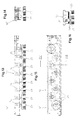
- FIG. 4 referred to 6, in which only the first tool unit 5 illustrated in different views is.
- this first tool unit 5 like any tool unit of the machining device 1 - its own tool storage frame 19 for arrangement, mounting and pivoting of the associated processing tool, i.e. in in this case the brush roller 6.
- the brush roller 6 is over their shaft ends 6a, 6b in two on this face Storage frame 19 hanging bearings attached down 20 rotatably mounted. That beyond the camp 20 extended a shaft end 6b of the brush roller 6 carries a non-rotatably attached drive wheel, which preferably in the form of a pulley or V-belt pulley 21 is formed.
- a non-rotatably attached drive wheel which preferably in the form of a pulley or V-belt pulley 21 is formed.
- this processing device 1 as an important feature a quick change device for optional mutual exchange which contains various tool units.
- the tool storage frame each tool unit of the machining device 1 the tool storage frame of all tool units in their shape and in their external dimensions are of the same design and belong to the other also a sub-frame of the main device frame 8, this receiving subframe like this is executed that every tool storage frame fits exactly in it of the different tool units the processing device 1 fixed, but replaceable can be installed.
- This tool storage frame 19 itself has essentially the shape of an elongated regular Rectangle of sufficient length.
- the first tool unit 5 (as well any other tool unit that can be installed there) during of the machining company, on the one hand, directly or permanently with the swing frame 14 and the other - about this Swing frame 14 - also firmly connected to the main frame 9, so this tool unit 5 - and any other firmly connected tool unit - both the Oscillating movements (double arrow 17) of the swing frame 14 as well as the vertical adjustment or adjustment movements (Double arrow 7) of the main frame 9.
- the lower ones are Ends of the swing frame 14 in the form of bends 14a - pointing inwards - bent inwards, see above that they the side members 19a of the tool storage frame 19 reach under, these bends at 14a their upward-facing sides in the form of slide rails (if necessary or appropriate with sliding material pads) are trained. If now the screws 22 out the tool storage frame 19 are unscrewed and the latter or the associated tool unit 5 is in the released state, then supports this tool storage frame 19 via its side members 19a accordingly on the bends or slide rails 14a.
- this first Tool unit 5 is the V-belt pulley 21 of the brush roller 6 in the area of one end the processing device 1. Accordingly, in suitably in or on the main device frame 8 for the rotary drive of this brush roller 6 one Drive device 23 fixedly attached by a drive connection, preferably a belt drive or V-belt drive 24 with the drive wheel or V-belt pulley 21 installed in the swing frame 14 first tool unit 5 (or any other built-in tool unit) in drive connection stands.
- a drive connection preferably a belt drive or V-belt drive 24 with the drive wheel or V-belt pulley 21 installed in the swing frame 14 first tool unit 5 (or any other built-in tool unit) in drive connection stands.
- the drive device 23 or a corresponding one Drive motor can generally be customized for an overall Drive speed of the brush roller 6 designed his; however, it can be particularly useful if this drive device 23 with a speed control is equipped so that the different Machining tools with those considered to be optimal Rotation speeds (also in adaptation to different materials) can be driven. there it can also be particularly advantageous if the drive device 23 is designed so that the each processing tool used (be it a Brush roller 6 or more, be it plate-shaped Machining tools / disc brushes, as explained in more detail if necessary, with reversible direction of rotation can be driven.
- a special feature of this processing device according to the invention 1 can generally be seen in the fact that one or each (if there are several of the same type and series-connected) processing zone this device 1 has at least one processing roller or brush roller 6 containing the first tool unit 5 and at least one group of plate-shaped Second machining tools Tool unit provided and these tool units optional, i.e. interchangeable for processing the workpiece surfaces 2a in the device 1 can be operated.
- this tool storage frame 19 ' the second tool unit 30 in the form of an elongated one regular rectangle, not only its shape, but also its external dimensions are the same or the same size as those of the tool storage frame 19 of the first tool unit 5.
- This tool storage frame 19 '- how 8 and 10 in particular clarify - pronounced and longitudinal members 19'a which can be freely gripped from the outside on, so that this tool storage frame 19 'in turn fits exactly into the same mounting subframe, So the swing frame 14 of the main device frame 8 fixed but interchangeable, in exactly the same way as above in Connection with the tool storage frame 19 of the first tool unit 5 (in particular with reference to FIG. 2) in the individual has been explained, what to avoid be referred from repetitions.
- Embodiment of the second tool unit 30 is provided that the plate brushes 25 on their as brush shafts 26 trained rotating shafts individually in the tool storage frame 19 'for example with the help of Rolling bearings 27 in the manner illustrated in Fig.10 are rotatably mounted.
- Two adjacent to each other Brush shafts 26 are on their plate brushes 25 opposite shaft ends 26a by a drive connection connected to each other with the drive first embodiment of the second tool unit 30 by a belt drive, preferably one Toothed belt drive 31 is formed.
- These are - as in particular 7 and 10 show - on the upper shaft ends 26a of the brush shafts 26 generally each two corresponding toothed belt pulleys 31a axially directly one above the other or a corresponding double disc non-rotatably attached.
- This angular gear 32 is thus - as shown in Figure 7 in particular - between the associated V-belt pulley 21 and the corresponding first tool-drive connection, i.e. the neighboring one Toothed belt drive 31 arranged, on this connection a further toothed belt drive 32a is provided (Fig. 7 and 9).
- Disc brushes 25 - viewed in plan - about are staggered to each other and that they are at least in relation to the workpiece transport direction (Arrow 4), but preferably also, as shown, overlap each other in the transverse direction.
- This evenly overlapping arrangement the plate brushes 25 can do this among them workpiece 2 transported through on its surface 2a of the plate brushes 25 or their brush trimmings 25a can be optimally processed.
- This brush plate assembly basically also applies to the following further described embodiments the second tool unit.
- each plate brush 25 assigned a separate drive motor 34 is, it is preferred, each drive motor 34 to be equipped with a separate speed control.
- the individual plate brushes 25 can on the downwardly projecting ends of the motor drive shafts 34a be attached so that the plate brushes 25 then again driven to rotate about vertical axes of rotation can be.
- the disc brushes 25 with their single drive motors 34 in its own tool carrier frame 19 'recorded and supported the shape and External dimensions to those of the above based on approximately the Fig. 7-10 described tool support frame 19 'correspond.
- the plate brushes 25 can all with of the same kind or individually or in groups with different ones Rotational speeds are driven.
- these plate brushes 25 are then infinitely adjustable Rotational speeds are driven, it also can also be an advantage if these plate brushes 25 optionally in one or the other direction of rotation can be driven, namely all plate brushes 25 each in one or the other direction of rotation or directed against each other individually or in groups.
- Disc brushes 25 individually, in groups or together against the workpiece surface 2a. This is for example, advantageous if the bristle trim 25a of the plate brushes worn to a certain extent is, i.e. there is the possibility of the plate brushes 25 according to their respective wear by an adjusted Readjustment.
- the surfaces according to this embodiment of the invention 2a of workpieces 2 in one and the same processing device 1 optionally by means of at least one Processing roller, preferably a brush roller 6 containing first tool unit 5 or - in exchange to do this - by means of a group of plate-shaped Processing tools, preferably disc brushes 25 containing second tool unit 30 machined become. It is then in each case corresponding Way, the brush roller 6 approximately in its radial Direction against the workpiece surfaces 2a, while the plate brushes 25 approximately in their axial Direction against the workpiece surfaces 2a are, in each case according to the double arrow 7 1 and 2.
- the workpieces 2 are then during processing their surfaces 2a with the help of Transport device 3 in the longitudinal direction under the processing tools, So the brush roller 6 or under transported along the plate brushes 25. Are there then the workpieces 2 are sufficiently firm or stationary deposited on the transport device 3, with it With the help of this transport device 3 continuously as required, batchwise or reversible relative to the processing tools are transported.
Abstract
Description
Die Erfindung betrifft ein Verfahren sowie eine Vorrichtung
zur Bearbeitung von Oberflächen von im wesentlichen
flachen Werkstücken, entsprechend dem Oberbegriff
des Anspruches 1 bzw. gemäß dem Oberbegriff des
Anspruches 12.The invention relates to a method and an apparatus
for processing surfaces of essentially
flat workpieces, according to the generic term
of claim 1 or according to the preamble of
Derartige Verfahren und Vorrichtungen werden sowohl für relativ große als auch für relativ kleine Werkstück-oberflächen, beispielsweise zum Reinigen, Schleifen und Polieren der Oberflächen selbst sowie auch zum Entgraten von Außen- und Innenrändern von in irgendeiner Weise ausgeschnittenen bzw. ausgestanzten, flachen Werkstücken verwendet, die beispielsweise aus Metallblech, Holzwerkstoffen, Kunststoffen u.dgl. hergestellt sein können.Such methods and devices are used both for relatively large as well as for relatively small workpiece surfaces, for example for cleaning, grinding and Polishing the surfaces themselves as well as deburring from outside and inside edges of in any Cut out or punched out flat Workpieces used, for example made of sheet metal, Wood-based materials, plastics and the like manufactured could be.
Zu den zuvor genannten Zwecken ist es aus der Praxis bereits bekannt, entsprechende Werkstück-Oberflächen mit rotierend antreibbaren Bearbeitungswerkzeugen zu bearbeiten, wobei die Werkstücke im allgemeinen unter den Werkzeugen entlangtransportiert und dabei die Werkzeuge gegen die Werkstück-Oberflächen angestellt werden können. Je nach der gewünschten Bearbeitungsart ist in der Bearbeitungsvorrichtung entweder wenigstens eine Bürstenwalze oder wenigstens ein umlaufendes Schleifband als Bearbeitungswerkzeug vorgesehen. Gerade bei der Verwendung von Bürstenwalzen und Schleifbändern kommt es besonders bei der Bearbeitung von relativ großen Werkstück-Oberflächen vielfach zu unerwünschten Streifenbildungen, weshalb diesen Bearbeitungswalzen und Schleifbändern zusätzlich zu ihrer umlaufenden Bewegung noch eine etwa quer zur Werkstück-Transportrichtung ausgerichtete Oszillationsbewegung erteilt wird, was jedoch vielfach zu ebenfalls unerwünschten wellenförmigen Streifen führt.For the aforementioned purposes, it is from practice already known, corresponding workpiece surfaces with rotating drivable processing tools edit, the workpieces generally under transported along the tools and thereby the tools against the workpiece surfaces can. Depending on the type of machining required, in the processing device either at least one Brush roller or at least one rotating sanding belt provided as a machining tool. Especially with the use of brush rollers and sanding belts it comes especially when editing from relative large workpiece surfaces are often undesirable Banding, which is why this processing rollers and grinding belts in addition to their orbital motion another roughly transverse to the workpiece transport direction aligned oscillatory movement is given however, which in many cases also leads to undesirable wavy shapes Strip leads.
Außerdem sind beispielsweise aus der US-A-51 05 583 und EP-A-919 331 Vorrichtungen bekannt, in denen eine Anzahl von um senkrechte Achsen rotierenden, tellerförmigen Bearbeitungswerkzeugen bzw. Bürsten vorgesehen sind, die neben ihrer Eigenrotation noch um wenigstens eine weitere gemeinsame Drehachse zusätzliche etwa planetenförmige Drehbewegungen ausführen können. Diese verschiedenen Drehbewegungen der tellerförmigen Bearbeitungswerkzeuge haben zur Folge, daß bei gleichzeitiger Vorschubbewegung des Werkstückes mehrere unterschiedliche Relativbewegungen stattfinden, wodurch in verschiedenen Oberflächenbereichen der Werkstücke zwangsläufig unterschiedlich intensive Oberflächenbearbeitungen vorgenommen werden. Abgesehen davon ist zu bedenken, daß diese bekannten Ausführungen wegen ihrer grundsätzlich um vertikale Achsen rotierenden Bearbeitungswerkzeuge nur für eine begrenzte Art von Oberflächenbearbeitungen zum Einsatz kommen können.In addition, for example from US-A-51 05 583 and EP-A-919 331 discloses devices in which a number of plate-shaped rotating around vertical axes Machining tools or brushes provided are, in addition to their own rotation by at least another common axis of rotation additional approximately planet-shaped Can perform rotary movements. This various rotary movements of the plate-shaped processing tools have the consequence that with simultaneous Feed movement of the workpiece several different Relative movements take place, whereby in different surface areas of the workpieces inevitably different intensive surface treatments be made. Apart from that is too consider that these known designs because of their basically processing tools rotating around vertical axes only for a limited type of surface processing can be used.
Der Erfindung liegt die Aufgabe zugrunde, ein Verfahren
gemäß dem Oberbegriff des Anspruches 1 sowie eine Vorrichtung
entsprechend dem Oberbegriff des Anspruches 12
so auszubilden, daß die Bearbeitungsvorrichtung bei relativ
niedrigem Vorrichtungsaufwand sowie mit optimalem
Bearbeitungsergebnis äußerst zuverlässig für sehr vielfältige
Oberflächenbearbeitungsarten verwendet werden
kann. The invention has for its object a method
according to the preamble of claim 1 and a device
according to the preamble of
Diese Aufgabe wird verfahrenstechnisch durch das Kennzeichen
des Anspruches 1 und vorrichtungsmäßig durch
das Kennzeichen des Anspruches 13 gelöst.This task is procedurally identified by the indicator
of claim 1 and device-wise
solved the characterizing part of
Vorteilhafte Ausgestaltungen und Weiterbildungen der Erfindung sind Gegenstand der Unteransprüche.Advantageous refinements and developments of Invention are the subject of the dependent claims.
Ein Grundgedanke des erfindungsgemäßen Verfahrens wird darin gesehen, daß die Werkstück-Oberflächen in wenigstens einer Bearbeitungszone derselben Bearbeitungsvorrichtung wahlweise mittels einer wenigstens eine Bearbeitungswalze enthaltenden ersten Werkzeugeinheit oder einer eine Gruppe von tellerförmigen Bearbeitungswerkzeugen enthaltenden zweiten Werkzeugeinheit bearbeitet werden, wobei die Bearbeitungswalze etwa in ihrer radialen Richtung und die tellerförmigen Bearbeitungswerkzeuge etwa in ihrer axialen Richtung gegen die Werkstück-oberflächen angestellt werden.A basic idea of the method according to the invention becomes seen in that the workpiece surfaces in at least a processing zone of the same processing device optionally by means of at least one processing roller containing first tool unit or one a group of plate-shaped processing tools containing second tool unit processed be, the processing roller approximately in its radial Direction and the plate-shaped editing tools approximately in their axial direction against the Workpiece surfaces.
Diesem erfindungsgemäßen Verfahren liegt die Erkenntnis zugrunde, daß unterschiedliche Werkstück-Oberflächen und unterschiedliche Werkstoffarten jeweils nur mit entsprechend angepaßten Bearbeitungswerkzeugen optimal bearbeitet werden können. Dabei kann eine relativ große Gruppe von Oberflächenarten und Werkstoffarten besonders günstig mit walzenförmigen Bearbeitungswerkzeugen und eine weitere große Gruppe von Oberflächenarten und Werkstoffarten besonders günstig mit tellerförmigen Bearbeitungswerkzeugen bearbeitet werden, wobei sich die genannten Gruppen teilweise auch überschneiden können. Wenn dementsprechend in wenigstens einer Bearbeitungszone ein und derselben Bearbeitungsvorrichtung die wenigstens eine Bearbeitungswalze enthaltende erste Werkzeugeinheit und die eine Gruppe von tellerförmigen Bearbeitungswerkzeugen enthaltende zweite Werkzeugeinheit leicht und relativ rasch gegeneinander ausgetauscht werden können, dann können darin äußerst zuverlässig und mit optimalem Bearbeitungsergebnis sehr vielfältige Oberflächen-Bearbeitungsarten (sei es entsprechend der Größe und Form der Oberflächen, sei es in bezug auf die Werkstoffart) durchgeführt werden. Dies erweist sich vor allem auch dann als besonders vorteilhaft, wenn ein Anwender einer solchen Bearbeitungsvorrichtung nur verhältnismäßig kleine Werkstückmengen mit den jeweils spezifischen Oberflächenbearbeitungsarten bzw. Werkstoffarten (mit den jeweils am besten geeigneten Bearbeitungswerkzeugen) bearbeitet und somit diese Bearbeitungsvorrichtung bei Ausrüstung nur mit walzenförmigen oder nur mit tellerförmigen Bearbeitungswerkzeugen vollkommen unzureichend ausgelastet wäre.The knowledge lies in this method according to the invention based on the fact that different workpiece surfaces and different types of materials only with optimally adapted processing tools can be edited. This can be a relatively large Group of surface types and types of materials especially cheap with roller-shaped processing tools and another large group of surface types and Material types particularly cheap with plate-shaped processing tools are processed, with the mentioned groups can partially overlap. If so in at least one processing zone one and the same processing device the at least a first tool unit containing a processing roller and the one group of plate-shaped machining tools containing second tool unit exchanged easily and relatively quickly can be extremely reliable and very diverse with optimal processing results Surface processing types (be it according to the Size and shape of the surfaces, be it in relation to the Type of material). It turns out especially as particularly advantageous if a Users of such a processing device only proportionately small quantities of workpieces with each specific types of surface processing or types of material (with the most suitable processing tools) edited and thus this processing device if equipped only with roller-shaped or only with plate-shaped processing tools would be completely underutilized.
Bei diesem erfindungsgemäßen Verfahren ist es dabei besonders vorteilhaft, wenn für jede Werkzeugeinheit ein Werkzeug-Lagerungsrahmen mit wenigsten teilweise gleicher äußerer Formgebung verwendet wird und jeder Werkzeug-Lagerungsrahmen in denselben Aufnahme-Teilrahmen eines Hauptvorrichtungsgestelles schnell austauschbar eingebaut bzw. ein- und ausgebaut werden kann.It is special in this method according to the invention advantageous if one for each tool unit Tool storage frame with at least partially the same outer shape is used and each tool storage frame in the same recording subframe of a main fixture rack quickly replaceable can be installed or installed and removed.
Gemäß einer besonders bevorzugten Ausführungsform des erfindungsgemäßen Verfahrens werden in der ersten Werkzeugeinheit eine Bürstenwalze und in der zweiten Werkzeugeinheit als tellerförmige Bearbeitungswerkzeuge stirnseitig gegen die Werkstück-Oberfläche anstellbare Tellerbürsten verwendet. Bürstenförmige Bearbeitungswerkzeuge haben sich bei der praktischen Anwendung als besonders vielseitig verwendbar erwiesen, wobei zusätzlich zu beachten ist, daß zum einen die Bürstenwalzen und die Tellerbürsten jeweils für recht unterschiedliche Bearbeitungseingriffe geeignet sind und daß zum andern zusätzlich noch die Möglichkeit besteht, sowohl bei Bürstenwalzen als auch bei Tellerbürsten spezifisch angepaßtes Borstenmaterial (Borstenbesatz) zu verwenden, um mehr oder weniger intensive Bearbeitungseingriffe erzeugen zu können.According to a particularly preferred embodiment of the The inventive method are in the first tool unit a brush roller and in the second tool unit as plate-shaped processing tools adjustable against the workpiece surface Disc brushes used. Brush-shaped editing tools have proven themselves in practical use proven to be particularly versatile, with additional it should be noted that on the one hand the brush rollers and the plate brushes each for quite different ones Editing interventions are suitable and that to the other in addition there is the possibility of both specific for brush rollers as well as for plate brushes to use adapted bristle material (bristle trim), for more or less intensive editing to be able to generate.
Darüber hinaus bestehen in vorteilhafter Weise noch vielfältige Einwirkungsmöglichkeiten in bezug auf die Drehbewegungen und die Anstellmöglichkeiten sowohl der Bürstenwalzen als auch der Tellerbürsten, was aus der späteren Beschreibung verschiedener Ausführungsbeispiele noch deutlich wird.In addition, advantageously still exist diverse possibilities of action in relation to the Rotary movements and the adjustment possibilities of both Brush rollers as well as the plate brushes, what from the later description of various embodiments still becomes clear.
Die erfindungsgemäß ausgeführte Vorrichtung zeichnet sich dadurch aus, daß für wenigstens eine Bearbeitungszone dieser Vorrichtung eine wenigstens eine Bearbeitungswalze enthaltende erste Werkzeugeinheit und eine wenigstens eine Gruppe von tellerförmigen Bearbeitungswerkzeugen enthaltende zweite Werkzeugeinheit vorgesehen und diese Werkzeugeinheiten wahlweise zur Bearbeitung der Werkstück-oberflächen betreibbar sind, wobei die Bearbeitungswalze mit ihrer Außenumfangsfläche in etwa radialer Richtung und die tellerförmigen Bearbeitungswerkzeuge mit ihren äußeren Stirnseiten in etwa axialer Richtung gegen die Werkstück-Oberflächen anstellbar sind.The device designed according to the invention draws is characterized in that for at least one processing zone this device has at least one processing roller containing first tool unit and one at least one group of plate-shaped processing tools containing second tool unit provided and these tool units optionally for processing the workpiece surfaces are operable, whereby the processing roller with its outer peripheral surface in about radial direction and the plate-shaped processing tools with their outer faces roughly adjustable in the axial direction against the workpiece surfaces are.
Gemäß einer besonders vorteilhaften Ausgestaltung dieser Vorrichtung weist jede Werkzeugeinheit einen eigenen Werkzeug-Lagerungsrahmen für die Anordnung und Halterung der Bearbeitungswerkzeuge auf, und es ist eine Schnellwechseleinrichtung zum wahlweisen gegenseitigen Austausch der verschiedenen Werkzeugeinheiten vorgesehen, wobei jeder Werkzeug-Lagerungsrahmen in seiner Formgebung und in seinen Außenabmessungen gleichartig so ausgebildet ist, daß er genau passend in denselben Aufnahme-Teilrahmen des Hauptvorrichtungsgestelles fest, jedoch auswechselbar einbaubar ist. Durch diese Ausgestaltung können somit im Bedarfsfalle sowie ggf. im raschen Wechsel sehr vielfältige bzw. unterschiedliche Bearbeitungsarten mit jeweils optimalem Ergebnis bearbeitet werden, da jeweils eine optimal dem gewünschten Bearbeitungsergebnis und den jeweiligen Werkstückarten angepaßte Werkzeugeinheit - wegen der raschen Austauschbarkeit bzw. Auswechselbarkeit der Werkzeugeinheiten - zur Anwendung kommen kann.According to a particularly advantageous embodiment of this Each tool unit has its own device Tool storage frame for arrangement and mounting of the editing tools on and it's one Quick change device for optional mutual Exchange of the various tool units provided each tool storage frame in its Shape and similar in its outer dimensions is designed so that it fits exactly in the same Sub-frame of the main device frame fixed but interchangeable. Through this If necessary, and if necessary, in rapid change very diverse or different Types of processing with optimal results can be processed, since one optimally corresponds to the desired one Machining result and the respective workpiece types adapted tool unit - because of the quick Interchangeability or interchangeability of the tool units - can be used.
Gerade bei dieser Ausbildung mit Schnellwechseleinrichtung erweist sich eine weitere Ausgestaltung der Erfindung als sehr vorteilhaft, wonach jede Werkzeugeinheit über ihren Werkzeug-Lagerungsrahmen im Betriebszustand fest mit dem Aufnahme-Teilrahmen verschraubt und im gelösten Einbau- und Ausbauzustand auf Gleitschienen dieses Aufnahme-Teilrahmens derart abgestützt und geführt ist, daß sie von einer Längsseite der Vorrichtung her schnell ein- und ausgebaut und damit ein rascher Wechsel der Werkzeugeinheiten vorgenommen werden kann.Especially with this training with quick-change device a further embodiment of the invention has been found as very beneficial, after which each tool unit about their tool storage frame in the operating state firmly screwed to the sub-frame and loosened Installation and removal condition on slide rails this Supporting sub-frame supported and guided in this way is that it is from a long side of the device quickly installed and removed and thus a quick change the tool units can be made.
Die Erfindung sei nachfolgend anhand einiger in der Zeichnung veranschaulichter Ausführungsbeispiele näher erläutert. In dieser Zeichnung zeigen
- Fig.1
- eine vereinfachte Seitenansicht der erfindungsgemäßen Bearbeitungsvorrichtung mit einer eingebauten ersten Werkzeugeinheit (mit Bürstenwalze);
- Fig.2
- eine Stirnansicht der Bearbeitungsvorrichtung gemäß Fig.1;
- Fig.3
- eine Aufsicht auf die Bearbeitungsvorrichtung gemäß Fig.1;
- Fig.4
- eine Seitenansicht der ersten Werkzeugeinheit mit einer Bürstenwalze;
- Fig.5
- eine Stirnansicht der ersten Werkzeugeinheit gemäß Fig.4;
- Fig.6
- eine Aufsicht auf die erste Werkzeugeinheit gemäß Fig.4;
- Fig.7, 8 und 9
- Seitenansicht, Stirnansicht und Aufsicht einer zweiten Werkzeugeinheit mit einer Anzahl von Tellerbürsten, gemäß einem ersten Ausführungsbeispiel, nach dem alle Tellerbürsten durch Riementriebe angetrieben werden;
- Fig.10
- eine vergrößerte Querschnittsansicht entlang der Linie X-X in Fig.9;
- Fig.11
- eine rein schematische Teil-Grundrißansicht auf die zweite Werkzeugeinheit, zur Erläuterung der Tellerbürsten-Zusammenordnung;
- Fig.12
- eine ähnliche Aufsicht auf die zweite Werkzeugeinheit wie Fig.9, jedoch zur Erläuterung eines zweiten Ausführungsbeispieles, bei dem die Tellerbürsten durch Zahnräder (Stirnräder) miteinander antriebsverbunden sind;
- Fig.13, 14 und 15
- Seitenansicht, Stirnansicht und Aufsicht der zweiten Werkzeugeinheit gemäß einem dritten Ausführungsbeispiel, nach dem die Tellerbürsten mit gesonderten Einzelantriebsmotoren versehen sind;
- Fig.16
- eine Querschnittsansicht entsprechend der Linie XVI-XVI in Fig.15.
- Fig.1
- a simplified side view of the processing device according to the invention with a built-in first tool unit (with brush roller);
- Fig.2
- an end view of the processing device according to Figure 1;
- Figure 3
- a plan view of the processing device according to Figure 1;
- Figure 4
- a side view of the first tool unit with a brush roller;
- Figure 5
- an end view of the first tool unit according to Figure 4;
- Figure 6
- a plan view of the first tool unit according to Figure 4;
- Fig. 7, 8 and 9
- Side view, front view and top view of a second tool unit with a number of plate brushes, according to a first embodiment, according to which all plate brushes are driven by belt drives;
- Figure 10
- an enlarged cross-sectional view taken along line XX in Figure 9;
- Figure 11
- a purely schematic partial plan view of the second tool unit, to explain the plate brush assembly;
- Figure 12
- a similar view of the second tool unit as Figure 9, but to explain a second embodiment in which the plate brushes are connected to each other by gears (spur gears);
- Fig. 13, 14 and 15
- Side view, front view and top view of the second tool unit according to a third exemplary embodiment, according to which the plate brushes are provided with separate individual drive motors;
- Figure 16
- a cross-sectional view along the line XVI-XVI in Fig.15.
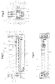
Der Gesamtaufbau der erfindungsgemäßen Bearbeitungsvorrichtung 1 sei zunächst anhand der Fig.1 bis 3 erläutert, wobei hinzugefügt sei, daß dort im wesentlichen - in teilweise vereinfachter Form - nur die Vorrichtungsteile veranschaulicht sind, die zur Erläuterung der Erfindung als notwendig angesehen werden.The overall structure of the processing device according to the invention 1 is first explained with reference to FIGS. 1 to 3, adding that there essentially - in a partially simplified form - only the device parts are illustrated to illustrate the invention be considered necessary.
Diese Bearbeitungsvorrichtung 1 dient zur Bearbeitung von Oberflächen 2a von beliebigen, im wesentlichen flachen Werkstücken 2 (z.B. aus Metallblech, Holzwerkstoffen, Kunststoffen u.dgl.), die während ihrer Bearbeitung auf einer geeigneten Transporteinrichtung, beispielsweise einem in Fig.1 nur angedeuteten Förderband 3 beispielsweise in Richtung des Pfeiles 4 (Fig.2) unter einem oder mehreren Bearbeitungswerkzeugen einer jeweils eingebauten Werkzeugeinheit entlangtransportiert werden.This processing device 1 is used for processing of surfaces 2a of any, essentially flat Workpieces 2 (e.g. made of sheet metal, wood materials, Plastics and the like), which during their processing on a suitable transport device, for example a conveyor belt only indicated in Fig.1 3 for example in the direction of arrow 4 (Fig.2) below one or more processing tools each installed tool unit transported along become.
Bei der Darstellung in den Fig.1 bis 3 sei angenommen,
daß in die Bearbeitungsvorrichtung 1 eine erste Werkzeugeinheit
5 eingebaut ist, in der eine Bürstenwalze 6
als Bearbeitungswalze bzw. walzenförmiges Bearbeitungswerkzeug
rotierend antreibbar angeordnet ist. Wie später
noch im einzelnen erläutert wird, kann die Bürstenwalze
6 - wie im Prinzip an sich bekannt - mit ihrer
Außenumfangsfläche in etwa radialer Richtung gegen die
Werkstück-Oberfläche 2a angestellt bzw. davon abgehoben
werden, d.h. die Bürstenwalze 6 ist mit der gesamten
ersten Werkzeugeinheit 5 in Richtung des Doppelpfeiles
7, also in vertikaler Richtung, in ausreichendem Maße
und genau einstellbar.In the illustration in FIGS. 1 to 3 it is assumed
that in the processing device 1 a
Die Bearbeitungsvorrichtung 1 enthält ein Hauptvorrichtungsgestell
8, in dem ein Hauptrahmen 9 mit Hilfe von
zwei Verstellgetrieben (z.B. Schneckengetrieben) 10 und
zugehörigen Verstellspindeln 11 in vertikaler Richtung
und damit höhenverstellbar ist, um die vertikale Einstellbarkeit
bzw. das Anstellen der jeweiligen Werkzeuge
(z.B. Bürstenwalze 6) entsprechend Doppelpfeil 7
gegenüber den Werkstück-Oberflächen 2a gewährleisten zu
können. Die Verstellspindeln 11 können dabei etwa in
Hohlwellen der Verstellgetriebe 10 axialverstellbar gelagert
sein. Diese axiale Verstellung (und damit die
Höhenverstellbarkeit des Hauptrahmens 9 mit den daran
angeordneten Vorrichtungsteilen) kann durch jede geeignete
Antriebseinrichtung geschehen; in diesem Ausführungsbeispiel
sind dazu Druckluftzylinder 12 vorgesehen.
Der axiale Verstellweg kann ferner durch geeignete
und vorzugsweise einstellbare Anschläge 13
(Fig.2) begrenzt werden.The processing device 1 includes a
Die zuvor erläuterte axiale Verstellung kann gewissermaßen
als eine doppelte Axialverstellung und damit als
doppelte Höhenverstellung in Richtung des Doppelpfeiles
in der Weise ausgeführt sein, daß die jeweils im Hauptvorrichtungsgestell
8 eingebauten Bearbeitungswerkzeuge
(Bürstenwalze 6 oder die noch später zu erläuternden
Tellerbürsten 25) auf wenigstens zwei Verstellwegen
vertikal gegenüber den Werkzeugoberflächen 2a verstellt
werden können, von denen der erste Verstellweg die allgemeine
Anstell- bzw. Nachstellbarkeit und der zweite
Verstellweg eine vorbestimmbare Hubgröße bildet, um die
die Bearbeitungswerkzeuge von den Werkstück-oberflächen
2a in eine inaktive Außereingriffsstellung angehoben
werden. Letzteres kann beispielsweise dann sinnvoll und
erforderlich sein, wenn Werkstücke 2 bei einer hin- und
hergehenden Relativbewegung zwischen den Bearbeitungswerkzeugen
und den Werkstück-oberflächen bearbeitet und
dabei die Bearbeitungswerkzeuge bei einem Zurückfahren
in eine Ausgangsstellung oder dergleichen keine Bearbeitung
der Werkstück-oberflächen ausführen, also inaktiv
sein sollen. In dieser Inaktiv- bzw. Außereingriffsstellung
genügt es im allgemeinen, wenn die Werkzeuge
nur um wenige Millimeter (z.B. 3 mm) von den
Werkstück-oberflächen abgehoben bzw. entfernt sind.
Dieses Anheben der Bearbeitungswerkzeuge kann automatisch
mit dem Umsteuern der Relativbewegungen (z.B. zum
Zurückfahren) erfolgen. Unabhängig von diesem Anheben
der Bearbeitungswerkzeuge um die vorbestimmbare bzw.
voreinstellbare Hubgröße können die Bearbeitungswerkzeuge
mit Hilfe der Verstellgetriebe 10 und der zugehörigen
Verstellspindeln 11 über den ersten Verstellweg
mit ausreichend großen Verstellmaßen beliebig allgemein
angestellt bzw. nachgestellt werden, wenn dies erforderlich
wird (z.B. bei unterschiedlichen Werkstückdicken,
nach Abnutzung der Borstenbesätze der Bearbeitungswerkzeuge
usw.).The axial adjustment explained above can be used to a certain extent
as a double axial adjustment and thus as
double height adjustment in the direction of the double arrow
be carried out in such a way that in each case in the
Im Hauptrahmen 9 ist ferner ein Schwingrahmen 14 angeordnet,
der an seinen Stirnenden durch Längsführungszapfen
15 o.dgl. in ortsfesten Führungsbuchsen 16 in
Richtung des gestrichelten Doppelpfeiles 17 für eine
etwa quer zum Werkstück 2 bzw. zu dessen Transportrichtung
gemäß Pfeil 4 verlaufende Hin- und Herbewegung gelagert
ist, d.h. dieser Schwingrahmen 14 kann eine entsprechende
querverlaufende hin- und hergehende Relativbewegung
zwischen den Werkstücken 2 und den Werkzeugen
(z.B. Walze 6) ausführen. Zu diesem Zweck ist dem
Schwingrahmen 14 auf dem Hauptrahmen 9 ein geeigneter
Oszillationsantrieb 18 zugeordnet, der u.a. einen Antriebsmotor
18a, ein Winkelgetriebe 18b und einen Kurbeltrieb
18c enthalten kann. Selbstverständlich könnten
auch andere geeignete Oszillationsantriebe vorgesehen
sein, wie z.B. ein Pneumatikzylinder oder ein Elektrozylinder.A
Für die weitere Erläuterung sei zunächst auf die Fig.4
bis 6 Bezug genommen, in denen nur die erste Werkzeugeinheit
5 in verschiedenen Ansichten veranschaulicht
ist. Hier ist zu erkennen, daß diese erste Werkzeugeinheit
5 - wie überhaupt jede Werkzeugeinheit der Bearbeitungsvorrichtung
1 - einen eigenen Werkzeug-Lagerungsrahmen
19 für die Anordnung, Halterung und Drehlagerung
des zugehörigen Bearbeitungswerkzeuges, also in
diesem Falle der Bürstenwalze 6 aufweist. In diesem
Werkzeug-Lagerungsrahmen 19 ist die Bürstenwalze 6 über
ihre Wellenenden 6a, 6b in zwei stirnseitig an diesem
Lagerungsrahmen 19 nach unten hängend befestigten Lagern
20 drehbar gelagert. Das über das Lager 20 hinaus
verlängerte eine Wellenende 6b der Bürstenwalze 6 trägt
ein drehfest darauf angebrachtes Antriebsrad, das vorzugsweise
in Form einer Riemenscheibe bzw. Keilriemenscheibe
21 ausgebildet ist. Nimmt man unter Beachtung
der vorhergehenden Erläuterungen zu den Fig.4 bis 6
nochmals Bezug auf die Gesamtdarstellung der Bearbeitungsvorrichtung
gemäß den Fig.1 bis 3, dann sei
zunächst darauf hingewiesen, daß diese Bearbeitungsvorrichtung
1 als ein wichtiges Merkmal eine Schnellwechseleinrichtung
zum wahlweisen gegenseitigen Austausch
der verschiedenen Werkzeugeinheiten enthält. Hierzu gehört
zum einen grundsätzlich der Werkzeug-Lagerungsrahmen
jeder Werkzeugeinheit der Bearbeitungsvorrichtung
1, wobei die Werkzeug-Lagerungsrahmen aller Werkzeugeinheiten
in ihrer Formgebung und in ihren Außenabmessungen
gleichartig ausgebildet sind, und zum andern gehört
dazu ein Aufnahme-Teilrahmen des Hauptvorrichtungsgestelles
8, wobei dieser Aufnahme-Teilrahmen so
ausgeführt ist, daß in ihm genau passend jeder Werkzeug-Lagerungsrahmen
der verschiedenen Werkzeugeinheiten
der Bearbeitungsvorrichtung 1 fest, jedoch auswechselbar
eingebaut werden kann.For further explanation, first refer to FIG. 4
referred to 6, in which only the
Dieser Werkzeug-Lagerungsrahmen 19 selbst weist im wesentlichen
die Form eines langgestreckten regelmäßigen
Rechteckes ausreichender Länge auf.This
Betrachtet man im zuvor genannten Sinne somit nochmals
die ganze Bearbeitungsvorrichtung 1, dann erkennt man
insbesondere in Fig.2 zunächst, daß der anhand der
Fig.4 bis 6 erläuterte Werkzeug-Lagerungsrahmen 19 in
dem bereits erwähnten Aufnahme-Teilrahmen aufgenommen
ist, der vorzugsweise (nach diesem Ausführungsbeispiel)
durch den weiter oben erläuterten Schwingrahmen 14 gebildet
ist. Bei dem in den Fig.1 und 2 veranschaulichten
Betriebszustand der Bearbeitungsvorrichtung
1 ist zu erkennen, daß die erste Werkzeugeinheit 5
über ihren Werkzeug-Lagerungsrahmen 19 fest mit dem
Schwingrahmen (= Aufnahme-Teilrahmen) 14 mit Hilfe von
Schrauben 22 fest eingebaut bzw. verschraubt ist. Auf
diese Weise ist die erste Werkzeugeinheit 5 (wie auch
jede andere dort einbaubare Werkzeugeinheit) während
des Bearbeitungsbetriebes zum einen direkt bzw. fest
mit dem Schwingrahmen 14 und zum andern - über diesen
Schwingrahmen 14 - auch fest mit dem Hauptrahmen 9 verbunden,
so daß diese Werkzeugeinheit 5 - und jede andere
damit fest verbundene Werkzeugeinheit - sowohl die
Oszillationsbewegungen (Doppelpfeil 17) des Schwingrahmens
14 als auch die vertikalen Einstell- bzw. Anstellbewegungen
(Doppelpfeil 7) des Hauptrahmens 9 mitmacht.If you look at it again in the aforementioned sense
the whole processing device 1, then you can see
in particular in Figure 2 first that the on the basis of
Fig. 4 to 6 explained
Wie nun ferner in Fig.2 erkennbar ist, sind die unteren
Enden des Schwingrahmens 14 in Form von Abwinklungen
14a - gegeneinanderweisend - nach einwärts gebogen, so
daß sie die Längsträger 19a des Werkzeug-Lagerungsrahmens
19 untergreifen, wobei diese Abwinklungen 14a an
ihren nach oben weisenden Seiten in Form von Gleitschienen
(ggf. bzw. zweckmäßig mit Gleitmaterialauflagen)
ausgebildet sind. Wenn nun die Schrauben 22 aus
dem Werkzeug-Lagerungsrahmen 19 herausgeschraubt sind
und sich letzterer bzw. die zugehörige Werkzeugeinheit
5 sich im gelösten Zustand befindet, dann stützt sich
dieser Werkzeug-Lagerungsrahmen 19 über seine Längsträger
19a entsprechend auf den Abwinklungen bzw. Gleitschienen
14a ab. In diesem gelösten Einbau- bzw. Ausbauzustand
kann die Werkzeugeinheit 5 bzw. jede Werkzeugeinheit
- unter Abstützung und Führung auf den
Gleitschienen 14a - von einer Längsseite (bzw. einem
Stirnende) der Bearbeitungsvorrichtung 1 her schnell
ein- und ausgebaut werden bzw. kann jede Werkzeugeinheit
gegen eine andere Werkzeugeinheit ausgewechselt
werden. Eine auf diese Weise neu eingebaute Werkzeugeinheit
stützt sich nach ihrem Einschieben in den Aufnahme-Teilrahmen
bzw. Schwingrahmen 14 zunächst auf den
Gleitschienen 14a ab und kann dann, wenn sie sich in
ihrer genauen Einbauposition befindet, mit Hilfe der
Schrauben 22 wieder fest von unten her an den Schwingrahmen
14 angebaut werden, so daß sie sich dann in ihrem
Betriebszustand in der Bearbeitungsvorrichtung 1
befindet.As can now also be seen in FIG. 2, the lower ones are
Ends of the
Im eingebauten Zustand (Fig.1 und 2) dieser ersten
Werkzeugeinheit 5 befindet sich die Keilriemenscheibe
21 der Bürstenwalze 6 im Bereich des einen Stirnendes
der Bearbeitungsvorrichtung 1. Dementsprechend ist in
geeigneter Weise im bzw. am Hauptvorrichtungsgestell 8
für den Drehantrieb dieser Bürstenwalze 6 eine
Antriebseinrichtung 23 ortsfest angebracht, die durch
eine Antriebsverbindung, vorzugsweise einem Riementrieb
bzw. Keilriementrieb 24 mit dem Antriebsrad bzw. der
Keilriemenscheibe 21 dieser im Schwingrahmen 14 eingebauten
ersten Werkzeugeinheit 5 (oder jeder anderen
eingebauten Werkzeugeinheit) in Antriebsverbindung
steht. Die Antriebseinrichtung 23 bzw. ein entsprechender
Antriebsmotor kann generell für eine insgesamt angepaßte
Antriebsdrehzahl der Bürstenwalze 6 ausgelegt
sein; es kann jedoch besonders zweckmäßig sein, wenn
diese Antriebseinrichtung 23 mit einer Drehzahlregelung
ausgestattet ist, so daß die verschiedenen
Bearbeitungswerkzeuge mit den jeweils als optimal angesehenen
Drehgeschwindigkeiten (auch in Anpassung an
verschiedene Werkstoffe) angetrieben werden können. Dabei
kann es weiterhin besonders vorteilhaft sein, wenn
die Antriebseinrichtung 23 so ausgeführt ist, daß die
jeweils verwendeten Bearbeitungswerkzeuge (sei es eine
Bürstenwalze 6 oder mehr, seien es tellerförmige
Bearbeitungswerkzeuge/Tellerbürsten, wie noch näher erläutert
wird) im Bedarfsfalle mit umkehrbarer Drehrichtung
angetrieben werden können.In the installed state (Fig. 1 and 2) this
Ein besonderes Merkmal dieser erfindungsgemäßen Bearbeitungsvorrichtung
1 ist generell darin zu sehen, daß
eine bzw. jede (bei gegebenenfalls mehreren gleichartigen
und hintereinandergeschalteten) Bearbeitungszone
dieser Vorrichtung 1 eine wenigstens eine Bearbeitungswalze
bzw. Bürstenwalze 6 enthaltende erste Werkzeugeinheit
5 und eine wenigstens eine Gruppe von tellerförmigen
Bearbeitungswerkzeugen enthaltende zweite
Werkzeugeinheit vorgesehen und diese Werkzeugeinheiten
wahlweise, d.h. gegeneinander auswechselbar zur Bearbeitung
der Werkstück-oberflächen 2a in der Vorrichtung
1 betrieben werden können.A special feature of this processing device according to the invention
1 can generally be seen in the fact that
one or each (if there are several of the same type
and series-connected) processing zone
this device 1 has at least one processing roller
or
Während nun anhand der Fig.1 bis 6 bisher die Bearbeitungsvorrichtung
1 im Zusammenhang mit einer darin auswechselbar
eingebauten bzw. einbaubaren, eine Bürstenwalze
6 enthaltenden ersten Werkzeugeinheit 5 erläutert
worden ist, sei nachfolgend anhand der weiteren Figuren
beschrieben, daß und wie eine zweite Werkzeugeinheit
mit tellerförmigen Bearbeitungswerkzeugen in Form von
Tellerbürsten auswechselbar in die Bearbeitungsvorrichtung
1 eingebaut werden kann. While now the processing device based on Figures 1 to 6
1 in connection with one interchangeable
built-in or built-in, a
Bevor auf die verschiedenen Ausführungsbeispiele dieser
zweiten Werkzeugeinheit eingegangen wird, sei zunächst
vorausgeschickt, daß in dieser zweiten Werkzeugeinheit
- egal bei welchem der verschiedenen Ausführungsbeispiele
- eine ausreichende Anzahl von tellerförmigen
Bearbeitungswerkzeugen in Form von Tellerbürsten 25
vorgesehen ist, die alle gleichartig ausgeführt sind,
im wesentlichen vertikal angeordnete Bürstenwellen 26
aufweisen und dementsprechend um vertikale Drehachsen
drehbar angeordnet sind, wobei sie - wie in den verschiedenen
Figuren zu erkennen - zumindest an ihren gegen
die zu bearbeitenden Werkstück-oberflächen, also
nach unten gerichteten äußeren Stirnseiten einen geeigneten
Borstenbesatz 25a aufweisen. Demgegenüber ist
am Außenumfangsmantel der Bürstenwalze 6 - wie in den
Fig.1, 2 und 4 angedeutet - ein etwa radialer Borstenbesatz
6c angebracht.Before going on to the different embodiments of this
second tool unit is discussed first
sent that in this second tool unit
- regardless of which of the different embodiments
- a sufficient number of plate-shaped
Machining tools in the form of plate brushes 25
is provided, which are all designed in the same way,
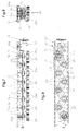
Insbesondere anhand der Fig.7 bis 10 sei nun ein erstes
Ausführungsbeispiel der zweiten Werkzeugeinheit 30 erläutert,
in der eine Anzahl von Tellerbürsten 25 vorgesehen
ist. Diese zweite Werkzeugeinheit 30 weist
zunächst - wie bereits weiter oben im Zusammenhang mit
der ersten Werkzeugeinheit 1 teilweise erläutert -
einen eigenen Werkzeug-Lagerungsrahmen 19' für die Anordnung
und Halterung der zugehörigen Bearbeitungswerkzeuge,
also der Tellerbürsten 25 auf. Dieser Werkzeug-Lagerungsrahmen
19' bildet wiederum nicht nur einen
Teil der zugehörigen Werkzeugeinheit, also der zweiten
Werkzeugeinheit 30, sondern auch einen Teil der bereits
weiter oben beschriebenen Schnellwechseleinrichtung der
Bearbeitungsvorrichtung 1, um einen wahlweisen gegenseitigen
Austausch der verschiedenen Werkzeugeinheiten
zu ermöglichen. Wie ein Vergleich der zeichnerischen
Darstellungen in den Fig.4 bis 5 der ersten Werkzeugeinheit
5, einerseits, und der Fig.7 bis 9 für diese
zweite Werkzeugeinheit, andererseits, gut erkennen
läßt, weist auch dieser Werkzeug-Lagerungsrahmen 19'
der zweiten Werkzeugeinheit 30 die Form eines langgestreckten
regelmäßigen Rechteckes auf, wobei nicht nur
seine Formgebung, sondern auch seine Außenabmessungen
gleichartig bzw. gleich groß sind wie jene des Werkzeug-Lagerungsrahmens
19 der ersten Werkzeugeinheit 5.
Dabei weist dieser Werkzeug-Lagerungsrahmen 19' - wie
besonders die Fig.8 und 10 verdeutlichen - ausgeprägte
und von außen her frei untergreifbare Längsträger 19'a
auf, so daß dieser Werkzeug-Lagerungsrahmen 19' wiederum
genau passend in denselben Aufnahme-Teilrahmen,
also den Schwingrahmen 14 des Hauptvorrichtungsgestelles
8 fest jedoch auswechselbar eingebaut werden kann,
und zwar in genau derselben Weise wie es weiter oben im
Zusammenhang mit dem Werkzeug-Lagerungsrahmen 19 der
ersten Werkzeugeinheit 5 (insbesondere anhand Fig.2) im
einzelnen erläutert worden ist, worauf zur Vermeidung
von Wiederholungen verwiesen sei.7 to 10 in particular, let us now consider a first one
Exemplary embodiment of the
Bei dem in den Fig.7 bis 10 veranschaulichten ersten
Ausführungsbeispiel der zweiten Werkzeugeinheit 30 ist
vorgesehen, daß die Tellerbürsten 25 über ihre als Bürstenwellen
26 ausgebildeten Drehwellen einzeln im Werkzeug-Lagerungsrahmen
19' beispielsweise mit Hilfe von
Wälzlagern 27 in der in Fig.10 veranschaulichten Weise
drehbar gelagert sind. Je zwei einander benachbarte
Bürstenwellen 26 sind dabei an ihren den Tellerbürsten
25 entgegengesetzten Wellenenden 26a durch eine Triebverbindung
miteinander antriebsverbunden, die bei diesem
ersten Ausführungsbeispiel der zweiten Werkzeugeinheit
30 durch einen Riementrieb, vorzugsweise einem
Zahnriementrieb 31 gebildet wird. Dazu sind - wie insbesondere
die Fig.7 und 10 zeigen - auf den oberen Wellenenden
26a der Bürstenwellen 26 im allgemeinen je
zwei entsprechende Zahnriemenscheiben 31a axial unmittelbar
übereinander oder eine entsprechende Doppelscheibe
drehfest angebracht.In the first illustrated in FIGS. 7 to 10
Embodiment of the
Damit die Tellerbürsten 25 dieser zweiten Werkzeugeinheit
30 mit derselben Antriebseinrichtung 23 wie die
Bürstenwalze 6 der ersten Werkzeugeinheit 5 angetrieben
sind, wenn diese zweite Werkzeugeinheit 30 betriebsmäßig
im Schwingrahmen 14 eingebaut ist, ist am zugehörigen
Werkzeug-Lagerungsrahmen 19' am selben Stirnende
wie beim Werkzeug-Lagerungsrahmen 19 der ersten Werkzeugeinheit
5 wiederum ein gleiches Antriebsrad bzw.
eine gleichartige Keilriemenscheibe 21 drehbar gelagert,
die zum einen über den Riementrieb
(Keilriementrieb) 24 mit der Antriebseinrichtung 23
(vgl. Fig.2) und andererseits über ein Winkelgetriebe
32 mit den Zahnriementrieben 31 für die Tellerbürsten
25 antriebsverbunden ist. Dieses Winkelgetriebe 32 ist
somit - wie insbesondere Fig.7 zeigt - zwischen der zugehörigen
Keilriemenscheibe 21 und der entsprechenden
ersten Werkzeug-Triebverbindung, also dem benachbarten
Zahnriementrieb 31 angeordnet, wobei an dieser Verbindung
ein weiterer Zahnriementrieb 32a vorgesehen ist
(Fig.7 und 9).So that the plate brushes 25 of this
Anhand der rein schematischen Teil-Grundrißansicht der
zweiten Werkzeugeinheit 30 sei noch kurz auf die Zusammenordnung
der Tellerbürsten 25 eingegangen. In dieser
Fig.11 ist dargestellt, daß die in wenigstens einer
Gruppe und wenigstens zwei Querreihen zusammengeordneten
Tellerbürsten 25 - im Grundriß betrachtet - etwa
auf Lücke zueinander versetzt angeordnet sind und daß
sie sich dabei zumindest in bezug auf die Werkstück-Transportrichtung
(Pfeil 4), vorzugsweise aber auch,
wie dargestellt, in Querrichtung dazu einander überlappen.
Durch diese gleichmäßig überlappende Zusammenordnung
der Tellerbürsten 25 kann das jeweils unter ihnen
hindurchtransportierte Werkstück 2 an seiner Oberfläche
2a von den Tellerbürsten 25 bzw. ihrem Bürstenbesatz
25a optimal bearbeitet werden. Diese Bürstenteller-Zusammenordnung
gilt grundsätzlich auch für die nachfolgend
noch beschriebenen weiteren Ausführungsbeispiele
der zweiten Werkzeugeinheit.Based on the purely schematic partial plan view of the
Vom zweiten Ausführungsbeispiel der zweiten Werkzeugeinheit
30 ist lediglich eine der Fig.9 ähnliche Aufsicht
in Fig.12 veranschaulicht. Der wesentliche Unterschied
zwischen dem anhand der Fig.7 bis 10 erläuterten
ersten Ausführungsbeispiel und diesem zweiten Ausführungsbeispiel
der zweiten Werkzeugeinheit 30 besteht
darin, daß bei diesem zweiten Ausführungsbeispiel die
Triebverbindungen zwischen je zwei einander benachbarten
Bürstenwellen 26 jeweils durch ein Zahnradgetriebe
33 gebildet wird, das auf jeweils zwei einander benachbarten
Bürstenwellen 26 befestigte Stirnräder 33a und
wenigstens ein dazwischen angeordnetes Umkehr-Stirnrad
33b enthält. Ansonsten werden auch bei diesem zweiten
Ausführungsbeispiel der zweiten Werkzeugeinheit 30 alle
Zahnradgetriebe 33 gemeinsam wiederum von der Keilriemenscheibe
21 und dem Winkelgetriebe 32 angetrieben,
die gleichartig wie gemäß den Fig.7 und 9 an einem
Stirnende des zugehörigen Werkzeug-Lagerungsrahmens 19'
angeordnet sind, wobei zwischen Winkelgetriebe 32 und
dem benachbarten Zahnradgetriebe 33 ein gleichartiges,
angepaßtes Zahnradgetriebe 33' vorgesehen sein kann.
Der Werkzeug-Lagerungsrahmen 19' ist hier genau gleichartig
ausgeführt, wie er anhand der Fig.7 bis 9 erläutert
ist.From the second embodiment of the
Während anhand der Fig.7 bis 10 und 12 zuvor zwei typische
Ausführungsbeispiele erläutert worden sind, wie
bei der zweiten Werkzeugeinheit 30 alle Tellerbürsten
25 über ihre Bürstenwellen 26 gemeinsam angetrieben
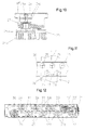
werden können, ist in den Fig.13 bis 16 ein drittes
Ausführungsbeispiel veranschaulicht, bei dem jeder Tellerbürste
25 ein gesonderter Antriebsmotor 34 zugeordnet
ist, wobei es vorgezogen wird, jeden Antriebsmotor
34 mit einer gesonderten Drehzahlregelung auszustatten.
Die einzelnen Tellerbürsten 25 können dabei an den nach
unten ragenden Enden der Motorantriebswellen 34a drehfest
angebracht sein, so daß die Tellerbürsten 25 dann
wiederum um vertikale Drehachsen rotierend angetrieben
werden können. Auch bei diesem dritten Ausführungsbeispiel
sind die Tellerbürsten 25 mit ihrem Einzelantriebsmotoren
34 in einem eigenen Werkzeug-Tragrahmen
19' aufgenommen und gehaltert, der in Formgebung und
Außenabmessungen denen des weiter oben anhand etwa der
Fig.7 - 10 beschriebenen Werkzeug Tragrahmen 19' entsprechen.While previously two typical with reference to FIGS. 7 to 10 and 12
Embodiments have been explained how
in the
Durch diese Verwendung von Einzelantriebsmotoren 34 für
die Tellerbürsten 25 ergeben sich vielfältige Variationsmöglichkeiten,
bei der Bearbeitung von verschiedenen
Werkstücken. So können die Tellerbürsten 25 alle mit
gleichartigen oder einzeln bzw. gruppenweise mit unterschiedlichen
Drehzahlen rotierend angetrieben werden.
Darüber hinaus kann es dabei vorteilhaft sein, wenn
diese Tellerbürsten 25 dann mit stufenlos einstellbaren
Drehzahlen rotierend angetrieben werden, wobei es auβerdem
auch noch von Vorteil sein kann, wenn diese Tellerbürsten
25 wahlweise in der einen oder anderen Drehrichtung
angetrieben werden können, und zwar alle Tellerbürsten
25 jeweils in der einen oder anderen Drehrichtung
oder einzelne oder gruppenweise einander entgegengerichtet.
Des weiteren besteht auch die Möglichkeit,
beispielsweise in Anpassung an die jeweilige
Werkstückbreite oder an mehrere nebeneinander angeordnete
Werkstücke, alle Bearbeitungswerkzeuge einzeln
oder gruppenweise anzusteuern und anzutreiben.Through this use of
Besonders bei der Verwendung von Einzelantriebsmotoren
34 für die Tellerbürsten 25, ggf. aber auch bei Verwendung
einer gemeinsamen Antriebseinrichtung für alle
Tellerbürsten 25, besteht auch die Möglichkeit, die
Tellerbürsten 25 einzeln, gruppenweise oder gemeinsam
gegen die Werkstück-Oberfläche 2a anzustellen. Dies ist
beispielsweise dann vorteilhaft, wenn der Borstenbesatz
25a der Tellerbürsten um ein gewisses Maß abgenutzt
ist, d.h. es besteht die Möglichkeit, die Tellerbürsten
25 entsprechend ihrer jeweiligen Abnutzung um ein angepaßtes
Maß nachzustellen.Especially when using
Zusammenfassend kann somit nochmals gesagt werden, daß
durch diese erfindungsgemäße Ausführung die Oberflächen
2a von Werkstücken 2 in ein und derselben Bearbeitungsvorrichtung
1 wahlweise mittels einer wenigstens eine
Bearbeitungswalze, vorzugsweise eine Bürstenwalze 6
enthaltenden ersten Werkzeugeinheit 5 oder - im Austausch
dazu - mittels einer eine Gruppe von tellerförmigen
Bearbeitungswerkzeugen, vorzugsweise Tellerbürsten
25 enthaltenden zweiten Werkzeugeinheit 30 bearbeitet
werden. Dabei wird dann in jeweils entsprechender
Weise die Bürstenwalze 6 etwa in ihrer radialen
Richtung gegen die Werkstück-Oberflächen 2a angestellt,
während die Tellerbürsten 25 etwa in ihrer axialen
Richtung gegen die Werkstück-Oberflächen 2a angestellt
werden, und zwar jeweils entsprechend dem Doppelpfeil 7
in den Fig.1 und 2. Die Werkstücke 2 werden dann während
der Bearbeitung ihrer Oberflächen 2a mit Hilfe der
Transporteinrichtung 3 in Längsrichtung unter den Bearbeitungswerkzeugen,
also der Bürstenwalze 6 oder unter
den Tellerbürsten 25 entlang transportiert. Dabei sind
dann die Werkstücke 2 hinreichend fest bzw. ortsfest
auf der Transporteinrichtung 3 abgelegt, wobei sie mit
Hilfe dieser Transporteinrichtung 3 je nach Bedarf kontinuierlich,
absatzweise oder reversierbar relativ zu
den Bearbeitungswerkzeugen transportiert werden.In summary it can be said again that
the surfaces according to this embodiment of the invention
2a of
Claims (27)
dadurch gekennzeichnet, daß die Werkstück-Oberflächen (2a) in wenigstens einer Bearbeitungszone derselben Bearbeitungsvorrichtung (1) wahlweise mittels einer wenigstens eine Bearbeitungswalze (6) enthaltenden ersten Werkzeugeinheit (5) oder einer eine Gruppe von tellerförmigen Bearbeitungswerkzeugen (25) enthaltenden zweiten Werkzeugeinheit (30) bearbeitet werden, wobei die Bearbeitungswalze (6) etwa in ihrer radialen Richtung und die tellerförmigen Bearbeitungswerkzeuge (25) etwa in ihrer axialen Richtung gegen die Werkstück-oberflächen (2a) angestellt werden.Method for machining surfaces of essentially flat workpieces in a machining device, wherein rotationally drivable machining tools are set against the surfaces of the workpieces to be machined and workpieces and tools are moved relative to one another during surface machining,
characterized in that the workpiece surfaces (2a) in at least one machining zone of the same machining device (1) optionally by means of a first tool unit (5) containing at least one machining roller (6) or a second tool unit (30) containing a group of plate-shaped machining tools (25) ) are processed, the processing roller (6) being set approximately in its radial direction and the plate-shaped processing tools (25) approximately in its axial direction against the workpiece surfaces (2a).
dadurch gekennzeichnet, daß für wenigstens eine Bearbeitungszone dieser Vorrichtung (1) eine wenigstens eine Bearbeitungswalze (6) enthaltende erste Werkzeugeinheit (5) und eine wenigstens eine Gruppe von tellerförmigen Bearbeitungswerkzeugen (25) enthaltende zweite Werkzeugeinheit (30) vorgesehen und diese Werkzeugeinheiten (5, 30) wahlweise zur Bearbeitung der Werkstück-oberflächen (2a) betreibbar sind, wobei die Bearbeitungswalze (6) mit ihrer Außenumfangsfläche in etwa radialer Richtung (7) und die tellerförmigen Bearbeitungswerkzeuge (25) mit ihren äußeren Stirnseiten in etwa axialer Richtung (7) gegen die Werkstück-Oberflächen anstellbar sind.Device for processing surfaces (2a) of essentially flat workpieces (2), with rotatingly drivable processing tools (6, 25) arranged in a main device frame (8), which can be set against the surfaces (2a) of the workpieces (2) to be processed are, workpieces and tools being movable relative to one another,
characterized in that for at least one processing zone of this device (1) there is provided a first tool unit (5) containing at least one processing roller (6) and a second tool unit (30) containing at least one group of plate-shaped processing tools (25), and these tool units (5, 30) can be operated optionally for machining the workpiece surfaces (2a), the machining roller (6) with its outer peripheral surface in approximately the radial direction (7) and the plate-shaped machining tools (25) with their outer end faces in approximately the axial direction (7) the workpiece surfaces are adjustable.
Priority Applications (1)
| Application Number | Priority Date | Filing Date | Title |
|---|---|---|---|
| DE20122200U DE20122200U1 (en) | 2000-07-24 | 2001-07-12 | Workpiece surface machining process involves machining surfaces with one tool unit containing machining roll and one tool unit containing plate-type tools |
Applications Claiming Priority (2)
| Application Number | Priority Date | Filing Date | Title |
|---|---|---|---|
| DE10035977A DE10035977A1 (en) | 2000-07-24 | 2000-07-24 | Method and device for machining workpiece surfaces |
| DE10035977 | 2000-07-24 |
Publications (2)
| Publication Number | Publication Date |
|---|---|
| EP1175961A2 true EP1175961A2 (en) | 2002-01-30 |
| EP1175961A3 EP1175961A3 (en) | 2003-12-17 |
Family
ID=7650013
Family Applications (1)
| Application Number | Title | Priority Date | Filing Date |
|---|---|---|---|
| EP01117029A Withdrawn EP1175961A3 (en) | 2000-07-24 | 2001-07-12 | Method and apparatus for machining workpiece surfaces |
Country Status (3)
| Country | Link |
|---|---|
| US (1) | US20020068515A1 (en) |
| EP (1) | EP1175961A3 (en) |
| DE (1) | DE10035977A1 (en) |
Cited By (10)
| Publication number | Priority date | Publication date | Assignee | Title |
|---|---|---|---|---|
| EP1384552A1 (en) * | 2002-07-26 | 2004-01-28 | DuBois Equipment Company, Inc. | Scuffing machine for finishing wood products |
| EP1477275A1 (en) * | 2003-05-12 | 2004-11-17 | Slipcon Holding International ApS | Abrading machine with abrading discs, which are moved in a reciprocatory movement transverse to the item |
| WO2004098831A1 (en) * | 2003-05-12 | 2004-11-18 | Slipcon Holding International Aps | Abrading machine with abrading discs, which are moved in a reciprocatory movement transverse to the item |
| WO2007095947A1 (en) * | 2006-02-22 | 2007-08-30 | Amanda Patent & Licensing Sia | A brush module |
| EP2796242A3 (en) * | 2013-04-22 | 2014-11-26 | Arku Maschinenbau GmbH | Machine for deburring and method for configuring same |
| ITRM20130453A1 (en) * | 2013-08-01 | 2015-02-02 | Scm Group Spa | FURNISHED ROTARY DISC MACHINING EQUIPMENT AND RELATED PROCESSING MODULE. |
| DK178121B1 (en) * | 2014-06-20 | 2015-06-01 | Flex Trim As | Grinding machine with grinding heads on at least two movable slides |
| WO2016000819A1 (en) * | 2014-07-01 | 2016-01-07 | Karl Heesemann Maschinenfabrik Gmbh & Co. Kg | Grinding machine for grinding a surface of a workpiece |
| CN113167346A (en) * | 2019-01-11 | 2021-07-23 | 大陆-特韦斯贸易合伙股份公司及两合公司 | Can-shaped composite brake disc for a motor vehicle |
| EP3928923A1 (en) * | 2020-06-16 | 2021-12-29 | Schindler GmbH | Method for the treatment of the surface of a rock and / or concrete surface |
Families Citing this family (12)
| Publication number | Priority date | Publication date | Assignee | Title |
|---|---|---|---|---|
| DK200301826A (en) * | 2003-12-10 | 2005-06-11 | Flex Trim As | Abrasive device for treating a surface |
| DE202005006412U1 (en) * | 2004-05-27 | 2005-06-30 | Battenfeld Extrusionstechnik Gmbh | cooler |
| DE102007031656A1 (en) * | 2007-07-06 | 2009-01-08 | Heesemann, Jürgen, Dipl.-Ing. | grinding machine |
| DE102010026903A1 (en) | 2010-07-12 | 2012-01-12 | Amw Gmbh | Transdermal therapeutic system with avocado oil or palm oil as adjuvant |
| CN102179762B (en) * | 2011-04-06 | 2013-03-27 | 浙江金圣竹木有限公司 | Chopping board polishing machine |
| CN102581714B (en) * | 2012-03-06 | 2014-01-15 | 珠海镇东有限公司 | Automatic trimming and brushing device of scrubbing machine |
| ES2600755B1 (en) * | 2015-08-10 | 2018-03-02 | Calvet Brothers, S.L. | STEEL FILAMENT, POLISHING BRUSH THAT INCLUDES THE SAME AND POLISHING DEVICE THAT INCLUDES A PLURLITY OF POLISHING BRUSHES AND USE OF THE SAME |
| DE102015010612A1 (en) * | 2015-08-18 | 2017-02-23 | Wöhler Brush Tech GmbH | Apparatus and method of surface treatment of workpieces |
| IT201900024631A1 (en) * | 2019-12-19 | 2021-06-19 | Biesse Spa | DEBURRING MACHINE FOR FINISHING ELEMENTS OF WOOD, METAL, PLASTIC MATERIAL OR SIMILAR |
| CN112775756B (en) * | 2021-01-28 | 2022-07-29 | 中国核动力研究设计院 | Grinding device in bushing hole of electric heating element of voltage stabilizer |
| CN113275962B (en) * | 2021-06-16 | 2022-10-25 | 江西和美陶瓷有限公司 | Pretreatment device for ceramic tile water absorption rate detection sample and control method thereof |
| CN117226442A (en) * | 2023-11-01 | 2023-12-15 | 东莞市彼联机械科技有限公司 | Numerical control equipment for workpiece correction |
Citations (4)
| Publication number | Priority date | Publication date | Assignee | Title |
|---|---|---|---|---|
| US2635653A (en) * | 1950-07-27 | 1953-04-21 | Charles H Hennell | Apparatus for embossing graining of wood |
| DE2304439A1 (en) * | 1973-01-30 | 1974-08-01 | Rosner Ohg L | DEVICE FOR BRUSHING THE PROFILE OF A WOODEN SURFACE |
| DE2657069A1 (en) * | 1976-12-03 | 1978-06-22 | Mitsubishi Heavy Ind Ltd | METHOD AND DEVICE FOR ROUNDING EDGES |
| US5105583A (en) * | 1990-08-29 | 1992-04-21 | Hammond Machinery Inc. | Workpiece deburring method and apparatus |
Family Cites Families (2)
| Publication number | Priority date | Publication date | Assignee | Title |
|---|---|---|---|---|
| US2989823A (en) * | 1959-03-09 | 1961-06-27 | Merit Products Inc | Finishing machine with reciprocative rotary finishing roll |
| NL7904403A (en) * | 1979-06-05 | 1980-12-09 | Linden Bv Machine | APPARATUS FOR SURFACE PROCESSING OF OBJECTS. |
-
2000
- 2000-07-24 DE DE10035977A patent/DE10035977A1/en not_active Withdrawn
-
2001
- 2001-07-12 EP EP01117029A patent/EP1175961A3/en not_active Withdrawn
- 2001-07-21 US US09/909,749 patent/US20020068515A1/en not_active Abandoned
Patent Citations (4)
| Publication number | Priority date | Publication date | Assignee | Title |
|---|---|---|---|---|
| US2635653A (en) * | 1950-07-27 | 1953-04-21 | Charles H Hennell | Apparatus for embossing graining of wood |
| DE2304439A1 (en) * | 1973-01-30 | 1974-08-01 | Rosner Ohg L | DEVICE FOR BRUSHING THE PROFILE OF A WOODEN SURFACE |
| DE2657069A1 (en) * | 1976-12-03 | 1978-06-22 | Mitsubishi Heavy Ind Ltd | METHOD AND DEVICE FOR ROUNDING EDGES |
| US5105583A (en) * | 1990-08-29 | 1992-04-21 | Hammond Machinery Inc. | Workpiece deburring method and apparatus |
Cited By (14)
| Publication number | Priority date | Publication date | Assignee | Title |
|---|---|---|---|---|
| EP1384552A1 (en) * | 2002-07-26 | 2004-01-28 | DuBois Equipment Company, Inc. | Scuffing machine for finishing wood products |
| DK178219B1 (en) * | 2003-05-12 | 2015-08-31 | Slipcon Holding Internat Aps | Rotary abrasive grinder moving in a reciprocating movement across the workpiece |
| EP1477275A1 (en) * | 2003-05-12 | 2004-11-17 | Slipcon Holding International ApS | Abrading machine with abrading discs, which are moved in a reciprocatory movement transverse to the item |
| WO2004098831A1 (en) * | 2003-05-12 | 2004-11-18 | Slipcon Holding International Aps | Abrading machine with abrading discs, which are moved in a reciprocatory movement transverse to the item |
| WO2007095947A1 (en) * | 2006-02-22 | 2007-08-30 | Amanda Patent & Licensing Sia | A brush module |
| EP2796242A3 (en) * | 2013-04-22 | 2014-11-26 | Arku Maschinenbau GmbH | Machine for deburring and method for configuring same |
| ITRM20130453A1 (en) * | 2013-08-01 | 2015-02-02 | Scm Group Spa | FURNISHED ROTARY DISC MACHINING EQUIPMENT AND RELATED PROCESSING MODULE. |
| DK178121B1 (en) * | 2014-06-20 | 2015-06-01 | Flex Trim As | Grinding machine with grinding heads on at least two movable slides |
| WO2016000819A1 (en) * | 2014-07-01 | 2016-01-07 | Karl Heesemann Maschinenfabrik Gmbh & Co. Kg | Grinding machine for grinding a surface of a workpiece |
| DE102014009582A1 (en) | 2014-07-01 | 2016-01-07 | Karl Heesemann Maschinenfabrik Gmbh & Co Kg | Grinding machine for grinding a surface of a workpiece |
| CN113167346A (en) * | 2019-01-11 | 2021-07-23 | 大陆-特韦斯贸易合伙股份公司及两合公司 | Can-shaped composite brake disc for a motor vehicle |
| US11885384B2 (en) | 2019-01-11 | 2024-01-30 | Continental Teves Ag & Co. Ohg | Pot-shaped composite brake rotor for motor vehicles |
| CN113167346B (en) * | 2019-01-11 | 2024-03-08 | 大陆汽车科技有限公司 | Pot-shaped composite brake disc for motor vehicles |
| EP3928923A1 (en) * | 2020-06-16 | 2021-12-29 | Schindler GmbH | Method for the treatment of the surface of a rock and / or concrete surface |
Also Published As
| Publication number | Publication date |
|---|---|
| DE10035977A1 (en) | 2002-02-07 |
| EP1175961A3 (en) | 2003-12-17 |
| US20020068515A1 (en) | 2002-06-06 |
Similar Documents
| Publication | Publication Date | Title |
|---|---|---|
| EP1175961A2 (en) | Method and apparatus for machining workpiece surfaces | |
| DE3416664C2 (en) | Device for controlling the cutting speed of the saw blade of a band saw machine | |
| EP1068917A2 (en) | Device and method for machining crankpins | |
| DE1479627B2 (en) | MACHINE FOR PROCESSING, PREFERABLY WELDING AND SEPARATING A DOUBLE LINE, IN PARTICULAR A THERMOPLASTIC FILM, WHEN MANUFACTURING BAGS | |
| DE2311011A1 (en) | COPY GRINDING MACHINE FOR WORKPIECES MADE OF WOOD OR PLASTIC WITH IRREGULAR BODY SHAPES | |
| DE60304179T2 (en) | grinding machine | |
| DE19723306C2 (en) | Method and device for grinding or polishing end faces of plate-shaped bodies | |
| DE3416629C3 (en) | ||
| EP1314513A2 (en) | Apparatus for trimming of glass plates | |
| DE19808804C2 (en) | Machine for surface processing at least one textile web, in particular for roughening and / or sanding or the like. | |
| DE19821982C2 (en) | Profile belt grinder | |
| DE2151218A1 (en) | Method and device for punching windows in blanks made of sheet material | |
| DE2614843C2 (en) | Copy grinder | |
| DE20122200U1 (en) | Workpiece surface machining process involves machining surfaces with one tool unit containing machining roll and one tool unit containing plate-type tools | |
| DE2551804C3 (en) | Device for chamfering or sharpening of workpieces, each consisting of a cylindrical shaft with a head | |
| DE3626964A1 (en) | Circular shears | |
| DE3430065C2 (en) | Deburring machine for the end machining of cylindrical workpieces such as tubes, rods or the like | |
| DE4000251A1 (en) | Grinding surface of wire or bar - involves rotating disc with groups of rollers to guide abrasive belt | |
| DE2403574C2 (en) | Lapping machine | |
| DE3535636A1 (en) | Transportable grinding device | |
| DE2846238A1 (en) | Automatic wood brushing machine - has motor-driven rotary brushes in frame moving along guide tracks over wood surface | |
| EP0629476B1 (en) | Machine for working wooden, plastic or similar work pieces | |
| DE7406370U (en) | GRINDING MACHINE FOR THE APPLICATION OF DECORATION GRINDING TO HOLLOW AND PRESSED GLASSES | |
| DE19650851A1 (en) | Device for treating spines of stacked sheets to be bound into books, periodicals, etc. | |
| DE102021105394A1 (en) | Unit for deburring and rounding edges in a surface grinding machine |
Legal Events
| Date | Code | Title | Description |
|---|---|---|---|
| PUAI | Public reference made under article 153(3) epc to a published international application that has entered the european phase |
Free format text: ORIGINAL CODE: 0009012 |
|
| AK | Designated contracting states |
Kind code of ref document: A2 Designated state(s): AT BE CH CY DE DK ES FI FR GB GR IE IT LI LU MC NL PT SE TR |
|
| AX | Request for extension of the european patent |
Free format text: AL;LT;LV;MK;RO;SI |
|
| PUAL | Search report despatched |
Free format text: ORIGINAL CODE: 0009013 |
|
| AK | Designated contracting states |
Kind code of ref document: A3 Designated state(s): AT BE CH CY DE DK ES FI FR GB GR IE IT LI LU MC NL PT SE TR |
|
| AX | Request for extension of the european patent |
Extension state: AL LT LV MK RO SI |
|
| AKX | Designation fees paid | ||
| REG | Reference to a national code |
Ref country code: DE Ref legal event code: 8566 |
|
| STAA | Information on the status of an ep patent application or granted ep patent |
Free format text: STATUS: THE APPLICATION IS DEEMED TO BE WITHDRAWN |
|
| 18D | Application deemed to be withdrawn |
Effective date: 20040618 |