EP1175832A2 - Improvements in fodder distribution conveyors - Google Patents
Improvements in fodder distribution conveyors Download PDFInfo
- Publication number
- EP1175832A2 EP1175832A2 EP01500188A EP01500188A EP1175832A2 EP 1175832 A2 EP1175832 A2 EP 1175832A2 EP 01500188 A EP01500188 A EP 01500188A EP 01500188 A EP01500188 A EP 01500188A EP 1175832 A2 EP1175832 A2 EP 1175832A2
- Authority
- EP
- European Patent Office
- Prior art keywords
- fodder
- cable
- chain
- tooth
- teeth
- Prior art date
- Legal status (The legal status is an assumption and is not a legal conclusion. Google has not performed a legal analysis and makes no representation as to the accuracy of the status listed.)
- Granted
Links
Images


Classifications
-
- A—HUMAN NECESSITIES
- A01—AGRICULTURE; FORESTRY; ANIMAL HUSBANDRY; HUNTING; TRAPPING; FISHING
- A01K—ANIMAL HUSBANDRY; AVICULTURE; APICULTURE; PISCICULTURE; FISHING; REARING OR BREEDING ANIMALS, NOT OTHERWISE PROVIDED FOR; NEW BREEDS OF ANIMALS
- A01K39/00—Feeding or drinking appliances for poultry or other birds
- A01K39/01—Feeding devices
-
- A—HUMAN NECESSITIES
- A01—AGRICULTURE; FORESTRY; ANIMAL HUSBANDRY; HUNTING; TRAPPING; FISHING
- A01K—ANIMAL HUSBANDRY; AVICULTURE; APICULTURE; PISCICULTURE; FISHING; REARING OR BREEDING ANIMALS, NOT OTHERWISE PROVIDED FOR; NEW BREEDS OF ANIMALS
- A01K5/00—Feeding devices for stock or game ; Feeding wagons; Feeding stacks
- A01K5/02—Automatic devices
- A01K5/0258—Automatic devices with endless screws
Definitions
- the present invention refers to some improvements in fodder distribution conveyors, which can be used in a great variety of farms with stabled animals, in order to automate the distribution of food.
- Fodder distribution conveyors which in general are equipped with an endless cable, or endless chain, are already known. Both the chain and the cable have a plurality of transverse dragging means, also called disks or scrapers, which move along a channel or a pipe, with outlets for the unloading of a portion of fodder into other pipes, or similar, which carry the respective fodder portions to a respective device for their sharing-out into cells, or else the unloading is carried out directly in the latter.
- These fodder unloading areas to the corresponding cell are called receiving stations.
- the chain or the cable In the known conveyors, the chain or the cable, with their transverse dragging means, move according to a closed path which extends from a fodder entry station and passes by the receiving stations in which the product is unloaded through the pipe outlets, or, where appropriate, the channel.
- the movement of the cable or chain is obtained by means of a driving wheel.
- the type of driving wheel equipped with a single-piece peripheral toothing, between whose teeth engage the disks fixed to the cable or chain as the wheel turns.
- Fodder distribution conveyors equipped with the improvements object of the invention are of the type which have an endless cable or chain, with a plurality of transverse dragging means and which move along a conduit, with outlets for the unloading of corresponding portions of fodder, the cable or chain moving, thanks to a driving wheel provided with a peripheral toothing, between whose teeth the transverse dragging means engages.
- the driving wheel is made up of a disk joined to a driving means and by a series of replaceable teeth, mounted around its periphery; and in that each tooth is made up of two parts determining an upper longitudinal axis channel solely for the passage of the cable or the chain.
- each tooth is mounted in a tilting fashion on the driving wheel disk and in that in its interior it has an elastic means.
- each tooth has a conical face and another flat, against one of which the respective transverse dragging means of the rear face, conical or flat, can abut.
- Figure 1 shows a diagrammatic elevation view of a fodder distribution conveyor installed on a farm of stabled animals, such as pigs, for example.
- Figure 2 corresponds to a perspective view of a driving wheel according to the invention and provided with 15 teeth.
- Figures 3 and 4 show the two parts which, once juxtaposed and joined to each other and to the disk, make up one of the teeth which, in a suitable number, form part of the driving wheel.
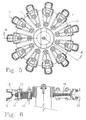
- Figure 5 is an elevation view of a driving wheel according to the invention provided with 11 teeth.
- Figure 6 is a section view according to 6-6 of Figure 5.
- the installation shown diagrammatically in Figure 1 is conventional and corresponds to a farm of stabled animals. It is composed of a conveyor marked, in general, by -1-, for the distribution of fodder -2-, stored in the deposit -3-, the conveyor showing a pipe -4- within which the collection, movement and distribution is carried out.
- the arrows -F1 to F4- show the direction of the endless cable's circuit along the pipe interior.
- the conveyor comprises a drive unit -6- of the cable 5 provided with transverse disks -7-, equidistant and fixed to the same.
- Unit -6- is composed of a driving wheel -8-, toothed on its periphery and joined by its shaft to an electromotor with a reducer (not shown), and there must be a practical similarity between the pitch of the teeth of wheel -8- and the pitch of the disks -7- of cable -5- in order to ensure that the latter insert properly into the teeth, in other words, so that they abut on their rear face onto the front face of the teeth.
- Unit -6- also comprises another wheel -9- which performs a tensile function in order to achieve a certain mechanical tension in cable -5-, which, in practice, can be regulated and this unit is normally situated in a protective box.
- the fodder portions are transported until they pass above the pipes -11- and -12- as will be explained later (obviously the pipes will be much greater in number in practice, only two have been shown to facilitate understanding and the drawing). There are some lower outlets in pipe -4- in order to make possible the unloading of corresponding fodder portions to the interior of the pipes -11- and -12- .
- These pipes (variable in number according to the allocation) lead into respective deposits of troughs -13- and -14- which are to be found in each compartment or cell with animals for their feeding, including a drinking trough.
- the fodder unloading areas constitute what was previously called fodder receiving stations.
- the fodder distribution conveyor is suitably developed for the system in which it is located. So, for example, it is arranged zigzag, covering the feeding trays/troughs that it has to feed during its enclosed course.
- the improvements in the fodder distribution conveyors of the type described present (figure 2) a driving wheel -15- made up of a disk -16-, which is joined to a motor, where appropriate, with a reducer (not shown).
- a driving wheel -15- made up of a disk -16-, which is joined to a motor, where appropriate, with a reducer (not shown).
- Around the periphery of the disk teeth -17- are fitted, each being fitted to the disk by means of two screws -T1 - and -T2-(figures 5 and 6), so that they are detachable and replaceable.
- Each tooth is made up of two parts -18- and -19- (figures 2, 3, 4 and 6) which are joined to each other and are fixed to the disk as shown, determining a channel -20- (figures 2 and 6) at its free end, permitting the passage of cable -5- or the chain, but not of transverse disks -7-.
- the channel is situated according to a longitudinal geometric shaft, in other words, like a circumference situated on a perpendicular plane to the motor shaft to which the disk is fitted.
- teeth -17- are fitted tilting onto the disk -15- of the driving wheel by means of, for example, a dimensioned and/or configuration of the end holes with the screws -T1- in the teeth, which facilitates its tilting and screw -T2- working as a turning shaft.
- an elastic means -21- (figure 6) acting, to a certain degree, as a cushion and tensor.
- the elastic means is situated in a specific space between the two parts -18- and -19- of each tooth (figures 3 and 4) being joined to each other and is partly delimited by two projections -22- and -23- and by two sleeves -24- and -25- (these show each orifice for the passage of a screw-T2-, whilst the holes -25- and -27- allow the passing of a screw -T1-).
- each tooth will have a conical face -28- and another flat (not shown).
- each tooth will have a conical face -28- and another flat (not shown).
Landscapes
- Life Sciences & Earth Sciences (AREA)
- Environmental Sciences (AREA)
- Birds (AREA)
- Animal Husbandry (AREA)
- Biodiversity & Conservation Biology (AREA)
- Pusher Or Impeller Conveyors (AREA)
Abstract
Description
Claims (3)
- Improvements in fodder distribution conveyors, of the type which have an endless cable or chain, with a plurality of transverse dragging means and which move along a conduit which has corresponding outlets for the unloading of corresponding portions of fodder into respective conduits which drive them towards a farm's cell, the cable or chain being moved with their transverse dragging means by a driving motor provided with peripheral toothing, between whose teeth the transverse dragging means engages; characterized in that the driving wheel is made up of a disk joined to a motor means and a series of replaceable teeth, mounted around its periphery; and in that each tooth is composed of two parts determining an upper longitudinal axis channel solely for the passing of the cable or chain.
- Improvements in fodder distribution conveyors, according to the 1st claim, characterized in that, especially, each tooth is mounted in a tilting fashion on the driving wheel disk and in its interior has an elastic means.
- Improvements in fodder distribution conveyors, according to the 1st claim, characterized in that each tooth has a conical face and another flat, against one of which the respective transverse dragging means of the rear face, conical or flat, can abut.
Applications Claiming Priority (2)
| Application Number | Priority Date | Filing Date | Title |
|---|---|---|---|
| ES200001869 | 2000-07-26 | ||
| ES200001869A ES2165333B1 (en) | 2000-07-26 | 2000-07-26 | IMPROVEMENTS IN THE CONVEYORS FOR THE DISTRIBUTION OF FEED. |
Publications (3)
| Publication Number | Publication Date |
|---|---|
| EP1175832A2 true EP1175832A2 (en) | 2002-01-30 |
| EP1175832A3 EP1175832A3 (en) | 2002-07-24 |
| EP1175832B1 EP1175832B1 (en) | 2004-04-14 |
Family
ID=8494431
Family Applications (1)
| Application Number | Title | Priority Date | Filing Date |
|---|---|---|---|
| EP01500188A Expired - Lifetime EP1175832B1 (en) | 2000-07-26 | 2001-07-17 | Improvements in fodder distribution conveyors |
Country Status (6)
| Country | Link |
|---|---|
| US (1) | US6581756B2 (en) |
| EP (1) | EP1175832B1 (en) |
| CA (1) | CA2353781A1 (en) |
| DE (1) | DE60102753T2 (en) |
| DK (1) | DK1175832T3 (en) |
| ES (2) | ES2165333B1 (en) |
Cited By (2)
| Publication number | Priority date | Publication date | Assignee | Title |
|---|---|---|---|---|
| EP3626054A1 (en) * | 2018-09-19 | 2020-03-25 | Big Dutchman International GmbH | Drive wheel for driving a feed chain for dry feeding of commercial animals |
| FR3103996A1 (en) | 2019-12-09 | 2021-06-11 | Pellenc | Vibrating double comb comb head and harvesting tool provided with such a comb head |
Families Citing this family (4)
| Publication number | Priority date | Publication date | Assignee | Title |
|---|---|---|---|---|
| WO2006087774A1 (en) * | 2005-02-16 | 2006-08-24 | Kabushiki Kaisha Fujii Shoukai | Feed conveyance device |
| NL2017134B1 (en) * | 2016-07-08 | 2018-01-15 | Romariës B V | Chain wheel |
| CN110410481B (en) * | 2019-09-04 | 2024-11-01 | 沧州市永高农牧机械科技有限公司 | Elastic reset gear tooth driving wheel |
| CN111631157A (en) * | 2020-07-07 | 2020-09-08 | 河南省恒辉农牧设备有限公司 | Mainframe box for feeding system |
Family Cites Families (17)
| Publication number | Priority date | Publication date | Assignee | Title |
|---|---|---|---|---|
| DE7530444U (en) * | 1976-01-29 | Pohlig-Heckel-Bleichert Vereinigte Maschinenfabriken Ag, 5000 Koeln | Chain rear wheel | |
| US1704150A (en) * | 1927-03-03 | 1929-03-05 | Ralph J Riley | Sprocket wheel |
| US2333926A (en) * | 1941-01-25 | 1943-11-09 | Henry W Hapman | Conveyer |
| US3905473A (en) * | 1974-01-21 | 1975-09-16 | Intraco | Drive apparatus |
| US3899219A (en) * | 1974-05-28 | 1975-08-12 | Caterpillar Tractor Co | Self-cleaning sprocket means |
| DE2606076A1 (en) * | 1976-02-16 | 1977-08-25 | Pohlig Heckel Bleichert | CHAIN CUP |
| US4195725A (en) * | 1978-05-18 | 1980-04-01 | Intraco, Inc. | Drive unit for cable conveyor |
| US4257519A (en) * | 1979-05-03 | 1981-03-24 | Leach John M | Frictionless entry and release sprocket |
| US4308019A (en) * | 1980-02-07 | 1981-12-29 | Industrial Chain Products, Inc. | Drag chain sprocket |
| GB2093148A (en) * | 1981-02-13 | 1982-08-25 | Tyso Gareth | Toothed rotary drive- transmitting members with replaceable teeth |
| DK432481A (en) * | 1981-09-30 | 1983-03-31 | Christian Thomsen Dahl | ROAD TRANSPORTATION TRAIL STATION |
| US4752281A (en) * | 1986-11-05 | 1988-06-21 | Caterpillar Inc. | Isolated tooth drive sprocket assembly |
| AT401413B (en) * | 1987-11-04 | 1996-09-25 | Pengg Walenta Ketten | SPROCKET FOR ROUND STEEL CHAINS |
| JP2516075B2 (en) * | 1989-11-30 | 1996-07-10 | 日立金属株式会社 | Replacement tooth sprocket wheel |
| US5203861A (en) * | 1991-12-18 | 1993-04-20 | Irwin Guy L | Plastic sprocket wheel with replaceable teeth |
| DE9307939U1 (en) * | 1992-11-26 | 1994-06-01 | Pwh Anlagen + Systeme Gmbh, 66386 St Ingbert | Self-adjusting sprocket |
| US6090003A (en) * | 1996-07-25 | 2000-07-18 | Cloyes Gear & Products, Inc. | Random engagement roller chain sprocket having improved noise characteristics |
-
2000
- 2000-07-26 ES ES200001869A patent/ES2165333B1/en not_active Expired - Fee Related
-
2001
- 2001-07-12 US US09/902,585 patent/US6581756B2/en not_active Expired - Fee Related
- 2001-07-17 EP EP01500188A patent/EP1175832B1/en not_active Expired - Lifetime
- 2001-07-17 DK DK01500188T patent/DK1175832T3/en active
- 2001-07-17 ES ES01500188T patent/ES2215871T3/en not_active Expired - Lifetime
- 2001-07-17 DE DE60102753T patent/DE60102753T2/en not_active Expired - Lifetime
- 2001-07-25 CA CA002353781A patent/CA2353781A1/en not_active Abandoned
Cited By (6)
| Publication number | Priority date | Publication date | Assignee | Title |
|---|---|---|---|---|
| EP3626054A1 (en) * | 2018-09-19 | 2020-03-25 | Big Dutchman International GmbH | Drive wheel for driving a feed chain for dry feeding of commercial animals |
| EP3626054B1 (en) | 2018-09-19 | 2021-06-23 | Big Dutchman International GmbH | Drive wheel for driving a feed chain for dry feeding of commercial animals |
| EP3939419A1 (en) * | 2018-09-19 | 2022-01-19 | Big Dutchman International GmbH | Drive wheel for driving a feed chain for dry feeding of commercial animals |
| US11254509B2 (en) | 2018-09-19 | 2022-02-22 | Big Dutchman International Gmbh | Drive wheel for driving a feed chain for the dry feeding of livestock |
| FR3103996A1 (en) | 2019-12-09 | 2021-06-11 | Pellenc | Vibrating double comb comb head and harvesting tool provided with such a comb head |
| EP3834600A1 (en) | 2019-12-09 | 2021-06-16 | Pellenc | Rake head with double vibrating rake and harvesting tool provided with such a rake head |
Also Published As
| Publication number | Publication date |
|---|---|
| US20020014393A1 (en) | 2002-02-07 |
| ES2165333B1 (en) | 2003-06-16 |
| US6581756B2 (en) | 2003-06-24 |
| CA2353781A1 (en) | 2002-01-26 |
| DE60102753T2 (en) | 2005-03-31 |
| ES2165333A1 (en) | 2002-03-01 |
| EP1175832A3 (en) | 2002-07-24 |
| ES2215871T3 (en) | 2004-10-16 |
| DK1175832T3 (en) | 2004-08-16 |
| DE60102753D1 (en) | 2004-05-19 |
| EP1175832B1 (en) | 2004-04-14 |
Similar Documents
| Publication | Publication Date | Title |
|---|---|---|
| AU2007200665B9 (en) | Dual belt drive for an agricultural header | |
| CA2561029C (en) | Conveyor feeder house chain slat | |
| US4230222A (en) | Grain conveyor assembly | |
| US6581756B2 (en) | Fodder distribution conveyors | |
| MXPA02005244A (en) | Conveyor system for can end conversion systems. | |
| EP0759270B1 (en) | Feed conveyor | |
| US3672334A (en) | Apparatus for distributing animal feed | |
| US11254509B2 (en) | Drive wheel for driving a feed chain for the dry feeding of livestock | |
| US4545716A (en) | Hay bale feeder | |
| EP0089362B1 (en) | A scraping conveyor | |
| US8074791B1 (en) | Hook assembly for a conveyor belt | |
| EP0060009B1 (en) | A conveyor system | |
| KR20060044384A (en) | Powder discharging device | |
| JP3771303B2 (en) | Shape-retaining roller device for pipe conveyors | |
| US3055485A (en) | Conveyor system for animal husbandry | |
| US2640462A (en) | Automatic poultry feeder | |
| US4381733A (en) | Livestock feed conveyor including cable clamp | |
| US4863420A (en) | Vehicular track drive assembly | |
| US2797001A (en) | Vehicle mounted apparatus for handling cut forage | |
| WO2000025576A1 (en) | Plant for allocation of materials like straw and silage and method for using such a plant | |
| CA2573086A1 (en) | A grain and fertiliser conveyer | |
| US3348660A (en) | Conveyors | |
| US20120085624A1 (en) | Toothed belt drive system for augers | |
| KR100509695B1 (en) | Straw Delivering Devices of Combine | |
| CN1016754B (en) | Equipment for keeping small animals |
Legal Events
| Date | Code | Title | Description |
|---|---|---|---|
| PUAI | Public reference made under article 153(3) epc to a published international application that has entered the european phase |
Free format text: ORIGINAL CODE: 0009012 |
|
| AK | Designated contracting states |
Kind code of ref document: A2 Designated state(s): AT BE CH CY DE DK ES FI FR GB GR IE IT LI LU MC NL PT SE TR |
|
| AX | Request for extension of the european patent |
Free format text: AL;LT;LV;MK;RO;SI |
|
| PUAL | Search report despatched |
Free format text: ORIGINAL CODE: 0009013 |
|
| AK | Designated contracting states |
Kind code of ref document: A3 Designated state(s): AT BE CH CY DE DK ES FI FR GB GR IE IT LI LU MC NL PT SE TR |
|
| AX | Request for extension of the european patent |
Free format text: AL;LT;LV;MK;RO;SI |
|
| 17P | Request for examination filed |
Effective date: 20030115 |
|
| AKX | Designation fees paid |
Designated state(s): DE DK ES FR IT NL |
|
| 17Q | First examination report despatched |
Effective date: 20030417 |
|
| GRAP | Despatch of communication of intention to grant a patent |
Free format text: ORIGINAL CODE: EPIDOSNIGR1 |
|
| GRAS | Grant fee paid |
Free format text: ORIGINAL CODE: EPIDOSNIGR3 |
|
| GRAA | (expected) grant |
Free format text: ORIGINAL CODE: 0009210 |
|
| AK | Designated contracting states |
Kind code of ref document: B1 Designated state(s): DE DK ES FR IT NL |
|
| REF | Corresponds to: |
Ref document number: 60102753 Country of ref document: DE Date of ref document: 20040519 Kind code of ref document: P |
|
| REG | Reference to a national code |
Ref country code: IE Ref legal event code: FG4D |
|
| REG | Reference to a national code |
Ref country code: DK Ref legal event code: T3 |
|
| REG | Reference to a national code |
Ref country code: ES Ref legal event code: FG2A Ref document number: 2215871 Country of ref document: ES Kind code of ref document: T3 |
|
| ET | Fr: translation filed | ||
| PLBE | No opposition filed within time limit |
Free format text: ORIGINAL CODE: 0009261 |
|
| STAA | Information on the status of an ep patent application or granted ep patent |
Free format text: STATUS: NO OPPOSITION FILED WITHIN TIME LIMIT |
|
| 26N | No opposition filed |
Effective date: 20050117 |
|
| REG | Reference to a national code |
Ref country code: IE Ref legal event code: MM4A |
|
| PGFP | Annual fee paid to national office [announced via postgrant information from national office to epo] |
Ref country code: NL Payment date: 20070731 Year of fee payment: 7 |
|
| PGFP | Annual fee paid to national office [announced via postgrant information from national office to epo] |
Ref country code: FR Payment date: 20070607 Year of fee payment: 7 |
|
| NLV4 | Nl: lapsed or anulled due to non-payment of the annual fee |
Effective date: 20090201 |
|
| REG | Reference to a national code |
Ref country code: FR Ref legal event code: ST Effective date: 20090331 |
|
| PG25 | Lapsed in a contracting state [announced via postgrant information from national office to epo] |
Ref country code: NL Free format text: LAPSE BECAUSE OF NON-PAYMENT OF DUE FEES Effective date: 20090201 |
|
| PG25 | Lapsed in a contracting state [announced via postgrant information from national office to epo] |
Ref country code: FR Free format text: LAPSE BECAUSE OF NON-PAYMENT OF DUE FEES Effective date: 20080731 |
|
| PGFP | Annual fee paid to national office [announced via postgrant information from national office to epo] |
Ref country code: DK Payment date: 20100607 Year of fee payment: 10 |
|
| PGFP | Annual fee paid to national office [announced via postgrant information from national office to epo] |
Ref country code: ES Payment date: 20100713 Year of fee payment: 10 |
|
| PGFP | Annual fee paid to national office [announced via postgrant information from national office to epo] |
Ref country code: DE Payment date: 20100723 Year of fee payment: 10 |
|
| PG25 | Lapsed in a contracting state [announced via postgrant information from national office to epo] |
Ref country code: IT Free format text: LAPSE BECAUSE OF NON-PAYMENT OF DUE FEES Effective date: 20090717 |
|
| PGFP | Annual fee paid to national office [announced via postgrant information from national office to epo] |
Ref country code: IT Payment date: 20100729 Year of fee payment: 10 |
|
| PGRI | Patent reinstated in contracting state [announced from national office to epo] |
Ref country code: IT Effective date: 20110616 |
|
| REG | Reference to a national code |
Ref country code: DK Ref legal event code: EBP |
|
| PG25 | Lapsed in a contracting state [announced via postgrant information from national office to epo] |
Ref country code: DE Free format text: LAPSE BECAUSE OF NON-PAYMENT OF DUE FEES Effective date: 20120201 |
|
| REG | Reference to a national code |
Ref country code: DE Ref legal event code: R119 Ref document number: 60102753 Country of ref document: DE Effective date: 20120201 |
|
| PG25 | Lapsed in a contracting state [announced via postgrant information from national office to epo] |
Ref country code: IT Free format text: LAPSE BECAUSE OF NON-PAYMENT OF DUE FEES Effective date: 20110717 |
|
| PG25 | Lapsed in a contracting state [announced via postgrant information from national office to epo] |
Ref country code: DK Free format text: LAPSE BECAUSE OF NON-PAYMENT OF DUE FEES Effective date: 20110731 |
|
| REG | Reference to a national code |
Ref country code: ES Ref legal event code: FD2A Effective date: 20130610 |
|
| PG25 | Lapsed in a contracting state [announced via postgrant information from national office to epo] |
Ref country code: ES Free format text: LAPSE BECAUSE OF NON-PAYMENT OF DUE FEES Effective date: 20110718 |