EP1175354B1 - Tablet dispenser - Google Patents
Tablet dispenser Download PDFInfo
- Publication number
- EP1175354B1 EP1175354B1 EP00925487A EP00925487A EP1175354B1 EP 1175354 B1 EP1175354 B1 EP 1175354B1 EP 00925487 A EP00925487 A EP 00925487A EP 00925487 A EP00925487 A EP 00925487A EP 1175354 B1 EP1175354 B1 EP 1175354B1
- Authority
- EP
- European Patent Office
- Prior art keywords
- lid portion
- body portion
- dispenser
- projections
- tabs
- Prior art date
- Legal status (The legal status is an assumption and is not a legal conclusion. Google has not performed a legal analysis and makes no representation as to the accuracy of the status listed.)
- Expired - Lifetime
Links
Images


Classifications
-
- B—PERFORMING OPERATIONS; TRANSPORTING
- B65—CONVEYING; PACKING; STORING; HANDLING THIN OR FILAMENTARY MATERIAL
- B65D—CONTAINERS FOR STORAGE OR TRANSPORT OF ARTICLES OR MATERIALS, e.g. BAGS, BARRELS, BOTTLES, BOXES, CANS, CARTONS, CRATES, DRUMS, JARS, TANKS, HOPPERS, FORWARDING CONTAINERS; ACCESSORIES, CLOSURES, OR FITTINGS THEREFOR; PACKAGING ELEMENTS; PACKAGES
- B65D50/00—Closures with means for discouraging unauthorised opening or removal thereof, with or without indicating means, e.g. child-proof closures
- B65D50/02—Closures with means for discouraging unauthorised opening or removal thereof, with or without indicating means, e.g. child-proof closures openable or removable by the combination of plural actions
- B65D50/04—Closures with means for discouraging unauthorised opening or removal thereof, with or without indicating means, e.g. child-proof closures openable or removable by the combination of plural actions requiring the combination of simultaneous actions, e.g. depressing and turning, lifting and turning, maintaining a part and turning another one
-
- B—PERFORMING OPERATIONS; TRANSPORTING
- B65—CONVEYING; PACKING; STORING; HANDLING THIN OR FILAMENTARY MATERIAL
- B65D—CONTAINERS FOR STORAGE OR TRANSPORT OF ARTICLES OR MATERIALS, e.g. BAGS, BARRELS, BOTTLES, BOXES, CANS, CARTONS, CRATES, DRUMS, JARS, TANKS, HOPPERS, FORWARDING CONTAINERS; ACCESSORIES, CLOSURES, OR FITTINGS THEREFOR; PACKAGING ELEMENTS; PACKAGES
- B65D47/00—Closures with filling and discharging, or with discharging, devices
- B65D47/04—Closures with discharging devices other than pumps
- B65D47/20—Closures with discharging devices other than pumps comprising hand-operated members for controlling discharge
- B65D47/26—Closures with discharging devices other than pumps comprising hand-operated members for controlling discharge with slide valves, i.e. valves that open and close a passageway by sliding over a port, e.g. formed with slidable spouts
- B65D47/261—Closures with discharging devices other than pumps comprising hand-operated members for controlling discharge with slide valves, i.e. valves that open and close a passageway by sliding over a port, e.g. formed with slidable spouts having a rotational or helicoidal movement
-
- B—PERFORMING OPERATIONS; TRANSPORTING
- B65—CONVEYING; PACKING; STORING; HANDLING THIN OR FILAMENTARY MATERIAL
- B65D—CONTAINERS FOR STORAGE OR TRANSPORT OF ARTICLES OR MATERIALS, e.g. BAGS, BARRELS, BOTTLES, BOXES, CANS, CARTONS, CRATES, DRUMS, JARS, TANKS, HOPPERS, FORWARDING CONTAINERS; ACCESSORIES, CLOSURES, OR FITTINGS THEREFOR; PACKAGING ELEMENTS; PACKAGES
- B65D83/00—Containers or packages with special means for dispensing contents
- B65D83/04—Containers or packages with special means for dispensing contents for dispensing annular, disc-shaped, spherical or like small articles, e.g. tablets or pills
- B65D83/0481—Containers or packages with special means for dispensing contents for dispensing annular, disc-shaped, spherical or like small articles, e.g. tablets or pills the articles passing through a small opening or passage, without additional dispensing devices and without retaining means for the following article
Definitions
- This invention relates to dispensers from which can be poured or shaken, in sequence, one or more tablets, for example artificial sweeteners, vitamin pills or the like, according to the preamble of appended claim 1.
- a dispenser of this type which includes a moulded, upwardly open container integrally formed around the upper circumference of which are a plurality of flexible tabs defining gaps therebetween, and a lid which is a snap-fit on the container whereby the tabs are encased by the lid and underlie the inner surface of the lid.
- the lid has an aperture therein, and is rotatable on the container between a closed position in which the aperture overlies a tab, and an open position in which the aperture is aligned with a gap between two adjacent tabs and a tablet can be dispensed therefrom.
- Movement of the lid between the open and closed positions is effected by gripping the lid with the fingers and rotating the lid on the container.
- Such gripping can pose difficulties to the elderly or infirm who may have, for example, arthritis in their fingers.
- tablet dispensers particularly those for dispensing medicinal tablets such as aspirins, paracetamol or the like, to be child resistant whereby dispensing of a tablet is at least difficult for a child to achieve.
- a tablet dispenser comprising a moulded, upwardly-open body portion of generally circular cross-section, a plurality of flexible, circumferentially spaced tabs integrally moulded with the body portion around the upper end thereof to extend upwardly therefrom whereby gaps are defined between adjacent tabs, a lid portion located on the upper end of the body portion to encase the tabs whereby the tabs underlie the inner surface of the lid portion, the lid portion having an aperture formed therethrough, and co-operating location means on the body portion and the lid portion so positioned that, on initial assembly of the dispenser, the lid portion is located on the body portion with the aperture in the lid portion overlying a tab to define a closed position of the dispenser, the lid portion being rotatable relative to the body portion from said closed position to an open position in which the aperture in the lid portion is aligned with a gap between two adjacent tabs, characterised in that resilient means react between the body portion and the lid portion such that, to enable relative rotation of the lid portion on the body portion
- the resilient means comprise a plurality of circumferentially spaced spring legs integrally moulded with the upper regions of the body portion, the arrangement being such that, with the dispenser in its closed position, the spring legs react against a rim internally of the lid portion to align circumferentially the first and second projections to prevent relative rotation therebetween, depression of the lid portion against the bias of the spring legs displacing the projection or projections thereon below those on the body portion to permit relative rotation between the lid portion and the body portion.
- the projections on the lid portion and the body portion are longitudinally aligned, the resilient means, on release of the lid portion, urging aligned projections into engagement with one another, it being preferred that the abutting surfaces of the projections are configured to interlock with one another positively to define said open position of the dispenser.
- the aperture in the lid portion is closed by a disc integrally moulded with the lid portion and attached thereto by a region of weakness, for example a circumferential strip of thinner material, which can be broken to release the disc from the aperture and open the aperture for dispensing purposes.
- a region of weakness for example a circumferential strip of thinner material
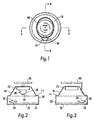
- the illustrated dispenser comprises a body portion or container 2 of moulded plastics material the circular cross-section of which increases slightly from bottom to top.
- a plurality of flexible, circumferentially spaced tabs 4 each having a normal rest position extending upwardly and inwardly of the body portion 2 as best seen in Figs 5 and 6. Conveniently there are four equi-spaced tabs 4 defining therebetween gaps 6 the width of which is greater than the maximum diameter of the tablets to be dispensed from the container 2.
- a circumferential ridge 8 is integrally moulded around the upper regions of the container 2 for reasons which will become apparent, the ridge 8 having a substantially horizontal lower surface.
- the container 2 further includes four circumferentially spaced projections 10 integrally moulded therewith around the upper regions thereof above the ridge 8, one immediately below each tab 4.
- Each projection 10 is of generally triangular configuration and includes a pair of downwardly angled upper surfaces and a transverse lower surface having a central indent 12 therein for reasons which will become apparent.
- the dispenser is completed by a moulded lid portion indicated generally at 16 and including a generally truncated conical top wall 18 from which depends a cylindrical side wall 20.
- a circular boss 22 extends downwardly from the central underside of the top wall 18, while the side wall 20 terminates in a reduced thickness extent 24 having an inwardly projecting flange 26 around the free end thereof.
- Each projection 28 includes a pair of upwardly angled lower surfaces and a transverse upper surface having a central peak 30 thereon, again for reasons which will become apparent.
- the lid portion 16 includes, between the top wall 18 and the side wall 20 a stepped rim 32.
- An aperture 34 is formed in the top wall 18 of the lid portion 16 of such a size that a single tablet of the tablet content of the container 2 can pass therethrough.
- the aperture 34 contains a disc 36 of material connected to the lid portion 16 by a circumferential strip 38 of thinner material defining a line of weakness between the lid portion 16 and the disc 36.
- a ring-pull 40 Integrally moulded with, to project upwardly from, the disc 36 is a ring-pull 40, pulling on the ring-pull 40 serving to break the strip 38 of thinner material, whereby the disc 36 is released from the lid.
- the container 2 Prior to assembly of the dispenser, the container 2 is filled with the relevant tablets, the flexible nature of the tabs 4 enabling ready access to the interior of the container 2.
- the lid portion 16 is then located above the container 2 and is pushed down onto the container 2. In so doing the tabs 4 are received within the side wall 20 and engage the underside of the top wall 18.
- the aperture 34 in the lid portion 16 overlies one of the tabs 4 so that the dispenser is initially closed.
- the projections 10, 28 which are so positioned that, if the aperture is not circumferentially aligned with a tab 4, the tapering surfaces of the projections on the lid portion 16 and the container 2 abut one another, continued downward movement of the lid portion 16 relative to the container 2 resulting in rotation of the lid portion 16 on the container 2 such that, on complete assembly, the aperture overlies a tab 4, the projections 10, 28 then being circumferentially aligned to prevent further rotation of the lid portion 16 on the container 2.
- Opening of the dispenser is achieved by first of all depressing the lid portion 16 downwardly against the bias of the spring legs 14 to move the projections 28 on the lid portion 16 below the level of the projections 10 on the container 2.
- This downward movement of the lid portion 16 is accommodated by the container 2, in that there is space within the extent 24 of the side wall 20 of the lid portion 16 to retain therein the ridge 8, while there is space above the tabs 4 to allow the downward movement of the lid portion 16.
- the lid portion 16 can be rotated to move the aperture 34 into alignment with a gap 6 between two adjacent tabs 4 whereby one tablet at a time can be poured or shaken from the container 2 on inversion of the dispenser.
- the projections 10,28 are longitudinally aligned, with the projections 28 each below an associated projection 10.
- the spring legs 14 constantly bias the lid portion 16 upwards relative to the container 2 whereby the peaks 30 on the projections 28 are urged into engagement with the indents 12 in the associated projections 10, thereby positively to determine said open position of the dispenser.
- a lightweight dispenser of relatively simple construction that is relatively cheap to manufacture and assemble and which incorporates an in-built child resistant feature which also serves to facilitate operation without the necessity for finger gripping.
- the precise construction of the dispenser can vary from that described and illustrated.
- the number and locations of the tabs 4 and gaps 6 can be altered to suit particular requirements, as can the number and locations of the projections 10, 28 providing there are as many projections on one of the lid portion 16 or container 2 as there are tabs 4, and there is at least one projection on the other of the lid portion 16 or container 2. It is however preferred that there are equal numbers of projections 10, 28 and tabs 4.
- the resilient means may be other than spring legs 14, for example a circumferentially undulating spring member, while the dispenser may or may not incorporate the tamper evident feature detailed above.
Landscapes
- Engineering & Computer Science (AREA)
- Mechanical Engineering (AREA)
- Closures For Containers (AREA)
- Encapsulation Of And Coatings For Semiconductor Or Solid State Devices (AREA)
- Formation And Processing Of Food Products (AREA)
- Medicinal Preparation (AREA)
Abstract
Description
Claims (6)
- A tablet dispenser comprising a moulded, upwardly-open body portion (2) of generally circular cross-section, a plurality of flexible, circumferentially spaced tabs (4) integrally moulded with the body portion (2) around the upper end thereof to extend upwardly therefrom whereby gaps (6) are defined between adjacent tabs (4), a lid portion (16) located on the upper end of the body portion (2) to encase the tabs (4) whereby the tabs (4) underlie the inner surface of the lid portion (16), the lid portion (16) having an aperture (34) formed therethrough, and co-operating location means (10, 28) on the body portion (2) and the lid portion (16) so positioned that, on initial assembly of the dispenser, the lid portion (16) is located on the body portion (2) with the aperture (34) in the lid portion (16) overlying a tab (4) to define a closed position of the dispenser, the lid portion (16) being rotatable relative to the body portion (2) from said closed position to an open position in which the aperture (34) in the lid portion (16) is aligned with a gap (6) between two adjacent tabs (4), characterised in that resilient means (14) react between the body portion (2) and the lid portion (16) such that, to enable relative rotation of the lid portion (16) on the body portion (2) from the closed position to the open position, it is first of all necessary to depress the lid portion (16) against the bias of the resilient means (14) to release the lid portion (16) into a position whereby it can be rotated to the open position, and,further characterised in that the co-operating location means comprise, on one of the outer surface of the upper regions of the body portion (2) and the inner surface of the lower regions of the lid portion (16), a plurality of circumferentially spaced first projections (10), one for each tab (4), each projection (10) having a surface thereto extending at an acute angle to the longitudinal central axis of the body portion (2), and, on the other of the outer surface of the upper regions of the body portion (2) and the inner surface of the lower regions of the lid portion (16), at least one second projection (28) having a surface thereto at an angle corresponding to that of the surface on the first projections (10) whereby, on initial assembly of the dispenser, the angled surfaces of the first and second projections (10, 28) abut one another and guide the lid portion (16) to a closed position on the body portion (2), the first and second projections (10, 28), in the closed position of the dispenser, being circumferentially aligned and abutting one another to prevent relative rotation between the lid portion (16) and the body portion (2).
- A tablet dispenser as claimed in claim 1 in which the resilient means comprise a plurality of circumferentially spaced spring legs (14) integrally moulded with the upper regions of the body portion (2), the arrangement being such that, with the dispenser in its closed position, the spring legs (14) react against a rim internally of the lid portion (16) to align circumferentially the first and second projections (10, 28) to prevent relative rotation therebetween, depression of the lid portion (16) against the bias of the spring legs (14) displacing the projection or projections (28) thereon below those on the body portion (2) to permit relative rotation between the lid portion (16) and the body portion (2).
- A tablet dispenser as claimed in claim 1 or claim 2 in which, in the open position of the dispenser, the projections (10, 28) on the lid portion (16) and the body portion (2) are longitudinally aligned, the resilient means (14), on release of the lid portion (16), urging aligned projections (10, 28) into engagement with one another.
- A tablet dispenser as claimed in claim 3 in which the abutting surfaces of the projections (10, 28) are configured to interlock with one another positively to define said open position of the dispenser.
- A tablet dispenser as claimed in any one of claims 1 to 4 in which the aperture (34) in the lid portion (16) is closed by a disc (36) integrally moulded with the lid portion (16) and attached thereto by a region of weakness (38), which can be broken to release the disc (36) from the aperture (34) and to open the aperture (34) for dispensing purposes.
- A tablet dispenser as claimed in claim 5 in which the region of weakness comprises a circumferential strip (38) of material thinner than that of the lid portion (16).
Applications Claiming Priority (3)
| Application Number | Priority Date | Filing Date | Title |
|---|---|---|---|
| GB9910145 | 1999-04-30 | ||
| GBGB9910145.3A GB9910145D0 (en) | 1999-04-30 | 1999-04-30 | Tablet dispenser |
| PCT/GB2000/001608 WO2000066457A1 (en) | 1999-04-30 | 2000-04-26 | Tablet dispenser |
Publications (2)
| Publication Number | Publication Date |
|---|---|
| EP1175354A1 EP1175354A1 (en) | 2002-01-30 |
| EP1175354B1 true EP1175354B1 (en) | 2003-09-24 |
Family
ID=10852668
Family Applications (1)
| Application Number | Title | Priority Date | Filing Date |
|---|---|---|---|
| EP00925487A Expired - Lifetime EP1175354B1 (en) | 1999-04-30 | 2000-04-26 | Tablet dispenser |
Country Status (7)
| Country | Link |
|---|---|
| US (1) | US6527140B1 (en) |
| EP (1) | EP1175354B1 (en) |
| AT (1) | ATE250539T1 (en) |
| AU (1) | AU4421000A (en) |
| DE (1) | DE60005498T2 (en) |
| GB (1) | GB9910145D0 (en) |
| WO (1) | WO2000066457A1 (en) |
Families Citing this family (1)
| Publication number | Priority date | Publication date | Assignee | Title |
|---|---|---|---|---|
| CA2541021C (en) * | 2003-10-02 | 2010-12-07 | Capitol Plastic Products, Llc | Container with pill dispensing insert |
Family Cites Families (4)
| Publication number | Priority date | Publication date | Assignee | Title |
|---|---|---|---|---|
| NL6918357A (en) * | 1969-12-05 | 1971-06-08 | ||
| US3762539A (en) * | 1971-07-22 | 1973-10-02 | G Kerr | Pill dispenser |
| US4376497A (en) * | 1980-09-15 | 1983-03-15 | Owens-Illinois, Inc. | Child resistant dispensing closure |
| GB9116864D0 (en) * | 1991-08-05 | 1991-09-18 | Audus Noble Ltd | Tablet dispenser |
-
1999
- 1999-04-30 GB GBGB9910145.3A patent/GB9910145D0/en not_active Ceased
-
2000
- 2000-04-26 DE DE60005498T patent/DE60005498T2/en not_active Expired - Fee Related
- 2000-04-26 EP EP00925487A patent/EP1175354B1/en not_active Expired - Lifetime
- 2000-04-26 WO PCT/GB2000/001608 patent/WO2000066457A1/en not_active Ceased
- 2000-04-26 AT AT00925487T patent/ATE250539T1/en not_active IP Right Cessation
- 2000-04-26 AU AU44210/00A patent/AU4421000A/en not_active Abandoned
- 2000-04-26 US US09/959,524 patent/US6527140B1/en not_active Expired - Fee Related
Also Published As
| Publication number | Publication date |
|---|---|
| DE60005498T2 (en) | 2004-07-22 |
| WO2000066457A1 (en) | 2000-11-09 |
| EP1175354A1 (en) | 2002-01-30 |
| GB9910145D0 (en) | 1999-06-30 |
| US6527140B1 (en) | 2003-03-04 |
| ATE250539T1 (en) | 2003-10-15 |
| AU4421000A (en) | 2000-11-17 |
| DE60005498D1 (en) | 2003-10-30 |
Similar Documents
| Publication | Publication Date | Title |
|---|---|---|
| US4171057A (en) | Child-resistant medicine vial | |
| US5865330A (en) | Child resistant cap | |
| AU720185B2 (en) | Child-resistant container and closure assembly | |
| US5228593A (en) | Container-closure assembly | |
| US4832218A (en) | Child-resistant closure device | |
| US4787526A (en) | Container closure having child protective fastening means | |
| US4071156A (en) | Child resistant container-closure assembly | |
| US4925041A (en) | Closure for container | |
| US6338408B1 (en) | Device for holding blister pack | |
| US6202869B1 (en) | Child-resistant/senior-friendly container | |
| GB2207909A (en) | Tamper-evident closure for dispensers | |
| US6095364A (en) | Child-resistant closure for pill containers | |
| MXPA02010416A (en) | Dispensing closure with tamper evident lid panel. | |
| US4565294A (en) | Tamper evident container shroud | |
| US5722568A (en) | Tamper-evident aerosol cap | |
| JPS6111358A (en) | Safety cover for vessel | |
| US5921417A (en) | Large diameter safety closure | |
| US4315576A (en) | Child resistant closure cap apparatus employing fulcrum action | |
| US5246123A (en) | Conversion apparatus for child-resistant container closure | |
| US4775062A (en) | Child resistant closure cap for necked cans or containers | |
| EP0401292B1 (en) | Hinged closure for containers | |
| US5509580A (en) | Child resistant cap for sprayers | |
| US6527140B1 (en) | Tablet dispenser | |
| US6112920A (en) | Child-proof, senior-friendly pill bottle closure | |
| US4662542A (en) | Safety closure for aerosol cans |
Legal Events
| Date | Code | Title | Description |
|---|---|---|---|
| PUAI | Public reference made under article 153(3) epc to a published international application that has entered the european phase |
Free format text: ORIGINAL CODE: 0009012 |
|
| 17P | Request for examination filed |
Effective date: 20011025 |
|
| AK | Designated contracting states |
Kind code of ref document: A1 Designated state(s): AT BE CH CY DE DK ES FI FR GB GR IE IT LI LU MC NL PT SE |
|
| GRAH | Despatch of communication of intention to grant a patent |
Free format text: ORIGINAL CODE: EPIDOS IGRA |
|
| GRAH | Despatch of communication of intention to grant a patent |
Free format text: ORIGINAL CODE: EPIDOS IGRA |
|
| GRAA | (expected) grant |
Free format text: ORIGINAL CODE: 0009210 |
|
| AK | Designated contracting states |
Kind code of ref document: B1 Designated state(s): AT BE CH CY DE DK ES FI FR GB GR IE IT LI LU MC NL PT SE |
|
| PG25 | Lapsed in a contracting state [announced via postgrant information from national office to epo] |
Ref country code: NL Free format text: LAPSE BECAUSE OF FAILURE TO SUBMIT A TRANSLATION OF THE DESCRIPTION OR TO PAY THE FEE WITHIN THE PRESCRIBED TIME-LIMIT Effective date: 20030924 Ref country code: LI Free format text: LAPSE BECAUSE OF FAILURE TO SUBMIT A TRANSLATION OF THE DESCRIPTION OR TO PAY THE FEE WITHIN THE PRESCRIBED TIME-LIMIT Effective date: 20030924 Ref country code: IT Free format text: LAPSE BECAUSE OF FAILURE TO SUBMIT A TRANSLATION OF THE DESCRIPTION OR TO PAY THE FEE WITHIN THE PRESCRIBED TIME-LIMIT;WARNING: LAPSES OF ITALIAN PATENTS WITH EFFECTIVE DATE BEFORE 2007 MAY HAVE OCCURRED AT ANY TIME BEFORE 2007. THE CORRECT EFFECTIVE DATE MAY BE DIFFERENT FROM THE ONE RECORDED. Effective date: 20030924 Ref country code: FI Free format text: LAPSE BECAUSE OF FAILURE TO SUBMIT A TRANSLATION OF THE DESCRIPTION OR TO PAY THE FEE WITHIN THE PRESCRIBED TIME-LIMIT Effective date: 20030924 Ref country code: CY Free format text: LAPSE BECAUSE OF FAILURE TO SUBMIT A TRANSLATION OF THE DESCRIPTION OR TO PAY THE FEE WITHIN THE PRESCRIBED TIME-LIMIT Effective date: 20030924 Ref country code: CH Free format text: LAPSE BECAUSE OF FAILURE TO SUBMIT A TRANSLATION OF THE DESCRIPTION OR TO PAY THE FEE WITHIN THE PRESCRIBED TIME-LIMIT Effective date: 20030924 Ref country code: BE Free format text: LAPSE BECAUSE OF FAILURE TO SUBMIT A TRANSLATION OF THE DESCRIPTION OR TO PAY THE FEE WITHIN THE PRESCRIBED TIME-LIMIT Effective date: 20030924 Ref country code: AT Free format text: LAPSE BECAUSE OF FAILURE TO SUBMIT A TRANSLATION OF THE DESCRIPTION OR TO PAY THE FEE WITHIN THE PRESCRIBED TIME-LIMIT Effective date: 20030924 |
|
| REG | Reference to a national code |
Ref country code: GB Ref legal event code: FG4D |
|
| REG | Reference to a national code |
Ref country code: CH Ref legal event code: EP |
|
| REG | Reference to a national code |
Ref country code: IE Ref legal event code: FG4D |
|
| REF | Corresponds to: |
Ref document number: 60005498 Country of ref document: DE Date of ref document: 20031030 Kind code of ref document: P |
|
| PG25 | Lapsed in a contracting state [announced via postgrant information from national office to epo] |
Ref country code: SE Free format text: LAPSE BECAUSE OF FAILURE TO SUBMIT A TRANSLATION OF THE DESCRIPTION OR TO PAY THE FEE WITHIN THE PRESCRIBED TIME-LIMIT Effective date: 20031224 Ref country code: GR Free format text: LAPSE BECAUSE OF FAILURE TO SUBMIT A TRANSLATION OF THE DESCRIPTION OR TO PAY THE FEE WITHIN THE PRESCRIBED TIME-LIMIT Effective date: 20031224 Ref country code: DK Free format text: LAPSE BECAUSE OF FAILURE TO SUBMIT A TRANSLATION OF THE DESCRIPTION OR TO PAY THE FEE WITHIN THE PRESCRIBED TIME-LIMIT Effective date: 20031224 |
|
| PG25 | Lapsed in a contracting state [announced via postgrant information from national office to epo] |
Ref country code: ES Free format text: LAPSE BECAUSE OF FAILURE TO SUBMIT A TRANSLATION OF THE DESCRIPTION OR TO PAY THE FEE WITHIN THE PRESCRIBED TIME-LIMIT Effective date: 20040104 |
|
| NLV1 | Nl: lapsed or annulled due to failure to fulfill the requirements of art. 29p and 29m of the patents act | ||
| REG | Reference to a national code |
Ref country code: CH Ref legal event code: PL |
|
| PG25 | Lapsed in a contracting state [announced via postgrant information from national office to epo] |
Ref country code: LU Free format text: LAPSE BECAUSE OF NON-PAYMENT OF DUE FEES Effective date: 20040426 Ref country code: IE Free format text: LAPSE BECAUSE OF NON-PAYMENT OF DUE FEES Effective date: 20040426 |
|
| PG25 | Lapsed in a contracting state [announced via postgrant information from national office to epo] |
Ref country code: MC Free format text: LAPSE BECAUSE OF NON-PAYMENT OF DUE FEES Effective date: 20040430 |
|
| ET | Fr: translation filed | ||
| PLBE | No opposition filed within time limit |
Free format text: ORIGINAL CODE: 0009261 |
|
| STAA | Information on the status of an ep patent application or granted ep patent |
Free format text: STATUS: NO OPPOSITION FILED WITHIN TIME LIMIT |
|
| 26N | No opposition filed |
Effective date: 20040625 |
|
| REG | Reference to a national code |
Ref country code: IE Ref legal event code: MM4A |
|
| PGFP | Annual fee paid to national office [announced via postgrant information from national office to epo] |
Ref country code: GB Payment date: 20060420 Year of fee payment: 7 |
|
| PGFP | Annual fee paid to national office [announced via postgrant information from national office to epo] |
Ref country code: FR Payment date: 20060424 Year of fee payment: 7 |
|
| PGFP | Annual fee paid to national office [announced via postgrant information from national office to epo] |
Ref country code: DE Payment date: 20060427 Year of fee payment: 7 |
|
| GBPC | Gb: european patent ceased through non-payment of renewal fee |
Effective date: 20070426 |
|
| PG25 | Lapsed in a contracting state [announced via postgrant information from national office to epo] |
Ref country code: PT Free format text: LAPSE BECAUSE OF NON-PAYMENT OF DUE FEES Effective date: 20040224 |
|
| PG25 | Lapsed in a contracting state [announced via postgrant information from national office to epo] |
Ref country code: DE Free format text: LAPSE BECAUSE OF NON-PAYMENT OF DUE FEES Effective date: 20071101 |
|
| PG25 | Lapsed in a contracting state [announced via postgrant information from national office to epo] |
Ref country code: GB Free format text: LAPSE BECAUSE OF NON-PAYMENT OF DUE FEES Effective date: 20070426 |
|
| PG25 | Lapsed in a contracting state [announced via postgrant information from national office to epo] |
Ref country code: FR Free format text: LAPSE BECAUSE OF NON-PAYMENT OF DUE FEES Effective date: 20070430 |