EP1175243B1 - Cardiac defibrillation - Google Patents
Cardiac defibrillation Download PDFInfo
- Publication number
- EP1175243B1 EP1175243B1 EP00927514A EP00927514A EP1175243B1 EP 1175243 B1 EP1175243 B1 EP 1175243B1 EP 00927514 A EP00927514 A EP 00927514A EP 00927514 A EP00927514 A EP 00927514A EP 1175243 B1 EP1175243 B1 EP 1175243B1
- Authority
- EP
- European Patent Office
- Prior art keywords
- circuit
- implantable
- external circuit
- ecg
- resonance
- Prior art date
- Legal status (The legal status is an assumption and is not a legal conclusion. Google has not performed a legal analysis and makes no representation as to the accuracy of the status listed.)
- Expired - Lifetime
Links
- 230000000747 cardiac effect Effects 0.000 title claims description 7
- 230000006698 induction Effects 0.000 claims abstract description 7
- 230000008878 coupling Effects 0.000 claims description 6
- 238000010168 coupling process Methods 0.000 claims description 6
- 238000005859 coupling reaction Methods 0.000 claims description 6
- 230000001939 inductive effect Effects 0.000 claims description 6
- 238000007493 shaping process Methods 0.000 claims description 6
- 230000001746 atrial effect Effects 0.000 abstract description 7
- 206010003658 Atrial Fibrillation Diseases 0.000 description 5
- 238000000034 method Methods 0.000 description 4
- 230000005540 biological transmission Effects 0.000 description 3
- 230000002051 biphasic effect Effects 0.000 description 3
- RYGMFSIKBFXOCR-UHFFFAOYSA-N Copper Chemical compound [Cu] RYGMFSIKBFXOCR-UHFFFAOYSA-N 0.000 description 2
- 206010039897 Sedation Diseases 0.000 description 2
- 206010003119 arrhythmia Diseases 0.000 description 2
- 239000003990 capacitor Substances 0.000 description 2
- 238000013194 cardioversion Methods 0.000 description 2
- 238000004891 communication Methods 0.000 description 2
- 230000001862 defibrillatory effect Effects 0.000 description 2
- 239000007943 implant Substances 0.000 description 2
- 238000012544 monitoring process Methods 0.000 description 2
- 210000000056 organ Anatomy 0.000 description 2
- 210000005245 right atrium Anatomy 0.000 description 2
- 230000036280 sedation Effects 0.000 description 2
- 230000035939 shock Effects 0.000 description 2
- 230000000638 stimulation Effects 0.000 description 2
- 206010002091 Anaesthesia Diseases 0.000 description 1
- 238000001949 anaesthesia Methods 0.000 description 1
- 230000037005 anaesthesia Effects 0.000 description 1
- 230000006793 arrhythmia Effects 0.000 description 1
- 238000006243 chemical reaction Methods 0.000 description 1
- 210000003748 coronary sinus Anatomy 0.000 description 1
- 230000000694 effects Effects 0.000 description 1
- 238000007689 inspection Methods 0.000 description 1
- 238000003909 pattern recognition Methods 0.000 description 1
- 230000000144 pharmacologic effect Effects 0.000 description 1
- 238000007670 refining Methods 0.000 description 1
- 230000033764 rhythmic process Effects 0.000 description 1
- 230000001360 synchronised effect Effects 0.000 description 1
- 210000000779 thoracic wall Anatomy 0.000 description 1
- 210000003462 vein Anatomy 0.000 description 1
- 230000002861 ventricular Effects 0.000 description 1
Images

Classifications
-
- A—HUMAN NECESSITIES
- A61—MEDICAL OR VETERINARY SCIENCE; HYGIENE
- A61N—ELECTROTHERAPY; MAGNETOTHERAPY; RADIATION THERAPY; ULTRASOUND THERAPY
- A61N1/00—Electrotherapy; Circuits therefor
- A61N1/18—Applying electric currents by contact electrodes
- A61N1/32—Applying electric currents by contact electrodes alternating or intermittent currents
- A61N1/38—Applying electric currents by contact electrodes alternating or intermittent currents for producing shock effects
- A61N1/39—Heart defibrillators
- A61N1/3956—Implantable devices for applying electric shocks to the heart, e.g. for cardioversion
-
- A—HUMAN NECESSITIES
- A61—MEDICAL OR VETERINARY SCIENCE; HYGIENE
- A61N—ELECTROTHERAPY; MAGNETOTHERAPY; RADIATION THERAPY; ULTRASOUND THERAPY
- A61N1/00—Electrotherapy; Circuits therefor
- A61N1/18—Applying electric currents by contact electrodes
- A61N1/32—Applying electric currents by contact electrodes alternating or intermittent currents
- A61N1/36—Applying electric currents by contact electrodes alternating or intermittent currents for stimulation
- A61N1/372—Arrangements in connection with the implantation of stimulators
- A61N1/378—Electrical supply
- A61N1/3787—Electrical supply from an external energy source
Definitions
- This invention relates to cardiac defibrillation, and in particular (but not exclusively) to an apparatus for delivering an electrical defibrillating signal to a human heart in the state of atrial fibrillation (AF), using transdermal energy transfer to a passive implanted device.
- AF atrial fibrillation
- Atrial fibrillation is a common heart arrhythmia that increases in prevalence with age, with typically 10% of people over the age of 70 experiencing an incident.
- SR normal sinus rhythm
- the process of cardioversion of AF to normal sinus rhythm (SR) has traditionally been attempted by pharmacological measures or transthoracic direct current shock.
- the former has been limited by variable cardioversion rates and the risk of side effects, in particular proarrhythmia.
- the latter requires sedation or anaesthesia and high energy shocks, and there is a high recurrence rate.
- catheter-based transvenous atrial defibrillation and its potential use in an implantable atrial defibrillator.
- atrial implantable defibrillators are complex devices requiring on-board pattern recognition with complex recording and follow-up procedures.
- the need for electrical charging circuitry using active devices adds to the complexity and weight of the implant.
- US 3,796,221 discloses an implantable apparatus for delivering low energy electrical stimulation to a body organ transdermally.
- the apparatus receives a signal from an external device as to when to provide an electrical signal to the body organ independently of the strength of the received signal.
- US 5,411,537 discloses a rechargeable battery powered bio-medical device such as cardioverter-defibrillator.
- the battery may be charged transdermally and the device may also provide high-energy pulses from the rechargeable battery.
- the present invention provides an apparatus for cardiac defibrillation which comprises an external circuit and an implantable circuit; the external circuit including an induction transmitting coil and signal generating means for applying radio frequency pulses of predetermined shape to the transmitting coil; the implantable circuit including an induction receiving coil for receiving said pulses when the two coils are in proximity, and a rectification circuit having an input connected to the receiving coil and an output driving electrodes which are implantable in the heart; and in which the rectification circuit drives the electrodes directly with pulses of a shape which is determined by the signal generating means of the external circuit, wherein the power transmitted per pulse is less than about 5J and the radio frequency is in the range 3-30 MHz, preferably about 7MHz.
- the signal generating means comprises a radio frequency generator switched or gated under the control of a pulse generation showing means which in turn is responsive to an ecg synchronisation signal.
- the ecg synchronisation signal is provided via a telemetry transmitter implanted in the patient.
- the external circuit further includes a telephone link by which the ecg may be transmitted to, and/or the apparatus controlled from, a remote location.
- the external and implantable circuits include impedance matching components to achieve a high degree of tuning.
- the inductive coupling is tuned to resonance and more preferably the inductive coupling is tuned to resonance by use of series resonance in the external circuit and parallel resonance in the implantable circuit.
- the implantable circuit contains only passive components.
- the telemetry transmitter is powered from energy delivered transdermally either by using a low-power transfer to power up the telemetry transmitter or to charge an onboard battery.
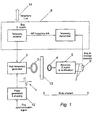
- an appropriately synchronised trigger pulse is firstly generated, based on the subject's electrocardiogram (ecg).
- This pulse after shaping in a pulse generation and shaping circuit 12 to a waveform 1 suitable for AF conversion, is used to amplitude modulate a radio frequency (RF) carrier generator 2 at a power level consistent with the transmission of 1-5 J of energy to the internal load, itself nominally 50 ⁇ resistive.
- the transmission path takes the form of a pair of coaxially-aligned transmit 3 and receive 4 inductors constructed in the form of an RF transformer.
- the diameters of the coils 3 and 4 are set so as to optimise energy transfer at a physical spacing not less than the thickness of the thoracic wall 13. Both inductors are wound with enamelled copper wire.
- the transmitting coil 3 is mounted on an insulated paddle to facilitate adjustment in its placement on the subject's body.
- the implanted circuitry is mounted on a printed circuit board and consists of the receiving coil 4 connected to impedance matching, rectification and wave-shaping components 5.
- the final defibrillating signal is connected to the heart (indicated as an electrical load 6) by catheters 7, one placed in the lateral right atrium (RA) and the other in the distal great cardiac vein via the coronary sinus.
- RA right atrium
- any conventional atrial defibrillation delivery system may be used.
- the coils 3 and 4 are designed to give optimum inductive coupling at a centre-to-centre spacing of 20mm. Given a maximum diameter, for practicability, of the receiving coil 4 of 35mm, the transmitting coil 3 has a diameter of 53mm. Both inductors are wound with 1.5mm enamelled copper wire. The transmitting coil 3 is arranged as a solenoidal coil, spaced at one turn. The receiving coil 4 is pile-wound to conserve space in the final implant.
- Both inductors in the apparatus are tuned to resonance at the selected operating frequency of the system, typically in the range 3-30 MHz.
- the transmitter uses series tuning by capacitor 9.
- Fig. 2 also shows a 50 ohm feed 15 from the generator 2, giving an operational loaded Q of approximately 5.
- the receiving coil is parallel tuned, with capacitive matching to the load 6 by means of capacitors C1 and C2.
- a radio-frequency choke 11 provides a DC path for rectifier current.
- Rectification and shaping is effected in circuit 16.
- a telemetry link 8 may be incorporated to provide ecg monitoring and feedback-derived, automatic tuning of the energy delivery system.
- Such a link may also be powered from energy delivered transdermally, by using a low-power transfer to power up the telemetry link, or to charge an on-board battery.
- the ecg could be transmitted via the induction coils using a suspended carrier technique.
- the external circuitry may include a remote communication link 14, which may be via telephone communication (landline or GSM) or via a radio link.
- a remote communication link 14 may be via telephone communication (landline or GSM) or via a radio link. This would, for example, enable the patient's ecg to be transmitted to a hospital for monitoring and for inspection by a physician. Defibrillation could be activated remotely, and spoken instructions could be conveyed to the patient.
- Atrial defibrillation currently requires a pulse energy of about 3 to 4J.
- a tuned inductive coupling typically at a frequency about 7 MHz, these energy levels can be transmitted transdermally while maintaining control of pulse shape and timing.
- the pulse form 1 shown in Figure 1 is a biphasic pulse, which is the form we currently prefer. However, other pulse forms and hence RF envelope shapes may also be used, such as monophasic and multiple.
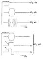
- Fig. 4 illustrates waveforms of the apparatus in more detail.
- Fig. 4a is a typical trigger input from an ecg.
- Fig. 4b shows a typical RF output envelope to the coil 3 as a single pulse.
- Fig. 4c shows an alternative RF output envelope as a burst of two or more pulses. All pulses can be controlled in width, and the inter-pulse gap of Fig. 4c is programmable.
- Each RF pulse after transmission and rectification, results in either a monophasic or a biphasic (baseband) voltage waveform suitable for driving the cardiac load.
- Fig. 4d shows a monophasic pulse 17 and a biphasic pulse 18 which can be produced from the single pulse of Fig. 4a.
- the invention could find use in ventricular defibrillation.
- the required energy levels are much higher (typically about 15J).
- the implanted hardware is entirely passive and does not require any implanted power source.
- the invention does not exclude the possibility of some active components being implanted, with a reduced requirement for an internal source of power.
Landscapes
- Health & Medical Sciences (AREA)
- Animal Behavior & Ethology (AREA)
- Public Health (AREA)
- Engineering & Computer Science (AREA)
- Biomedical Technology (AREA)
- Nuclear Medicine, Radiotherapy & Molecular Imaging (AREA)
- Radiology & Medical Imaging (AREA)
- Veterinary Medicine (AREA)
- Life Sciences & Earth Sciences (AREA)
- General Health & Medical Sciences (AREA)
- Cardiology (AREA)
- Heart & Thoracic Surgery (AREA)
- Electrotherapy Devices (AREA)
- Materials For Photolithography (AREA)
- Measuring Volume Flow (AREA)
- Amplifiers (AREA)
- Fish Paste Products (AREA)
Abstract
Description
Claims (9)
- An apparatus for cardiac defibrillation which comprises:characterised in that the power transmitted per pulse is less than about 5J and the radio frequency is in the range 3-30 MHz, preferably about 7MHz.an external circuit and an implantable circuit;the external circuit including an induction transmitting coil (3) and signal generating means (12) for applying radio frequency pulses of predetermined shape to the transmitting coil (3);the implantable circuit including an induction receiving coil (4) for receiving said pulses when the two coils are in proximity, and a rectification and shaping circuit (5) having an input connected to the receiving coil (4) and an output driving electrodes (7) which are implantable in the heart (6); andin which the rectification and shaping circuit (4) drives the electrodes (7) directly with pulses of a shape which is determined by the signal generating means (12) of the external circuit,
- An apparatus according to Claim 1, in which the signal generating means (12) comprises a radio frequency generator switched or gated under the control of a pulse generation showing means which in turn is responsive to an ecg synchronisation signal.
- An apparatus according to Claim 2, in which ecg synchronisation signal is provided via a telemetry transmitter (8) implanted in the patient.
- An apparatus according to any preceding Claim, in which external circuit further includes a telephone link (14) by which the ecg may be transmitted to, and/or the apparatus controlled from, a remote location.
- An apparatus according to any preceding Claim, in which external and implantable circuits include impedance matching components to achieve a high degree of tuning.
- An apparatus according to Claim 5, in which the inductive coupling is tuned to resonance.
- An apparatus according to Claim 7, in which the inductive coupling is tuned to resonance by use of series resonance in the external circuit and parallel resonance in the implantable circuit.
- An apparatus according to any preceding Claim, in which the implantable circuit contains only passive components.
- An apparatus according to Claim 3, in which the telemetry transmitter is powered from energy delivered transdermally either by using a low-power transfer to power up the telemetry transmitter or to charge an onboard battery.
Applications Claiming Priority (3)
| Application Number | Priority Date | Filing Date | Title |
|---|---|---|---|
| GBGB9910323.6A GB9910323D0 (en) | 1999-05-06 | 1999-05-06 | Cardiac defibrillation |
| GB9910323 | 1999-05-06 | ||
| PCT/GB2000/001725 WO2000067843A1 (en) | 1999-05-06 | 2000-05-05 | Cardiac defibrillation |
Publications (2)
| Publication Number | Publication Date |
|---|---|
| EP1175243A1 EP1175243A1 (en) | 2002-01-30 |
| EP1175243B1 true EP1175243B1 (en) | 2004-08-11 |
Family
ID=10852799
Family Applications (1)
| Application Number | Title | Priority Date | Filing Date |
|---|---|---|---|
| EP00927514A Expired - Lifetime EP1175243B1 (en) | 1999-05-06 | 2000-05-05 | Cardiac defibrillation |
Country Status (9)
| Country | Link |
|---|---|
| US (1) | US7110812B1 (en) |
| EP (1) | EP1175243B1 (en) |
| JP (1) | JP4189548B2 (en) |
| AT (1) | ATE273045T1 (en) |
| AU (1) | AU4591100A (en) |
| DE (1) | DE60012909T2 (en) |
| ES (1) | ES2225133T3 (en) |
| GB (1) | GB9910323D0 (en) |
| WO (1) | WO2000067843A1 (en) |
Families Citing this family (6)
| Publication number | Priority date | Publication date | Assignee | Title |
|---|---|---|---|---|
| EP2587275B8 (en) * | 2006-12-22 | 2015-07-15 | Koninklijke Philips N.V. | Catheter for MRI-guided cardiac pacing |
| DE202007018530U1 (en) * | 2007-05-11 | 2008-11-20 | Chamalow S.A. | Radio frequency coil for "R" wave synchronous stimulation |
| DE202007018531U1 (en) * | 2007-05-11 | 2008-10-30 | Chamalow S.A. | Dual chamber pacing coils for atrial defibrillation and ventricular pacing |
| DE202007018529U1 (en) * | 2007-07-07 | 2008-12-04 | Chamalow S.A. | Implantable Radio Frequency Defibrillator R.F. |
| GB201106982D0 (en) * | 2011-04-27 | 2011-06-08 | Univ Ulster | Defobrillator apparatus and method |
| CA2879955C (en) * | 2012-07-26 | 2021-08-10 | Adi Mashiach | Implant sleep apnea treatment device including an antenna |
Family Cites Families (8)
| Publication number | Priority date | Publication date | Assignee | Title |
|---|---|---|---|---|
| US3796221A (en) * | 1971-07-07 | 1974-03-12 | N Hagfors | Apparatus for delivering electrical stimulation energy to body-implanted apparatus with signal-receiving means |
| US4549547A (en) | 1982-07-27 | 1985-10-29 | Trustees Of The University Of Pennsylvania | Implantable bone growth stimulator |
| US5411537A (en) | 1993-10-29 | 1995-05-02 | Intermedics, Inc. | Rechargeable biomedical battery powered devices with recharging and control system therefor |
| US5630836A (en) * | 1995-01-19 | 1997-05-20 | Vascor, Inc. | Transcutaneous energy and information transmission apparatus |
| US5697958A (en) * | 1995-06-07 | 1997-12-16 | Intermedics, Inc. | Electromagnetic noise detector for implantable medical devices |
| US5735887A (en) | 1996-12-10 | 1998-04-07 | Exonix Corporation | Closed-loop, RF-coupled implanted medical device |
| US6016449A (en) * | 1997-10-27 | 2000-01-18 | Neuropace, Inc. | System for treatment of neurological disorders |
| US6321117B1 (en) * | 1999-08-20 | 2001-11-20 | Cardiac Pacemakers, Inc. | Change log for implantable medical device |
-
1999
- 1999-05-06 GB GBGB9910323.6A patent/GB9910323D0/en not_active Ceased
-
2000
- 2000-05-05 AU AU45911/00A patent/AU4591100A/en not_active Abandoned
- 2000-05-05 ES ES00927514T patent/ES2225133T3/en not_active Expired - Lifetime
- 2000-05-05 DE DE60012909T patent/DE60012909T2/en not_active Expired - Lifetime
- 2000-05-05 JP JP2000616864A patent/JP4189548B2/en not_active Expired - Fee Related
- 2000-05-05 WO PCT/GB2000/001725 patent/WO2000067843A1/en not_active Ceased
- 2000-05-05 US US09/980,971 patent/US7110812B1/en not_active Expired - Fee Related
- 2000-05-05 EP EP00927514A patent/EP1175243B1/en not_active Expired - Lifetime
- 2000-05-05 AT AT00927514T patent/ATE273045T1/en not_active IP Right Cessation
Also Published As
| Publication number | Publication date |
|---|---|
| AU4591100A (en) | 2000-11-21 |
| WO2000067843A1 (en) | 2000-11-16 |
| ATE273045T1 (en) | 2004-08-15 |
| ES2225133T3 (en) | 2005-03-16 |
| US7110812B1 (en) | 2006-09-19 |
| JP4189548B2 (en) | 2008-12-03 |
| JP2002543895A (en) | 2002-12-24 |
| DE60012909T2 (en) | 2005-08-25 |
| DE60012909D1 (en) | 2004-09-16 |
| EP1175243A1 (en) | 2002-01-30 |
| GB9910323D0 (en) | 1999-06-30 |
Similar Documents
| Publication | Publication Date | Title |
|---|---|---|
| US7657311B2 (en) | Subcutaneous only implantable cardioverter-defibrillator and optional pacer | |
| US7751881B2 (en) | Acoustically-powered wireless defibrillator | |
| US6952610B2 (en) | Current waveforms for anti-tachycardia pacing for a subcutaneous implantable cardioverter- defibrillator | |
| US8768458B2 (en) | Unitary subcutaneous only implantable cardioverter-defibrillator | |
| US7092754B2 (en) | Monophasic waveform for anti-bradycardia pacing for a subcutaneous implantable cardioverter-defibrillator | |
| US20080294210A1 (en) | Leadless Implantable Cardioverter Defibrillator | |
| US20070179540A1 (en) | Subcutaneous ICD with separate cardiac rhythm sensor | |
| US20020183791A1 (en) | Implantable defibrillator with wireless vascular stent electrodes | |
| US20050143778A1 (en) | Current waveforms for anti-bradycardia pacing for a subcutaneous implantable cardioverter-defibrillator | |
| US20180339161A1 (en) | Tachyarrhythmia induction by an extra-cardiovascular implantable cardioverter defibrillator | |
| US20130190833A1 (en) | Use of Electric Fields for Reducing Patient Discomfort During Defibrillation | |
| WO2003018128A1 (en) | Power supply for a subcutaneously implantable cardioverter-defibrillator | |
| WO2006115877A1 (en) | Vagal nerve stimulation using vascular implanted devices for treatment of atrial fibrillation | |
| US7110812B1 (en) | Cardiac defibrillation | |
| US20220305256A1 (en) | Systems, devices, and related methods for cardiac arrhythmia therapy | |
| Santos et al. | Atrial defibrillation using low tilt pulses delivered by transcutaneous RF coupling | |
| Manoharan et al. | Atrial defibrillation using transcutaneous radio-frequency pulse delivery | |
| Santos et al. | Transdermal atrial defibrillation with bipolar low-tilt pulses | |
| EP2155332A2 (en) | Rf coil for stimulation synchronous with the "r" wave |
Legal Events
| Date | Code | Title | Description |
|---|---|---|---|
| PUAI | Public reference made under article 153(3) epc to a published international application that has entered the european phase |
Free format text: ORIGINAL CODE: 0009012 |
|
| 17P | Request for examination filed |
Effective date: 20011113 |
|
| AK | Designated contracting states |
Kind code of ref document: A1 Designated state(s): AT BE CH CY DE DK ES FI FR GB GR IE IT LI LU MC NL PT SE |
|
| AX | Request for extension of the european patent |
Free format text: AL;LT;LV;MK;RO;SI |
|
| 17Q | First examination report despatched |
Effective date: 20030807 |
|
| GRAP | Despatch of communication of intention to grant a patent |
Free format text: ORIGINAL CODE: EPIDOSNIGR1 |
|
| GRAS | Grant fee paid |
Free format text: ORIGINAL CODE: EPIDOSNIGR3 |
|
| GRAA | (expected) grant |
Free format text: ORIGINAL CODE: 0009210 |
|
| AK | Designated contracting states |
Kind code of ref document: B1 Designated state(s): AT BE CH CY DE DK ES FI FR GB GR IE IT LI LU MC NL PT SE |
|
| PG25 | Lapsed in a contracting state [announced via postgrant information from national office to epo] |
Ref country code: NL Free format text: LAPSE BECAUSE OF FAILURE TO SUBMIT A TRANSLATION OF THE DESCRIPTION OR TO PAY THE FEE WITHIN THE PRESCRIBED TIME-LIMIT Effective date: 20040811 Ref country code: LI Free format text: LAPSE BECAUSE OF FAILURE TO SUBMIT A TRANSLATION OF THE DESCRIPTION OR TO PAY THE FEE WITHIN THE PRESCRIBED TIME-LIMIT Effective date: 20040811 Ref country code: AT Free format text: LAPSE BECAUSE OF FAILURE TO SUBMIT A TRANSLATION OF THE DESCRIPTION OR TO PAY THE FEE WITHIN THE PRESCRIBED TIME-LIMIT Effective date: 20040811 Ref country code: CH Free format text: LAPSE BECAUSE OF FAILURE TO SUBMIT A TRANSLATION OF THE DESCRIPTION OR TO PAY THE FEE WITHIN THE PRESCRIBED TIME-LIMIT Effective date: 20040811 Ref country code: BE Free format text: LAPSE BECAUSE OF FAILURE TO SUBMIT A TRANSLATION OF THE DESCRIPTION OR TO PAY THE FEE WITHIN THE PRESCRIBED TIME-LIMIT Effective date: 20040811 Ref country code: FI Free format text: LAPSE BECAUSE OF FAILURE TO SUBMIT A TRANSLATION OF THE DESCRIPTION OR TO PAY THE FEE WITHIN THE PRESCRIBED TIME-LIMIT Effective date: 20040811 |
|
| REG | Reference to a national code |
Ref country code: GB Ref legal event code: FG4D |
|
| REG | Reference to a national code |
Ref country code: CH Ref legal event code: EP |
|
| REG | Reference to a national code |
Ref country code: IE Ref legal event code: FG4D |
|
| REF | Corresponds to: |
Ref document number: 60012909 Country of ref document: DE Date of ref document: 20040916 Kind code of ref document: P |
|
| PG25 | Lapsed in a contracting state [announced via postgrant information from national office to epo] |
Ref country code: GR Free format text: LAPSE BECAUSE OF FAILURE TO SUBMIT A TRANSLATION OF THE DESCRIPTION OR TO PAY THE FEE WITHIN THE PRESCRIBED TIME-LIMIT Effective date: 20041111 Ref country code: SE Free format text: LAPSE BECAUSE OF FAILURE TO SUBMIT A TRANSLATION OF THE DESCRIPTION OR TO PAY THE FEE WITHIN THE PRESCRIBED TIME-LIMIT Effective date: 20041111 Ref country code: DK Free format text: LAPSE BECAUSE OF FAILURE TO SUBMIT A TRANSLATION OF THE DESCRIPTION OR TO PAY THE FEE WITHIN THE PRESCRIBED TIME-LIMIT Effective date: 20041111 |
|
| LTIE | Lt: invalidation of european patent or patent extension |
Effective date: 20040811 |
|
| NLV1 | Nl: lapsed or annulled due to failure to fulfill the requirements of art. 29p and 29m of the patents act | ||
| REG | Reference to a national code |
Ref country code: CH Ref legal event code: PL |
|
| REG | Reference to a national code |
Ref country code: ES Ref legal event code: FG2A Ref document number: 2225133 Country of ref document: ES Kind code of ref document: T3 |
|
| PG25 | Lapsed in a contracting state [announced via postgrant information from national office to epo] |
Ref country code: CY Free format text: LAPSE BECAUSE OF FAILURE TO SUBMIT A TRANSLATION OF THE DESCRIPTION OR TO PAY THE FEE WITHIN THE PRESCRIBED TIME-LIMIT Effective date: 20050505 Ref country code: LU Free format text: LAPSE BECAUSE OF NON-PAYMENT OF DUE FEES Effective date: 20050505 Ref country code: IE Free format text: LAPSE BECAUSE OF NON-PAYMENT OF DUE FEES Effective date: 20050505 |
|
| ET | Fr: translation filed | ||
| PG25 | Lapsed in a contracting state [announced via postgrant information from national office to epo] |
Ref country code: MC Free format text: LAPSE BECAUSE OF NON-PAYMENT OF DUE FEES Effective date: 20050531 |
|
| PLBE | No opposition filed within time limit |
Free format text: ORIGINAL CODE: 0009261 |
|
| STAA | Information on the status of an ep patent application or granted ep patent |
Free format text: STATUS: NO OPPOSITION FILED WITHIN TIME LIMIT |
|
| 26N | No opposition filed |
Effective date: 20050512 |
|
| REG | Reference to a national code |
Ref country code: IE Ref legal event code: MM4A |
|
| PG25 | Lapsed in a contracting state [announced via postgrant information from national office to epo] |
Ref country code: PT Free format text: LAPSE BECAUSE OF NON-PAYMENT OF DUE FEES Effective date: 20050111 |
|
| PG25 | Lapsed in a contracting state [announced via postgrant information from national office to epo] |
Ref country code: IT Free format text: LAPSE BECAUSE OF NON-PAYMENT OF DUE FEES Effective date: 20100505 |
|
| PGRI | Patent reinstated in contracting state [announced from national office to epo] |
Ref country code: IT Effective date: 20110616 |
|
| REG | Reference to a national code |
Ref country code: FR Ref legal event code: PLFP Year of fee payment: 17 |
|
| PGFP | Annual fee paid to national office [announced via postgrant information from national office to epo] |
Ref country code: DE Payment date: 20160518 Year of fee payment: 17 Ref country code: ES Payment date: 20160530 Year of fee payment: 17 Ref country code: GB Payment date: 20160519 Year of fee payment: 17 |
|
| PGFP | Annual fee paid to national office [announced via postgrant information from national office to epo] |
Ref country code: IT Payment date: 20160523 Year of fee payment: 17 Ref country code: FR Payment date: 20160509 Year of fee payment: 17 |
|
| REG | Reference to a national code |
Ref country code: DE Ref legal event code: R119 Ref document number: 60012909 Country of ref document: DE |
|
| GBPC | Gb: european patent ceased through non-payment of renewal fee |
Effective date: 20170505 |
|
| REG | Reference to a national code |
Ref country code: FR Ref legal event code: ST Effective date: 20180131 |
|
| PG25 | Lapsed in a contracting state [announced via postgrant information from national office to epo] |
Ref country code: DE Free format text: LAPSE BECAUSE OF NON-PAYMENT OF DUE FEES Effective date: 20171201 Ref country code: GB Free format text: LAPSE BECAUSE OF NON-PAYMENT OF DUE FEES Effective date: 20170505 |
|
| PG25 | Lapsed in a contracting state [announced via postgrant information from national office to epo] |
Ref country code: FR Free format text: LAPSE BECAUSE OF NON-PAYMENT OF DUE FEES Effective date: 20170531 Ref country code: IT Free format text: LAPSE BECAUSE OF NON-PAYMENT OF DUE FEES Effective date: 20170505 |
|
| REG | Reference to a national code |
Ref country code: ES Ref legal event code: FD2A Effective date: 20180629 |
|
| PG25 | Lapsed in a contracting state [announced via postgrant information from national office to epo] |
Ref country code: ES Free format text: LAPSE BECAUSE OF NON-PAYMENT OF DUE FEES Effective date: 20170506 |