EP1175128A2 - Light emitting element and azole compound - Google Patents
Light emitting element and azole compound Download PDFInfo
- Publication number
- EP1175128A2 EP1175128A2 EP01117288A EP01117288A EP1175128A2 EP 1175128 A2 EP1175128 A2 EP 1175128A2 EP 01117288 A EP01117288 A EP 01117288A EP 01117288 A EP01117288 A EP 01117288A EP 1175128 A2 EP1175128 A2 EP 1175128A2
- Authority
- EP
- European Patent Office
- Prior art keywords
- light emitting
- general formula
- ring
- group
- carbon atoms
- Prior art date
- Legal status (The legal status is an assumption and is not a legal conclusion. Google has not performed a legal analysis and makes no representation as to the accuracy of the status listed.)
- Granted
Links
- -1 azole compound Chemical class 0.000 title claims description 99
- KAESVJOAVNADME-UHFFFAOYSA-N 1H-pyrrole Natural products C=1C=CNC=1 KAESVJOAVNADME-UHFFFAOYSA-N 0.000 title claims description 12
- 239000000463 material Substances 0.000 claims abstract description 167
- 230000005284 excitation Effects 0.000 claims abstract description 30
- 150000001875 compounds Chemical class 0.000 claims description 122
- 125000001424 substituent group Chemical group 0.000 claims description 83
- 125000004435 hydrogen atom Chemical group [H]* 0.000 claims description 68
- 239000011368 organic material Substances 0.000 claims description 31
- 229910052757 nitrogen Inorganic materials 0.000 claims description 21
- 125000001931 aliphatic group Chemical group 0.000 claims description 16
- 125000004433 nitrogen atom Chemical group N* 0.000 claims description 16
- 125000002029 aromatic hydrocarbon group Chemical group 0.000 claims description 3
- 229910052723 transition metal Inorganic materials 0.000 claims description 3
- 150000003624 transition metals Chemical class 0.000 claims description 3
- 125000005647 linker group Chemical group 0.000 claims 2
- 125000004432 carbon atom Chemical group C* 0.000 description 222
- 239000010410 layer Substances 0.000 description 143
- JUJWROOIHBZHMG-UHFFFAOYSA-N Pyridine Chemical group C1=CC=NC=C1 JUJWROOIHBZHMG-UHFFFAOYSA-N 0.000 description 54
- 238000000034 method Methods 0.000 description 50
- 125000000217 alkyl group Chemical group 0.000 description 48
- 125000003118 aryl group Chemical group 0.000 description 43
- 239000003446 ligand Substances 0.000 description 28
- 125000001997 phenyl group Chemical group [H]C1=C([H])C([H])=C(*)C([H])=C1[H] 0.000 description 24
- JYEUMXHLPRZUAT-UHFFFAOYSA-N 1,2,3-triazine Chemical group C1=CN=NN=C1 JYEUMXHLPRZUAT-UHFFFAOYSA-N 0.000 description 23
- 229910052751 metal Inorganic materials 0.000 description 23
- 239000002184 metal Substances 0.000 description 23
- KYQCOXFCLRTKLS-UHFFFAOYSA-N Pyrazine Chemical compound C1=CN=CC=N1 KYQCOXFCLRTKLS-UHFFFAOYSA-N 0.000 description 22
- 238000000576 coating method Methods 0.000 description 22
- 150000004945 aromatic hydrocarbons Chemical group 0.000 description 21
- 125000000623 heterocyclic group Chemical group 0.000 description 21
- ZXVONLUNISGICL-UHFFFAOYSA-N 4,6-dinitro-o-cresol Chemical compound CC1=CC([N+]([O-])=O)=CC([N+]([O-])=O)=C1O ZXVONLUNISGICL-UHFFFAOYSA-N 0.000 description 19
- UMJSCPRVCHMLSP-UHFFFAOYSA-N pyridine Chemical group COC1=CC=CN=C1 UMJSCPRVCHMLSP-UHFFFAOYSA-N 0.000 description 19
- HEDRZPFGACZZDS-UHFFFAOYSA-N Chloroform Chemical compound ClC(Cl)Cl HEDRZPFGACZZDS-UHFFFAOYSA-N 0.000 description 18
- 125000003545 alkoxy group Chemical group 0.000 description 17
- 230000015572 biosynthetic process Effects 0.000 description 16
- GKOZUEZYRPOHIO-UHFFFAOYSA-N iridium atom Chemical compound [Ir] GKOZUEZYRPOHIO-UHFFFAOYSA-N 0.000 description 16
- OKKJLVBELUTLKV-UHFFFAOYSA-N Methanol Chemical compound OC OKKJLVBELUTLKV-UHFFFAOYSA-N 0.000 description 15
- 230000008878 coupling Effects 0.000 description 15
- 238000010168 coupling process Methods 0.000 description 15
- 238000005859 coupling reaction Methods 0.000 description 15
- 229910052741 iridium Inorganic materials 0.000 description 15
- 238000004519 manufacturing process Methods 0.000 description 15
- PBMFSQRYOILNGV-UHFFFAOYSA-N pyridazine Chemical group C1=CC=NN=C1 PBMFSQRYOILNGV-UHFFFAOYSA-N 0.000 description 15
- YTPLMLYBLZKORZ-UHFFFAOYSA-N Thiophene Chemical group C=1C=CSC=1 YTPLMLYBLZKORZ-UHFFFAOYSA-N 0.000 description 14
- 229910052731 fluorine Inorganic materials 0.000 description 14
- 125000005843 halogen group Chemical group 0.000 description 14
- 125000002883 imidazolyl group Chemical group 0.000 description 14
- 150000002504 iridium compounds Chemical class 0.000 description 14
- 239000000203 mixture Substances 0.000 description 14
- 0 Cc(cc1)cc(CNC)c1-c1ccc(C)cc1*=C Chemical compound Cc(cc1)cc(CNC)c1-c1ccc(C)cc1*=C 0.000 description 13
- 125000001153 fluoro group Chemical group F* 0.000 description 13
- 239000007787 solid Substances 0.000 description 13
- 238000003786 synthesis reaction Methods 0.000 description 13
- UGUHFDPGDQDVGX-UHFFFAOYSA-N 1,2,3-thiadiazole Chemical group C1=CSN=N1 UGUHFDPGDQDVGX-UHFFFAOYSA-N 0.000 description 12
- IJGRMHOSHXDMSA-UHFFFAOYSA-N Atomic nitrogen Chemical compound N#N IJGRMHOSHXDMSA-UHFFFAOYSA-N 0.000 description 12
- YLQBMQCUIZJEEH-UHFFFAOYSA-N Furan Chemical group C=1C=COC=1 YLQBMQCUIZJEEH-UHFFFAOYSA-N 0.000 description 12
- PCNDJXKNXGMECE-UHFFFAOYSA-N Phenazine Natural products C1=CC=CC2=NC3=CC=CC=C3N=C21 PCNDJXKNXGMECE-UHFFFAOYSA-N 0.000 description 12
- WCPAKWJPBJAGKN-UHFFFAOYSA-N oxadiazole Chemical group C1=CON=N1 WCPAKWJPBJAGKN-UHFFFAOYSA-N 0.000 description 12
- 125000003373 pyrazinyl group Chemical group 0.000 description 12
- FZWLAAWBMGSTSO-UHFFFAOYSA-N Thiazole Chemical group C1=CSC=N1 FZWLAAWBMGSTSO-UHFFFAOYSA-N 0.000 description 10
- 125000006615 aromatic heterocyclic group Chemical group 0.000 description 10
- 229920005989 resin Polymers 0.000 description 10
- 239000011347 resin Substances 0.000 description 10
- 239000000243 solution Substances 0.000 description 10
- PXKSAXUKRMRORY-ZWKOTPCHSA-N 2-(3,4-dichlorophenyl)-n-[(1s,2r)-2-(2,5-dihydropyrrol-1-yl)cyclohexyl]-n-methylacetamide Chemical compound N1([C@@H]2CCCC[C@@H]2N(C)C(=O)CC=2C=C(Cl)C(Cl)=CC=2)CC=CC1 PXKSAXUKRMRORY-ZWKOTPCHSA-N 0.000 description 9
- PEDCQBHIVMGVHV-UHFFFAOYSA-N Glycerine Chemical compound OCC(O)CO PEDCQBHIVMGVHV-UHFFFAOYSA-N 0.000 description 9
- 239000000956 alloy Substances 0.000 description 9
- 229910045601 alloy Inorganic materials 0.000 description 9
- 125000004104 aryloxy group Chemical group 0.000 description 9
- 125000003785 benzimidazolyl group Chemical group N1=C(NC2=C1C=CC=C2)* 0.000 description 9
- RAXXELZNTBOGNW-UHFFFAOYSA-N imidazole Natural products C1=CNC=N1 RAXXELZNTBOGNW-UHFFFAOYSA-N 0.000 description 9
- 125000000714 pyrimidinyl group Chemical group 0.000 description 9
- 238000012546 transfer Methods 0.000 description 9
- CZPWVGJYEJSRLH-UHFFFAOYSA-N Pyrimidine Chemical compound C1=CN=CN=C1 CZPWVGJYEJSRLH-UHFFFAOYSA-N 0.000 description 8
- SMWDFEZZVXVKRB-UHFFFAOYSA-N Quinoline Chemical compound N1=CC=CC2=CC=CC=C21 SMWDFEZZVXVKRB-UHFFFAOYSA-N 0.000 description 8
- YXFVVABEGXRONW-UHFFFAOYSA-N Toluene Chemical compound CC1=CC=CC=C1 YXFVVABEGXRONW-UHFFFAOYSA-N 0.000 description 8
- 125000003277 amino group Chemical group 0.000 description 8
- 125000004429 atom Chemical group 0.000 description 8
- 125000001072 heteroaryl group Chemical group 0.000 description 8
- 125000002971 oxazolyl group Chemical group 0.000 description 8
- 229920000642 polymer Polymers 0.000 description 8
- 238000006862 quantum yield reaction Methods 0.000 description 8
- 239000002904 solvent Substances 0.000 description 8
- 239000000758 substrate Substances 0.000 description 8
- 150000003852 triazoles Chemical group 0.000 description 8
- VQGHOUODWALEFC-UHFFFAOYSA-N 2-phenylpyridine Chemical compound C1=CC=CC=C1C1=CC=CC=N1 VQGHOUODWALEFC-UHFFFAOYSA-N 0.000 description 7
- 239000011248 coating agent Substances 0.000 description 7
- 230000000052 comparative effect Effects 0.000 description 7
- 229920001577 copolymer Polymers 0.000 description 7
- 125000004093 cyano group Chemical group *C#N 0.000 description 7
- 238000005401 electroluminescence Methods 0.000 description 7
- 239000010408 film Substances 0.000 description 7
- 239000011521 glass Substances 0.000 description 7
- 125000004857 imidazopyridinyl group Chemical group N1C(=NC2=C1C=CC=N2)* 0.000 description 7
- IBHBKWKFFTZAHE-UHFFFAOYSA-N n-[4-[4-(n-naphthalen-1-ylanilino)phenyl]phenyl]-n-phenylnaphthalen-1-amine Chemical compound C1=CC=CC=C1N(C=1C2=CC=CC=C2C=CC=1)C1=CC=C(C=2C=CC(=CC=2)N(C=2C=CC=CC=2)C=2C3=CC=CC=C3C=CC=2)C=C1 IBHBKWKFFTZAHE-UHFFFAOYSA-N 0.000 description 7
- 238000005215 recombination Methods 0.000 description 7
- 230000006798 recombination Effects 0.000 description 7
- XLYOFNOQVPJJNP-UHFFFAOYSA-N water Substances O XLYOFNOQVPJJNP-UHFFFAOYSA-N 0.000 description 7
- XEKOWRVHYACXOJ-UHFFFAOYSA-N Ethyl acetate Chemical compound CCOC(C)=O XEKOWRVHYACXOJ-UHFFFAOYSA-N 0.000 description 6
- ZMANZCXQSJIPKH-UHFFFAOYSA-N Triethylamine Chemical compound CCN(CC)CC ZMANZCXQSJIPKH-UHFFFAOYSA-N 0.000 description 6
- 125000003342 alkenyl group Chemical group 0.000 description 6
- 125000004397 aminosulfonyl group Chemical group NS(=O)(=O)* 0.000 description 6
- XSCHRSMBECNVNS-UHFFFAOYSA-N benzopyrazine Natural products N1=CC=NC2=CC=CC=C21 XSCHRSMBECNVNS-UHFFFAOYSA-N 0.000 description 6
- 125000003917 carbamoyl group Chemical group [H]N([H])C(*)=O 0.000 description 6
- 238000001816 cooling Methods 0.000 description 6
- 239000003480 eluent Substances 0.000 description 6
- PQXKHYXIUOZZFA-UHFFFAOYSA-M lithium fluoride Chemical compound [Li+].[F-] PQXKHYXIUOZZFA-UHFFFAOYSA-M 0.000 description 6
- 229910044991 metal oxide Inorganic materials 0.000 description 6
- 150000004706 metal oxides Chemical class 0.000 description 6
- 125000002496 methyl group Chemical group [H]C([H])([H])* 0.000 description 6
- 125000000168 pyrrolyl group Chemical group 0.000 description 6
- 238000010898 silica gel chromatography Methods 0.000 description 6
- 150000003536 tetrazoles Chemical group 0.000 description 6
- OZUCXGWYZVDFOU-UHFFFAOYSA-N 2-(diethylamino)ethyl 6-hydroxy-4,7-dimethoxy-1-benzofuran-5-carboxylate;hydrochloride Chemical compound [Cl-].CC[NH+](CC)CCOC(=O)C1=C(O)C(OC)=C2OC=CC2=C1OC OZUCXGWYZVDFOU-UHFFFAOYSA-N 0.000 description 5
- RTZKZFJDLAIYFH-UHFFFAOYSA-N Diethyl ether Chemical compound CCOCC RTZKZFJDLAIYFH-UHFFFAOYSA-N 0.000 description 5
- VYPSYNLAJGMNEJ-UHFFFAOYSA-N Silicium dioxide Chemical compound O=[Si]=O VYPSYNLAJGMNEJ-UHFFFAOYSA-N 0.000 description 5
- 125000002252 acyl group Chemical group 0.000 description 5
- 125000004453 alkoxycarbonyl group Chemical group 0.000 description 5
- 125000004414 alkyl thio group Chemical group 0.000 description 5
- 229910052782 aluminium Inorganic materials 0.000 description 5
- 125000005161 aryl oxy carbonyl group Chemical group 0.000 description 5
- 125000005110 aryl thio group Chemical group 0.000 description 5
- 238000000151 deposition Methods 0.000 description 5
- 238000010438 heat treatment Methods 0.000 description 5
- 229910052709 silver Inorganic materials 0.000 description 5
- 229910052717 sulfur Inorganic materials 0.000 description 5
- 229930192474 thiophene Natural products 0.000 description 5
- 238000001771 vacuum deposition Methods 0.000 description 5
- ODIRBFFBCSTPTO-UHFFFAOYSA-N 1,3-selenazole Chemical group C1=C[se]C=N1 ODIRBFFBCSTPTO-UHFFFAOYSA-N 0.000 description 4
- PYWQACMPJZLKOQ-UHFFFAOYSA-N 1,3-tellurazole Chemical group [Te]1C=CN=C1 PYWQACMPJZLKOQ-UHFFFAOYSA-N 0.000 description 4
- 238000005481 NMR spectroscopy Methods 0.000 description 4
- WQDUMFSSJAZKTM-UHFFFAOYSA-N Sodium methoxide Chemical compound [Na+].[O-]C WQDUMFSSJAZKTM-UHFFFAOYSA-N 0.000 description 4
- YRKCREAYFQTBPV-UHFFFAOYSA-N acetylacetone Chemical compound CC(=O)CC(C)=O YRKCREAYFQTBPV-UHFFFAOYSA-N 0.000 description 4
- 125000004442 acylamino group Chemical group 0.000 description 4
- 125000004423 acyloxy group Chemical group 0.000 description 4
- 125000000304 alkynyl group Chemical group 0.000 description 4
- XAGFODPZIPBFFR-UHFFFAOYSA-N aluminium Chemical compound [Al] XAGFODPZIPBFFR-UHFFFAOYSA-N 0.000 description 4
- QVGXLLKOCUKJST-UHFFFAOYSA-N atomic oxygen Chemical compound [O] QVGXLLKOCUKJST-UHFFFAOYSA-N 0.000 description 4
- WZJYKHNJTSNBHV-UHFFFAOYSA-N benzo[h]quinoline Chemical compound C1=CN=C2C3=CC=CC=C3C=CC2=C1 WZJYKHNJTSNBHV-UHFFFAOYSA-N 0.000 description 4
- IOJUPLGTWVMSFF-UHFFFAOYSA-N benzothiazole Chemical compound C1=CC=C2SC=NC2=C1 IOJUPLGTWVMSFF-UHFFFAOYSA-N 0.000 description 4
- 230000000903 blocking effect Effects 0.000 description 4
- 229910052801 chlorine Inorganic materials 0.000 description 4
- 125000004122 cyclic group Chemical group 0.000 description 4
- 125000005594 diketone group Chemical group 0.000 description 4
- 150000002739 metals Chemical class 0.000 description 4
- 229910052760 oxygen Inorganic materials 0.000 description 4
- 239000001301 oxygen Substances 0.000 description 4
- 125000004430 oxygen atom Chemical group O* 0.000 description 4
- 238000007639 printing Methods 0.000 description 4
- 239000004332 silver Substances 0.000 description 4
- 150000003384 small molecules Chemical class 0.000 description 4
- 125000006296 sulfonyl amino group Chemical group [H]N(*)S(*)(=O)=O 0.000 description 4
- 125000000472 sulfonyl group Chemical group *S(*)(=O)=O 0.000 description 4
- 125000004434 sulfur atom Chemical group 0.000 description 4
- 239000010409 thin film Substances 0.000 description 4
- KDCGOANMDULRCW-UHFFFAOYSA-N 7H-purine Chemical group N1=CNC2=NC=NC2=C1 KDCGOANMDULRCW-UHFFFAOYSA-N 0.000 description 3
- YUWFEBAXEOLKSG-UHFFFAOYSA-N Cc1c(C)c(C)c(C)c(C)c1C Chemical compound Cc1c(C)c(C)c(C)c(C)c1C YUWFEBAXEOLKSG-UHFFFAOYSA-N 0.000 description 3
- KFZMGEQAYNKOFK-UHFFFAOYSA-N Isopropanol Chemical compound CC(C)O KFZMGEQAYNKOFK-UHFFFAOYSA-N 0.000 description 3
- CTQNGGLPUBDAKN-UHFFFAOYSA-N O-Xylene Chemical compound CC1=CC=CC=C1C CTQNGGLPUBDAKN-UHFFFAOYSA-N 0.000 description 3
- ZCQWOFVYLHDMMC-UHFFFAOYSA-N Oxazole Chemical compound C1=COC=N1 ZCQWOFVYLHDMMC-UHFFFAOYSA-N 0.000 description 3
- WTKZEGDFNFYCGP-UHFFFAOYSA-N Pyrazole Chemical compound C=1C=NNC=1 WTKZEGDFNFYCGP-UHFFFAOYSA-N 0.000 description 3
- RWRDLPDLKQPQOW-UHFFFAOYSA-N Pyrrolidine Chemical compound C1CCNC1 RWRDLPDLKQPQOW-UHFFFAOYSA-N 0.000 description 3
- XUIMIQQOPSSXEZ-UHFFFAOYSA-N Silicon Chemical compound [Si] XUIMIQQOPSSXEZ-UHFFFAOYSA-N 0.000 description 3
- DGEZNRSVGBDHLK-UHFFFAOYSA-N [1,10]phenanthroline Chemical compound C1=CN=C2C3=NC=CC=C3C=CC2=C1 DGEZNRSVGBDHLK-UHFFFAOYSA-N 0.000 description 3
- 125000004466 alkoxycarbonylamino group Chemical group 0.000 description 3
- 125000005162 aryl oxy carbonyl amino group Chemical group 0.000 description 3
- 229910052799 carbon Inorganic materials 0.000 description 3
- 238000005266 casting Methods 0.000 description 3
- 238000006243 chemical reaction Methods 0.000 description 3
- 125000000113 cyclohexyl group Chemical group [H]C1([H])C([H])([H])C([H])([H])C([H])(*)C([H])([H])C1([H])[H] 0.000 description 3
- 125000001511 cyclopentyl group Chemical group [H]C1([H])C([H])([H])C([H])([H])C([H])(*)C1([H])[H] 0.000 description 3
- 125000001559 cyclopropyl group Chemical group [H]C1([H])C([H])([H])C1([H])* 0.000 description 3
- 238000003618 dip coating Methods 0.000 description 3
- 125000001495 ethyl group Chemical group [H]C([H])([H])C([H])([H])* 0.000 description 3
- 229910052737 gold Inorganic materials 0.000 description 3
- 239000010931 gold Substances 0.000 description 3
- 230000005283 ground state Effects 0.000 description 3
- 125000002887 hydroxy group Chemical group [H]O* 0.000 description 3
- 125000001041 indolyl group Chemical group 0.000 description 3
- 150000002503 iridium Chemical class 0.000 description 3
- MILUBEOXRNEUHS-UHFFFAOYSA-N iridium(3+) Chemical compound [Ir+3] MILUBEOXRNEUHS-UHFFFAOYSA-N 0.000 description 3
- 125000001449 isopropyl group Chemical group [H]C([H])([H])C([H])(*)C([H])([H])[H] 0.000 description 3
- 229910052749 magnesium Inorganic materials 0.000 description 3
- 239000011777 magnesium Substances 0.000 description 3
- 125000002950 monocyclic group Chemical group 0.000 description 3
- PXHVJJICTQNCMI-UHFFFAOYSA-N nickel Substances [Ni] PXHVJJICTQNCMI-UHFFFAOYSA-N 0.000 description 3
- 150000002894 organic compounds Chemical group 0.000 description 3
- 239000012044 organic layer Substances 0.000 description 3
- 239000011241 protective layer Substances 0.000 description 3
- 229910052710 silicon Inorganic materials 0.000 description 3
- 125000003808 silyl group Chemical group [H][Si]([H])([H])[*] 0.000 description 3
- 238000004528 spin coating Methods 0.000 description 3
- 238000004544 sputter deposition Methods 0.000 description 3
- 125000000999 tert-butyl group Chemical group [H]C([H])([H])C(*)(C([H])([H])[H])C([H])([H])[H] 0.000 description 3
- VLLMWSRANPNYQX-UHFFFAOYSA-N thiadiazole Chemical compound C1=CSN=N1.C1=CSN=N1 VLLMWSRANPNYQX-UHFFFAOYSA-N 0.000 description 3
- 238000011282 treatment Methods 0.000 description 3
- 125000000391 vinyl group Chemical group [H]C([*])=C([H])[H] 0.000 description 3
- 229920002554 vinyl polymer Polymers 0.000 description 3
- BCMCBBGGLRIHSE-UHFFFAOYSA-N 1,3-benzoxazole Chemical compound C1=CC=C2OC=NC2=C1 BCMCBBGGLRIHSE-UHFFFAOYSA-N 0.000 description 2
- UZGKAASZIMOAMU-UHFFFAOYSA-N 124177-85-1 Chemical group NP(=O)=O UZGKAASZIMOAMU-UHFFFAOYSA-N 0.000 description 2
- HYZJCKYKOHLVJF-UHFFFAOYSA-N 1H-benzimidazole Chemical compound C1=CC=C2NC=NC2=C1 HYZJCKYKOHLVJF-UHFFFAOYSA-N 0.000 description 2
- YQTCQNIPQMJNTI-UHFFFAOYSA-N 2,2-dimethylpropan-1-one Chemical group CC(C)(C)[C]=O YQTCQNIPQMJNTI-UHFFFAOYSA-N 0.000 description 2
- 125000004974 2-butenyl group Chemical group C(C=CC)* 0.000 description 2
- NEAQRZUHTPSBBM-UHFFFAOYSA-N 2-hydroxy-3,3-dimethyl-7-nitro-4h-isoquinolin-1-one Chemical compound C1=C([N+]([O-])=O)C=C2C(=O)N(O)C(C)(C)CC2=C1 NEAQRZUHTPSBBM-UHFFFAOYSA-N 0.000 description 2
- 125000003903 2-propenyl group Chemical group [H]C([*])([H])C([H])=C([H])[H] 0.000 description 2
- 125000001494 2-propynyl group Chemical group [H]C#CC([H])([H])* 0.000 description 2
- ZCYVEMRRCGMTRW-UHFFFAOYSA-N 7553-56-2 Chemical group [I] ZCYVEMRRCGMTRW-UHFFFAOYSA-N 0.000 description 2
- UJOBWOGCFQCDNV-UHFFFAOYSA-N 9H-carbazole Chemical compound C1=CC=C2C3=CC=CC=C3NC2=C1 UJOBWOGCFQCDNV-UHFFFAOYSA-N 0.000 description 2
- 229910001316 Ag alloy Inorganic materials 0.000 description 2
- 229910000838 Al alloy Inorganic materials 0.000 description 2
- KLZUFWVZNOTSEM-UHFFFAOYSA-K Aluminium flouride Chemical compound F[Al](F)F KLZUFWVZNOTSEM-UHFFFAOYSA-K 0.000 description 2
- PAYRUJLWNCNPSJ-UHFFFAOYSA-N Aniline Chemical compound NC1=CC=CC=C1 PAYRUJLWNCNPSJ-UHFFFAOYSA-N 0.000 description 2
- ROFVEXUMMXZLPA-UHFFFAOYSA-N Bipyridyl Chemical group N1=CC=CC=C1C1=CC=CC=N1 ROFVEXUMMXZLPA-UHFFFAOYSA-N 0.000 description 2
- ZOXJGFHDIHLPTG-UHFFFAOYSA-N Boron Chemical compound [B] ZOXJGFHDIHLPTG-UHFFFAOYSA-N 0.000 description 2
- WKBOTKDWSSQWDR-UHFFFAOYSA-N Bromine atom Chemical group [Br] WKBOTKDWSSQWDR-UHFFFAOYSA-N 0.000 description 2
- ODINCKMPIJJUCX-UHFFFAOYSA-N Calcium oxide Chemical compound [Ca]=O ODINCKMPIJJUCX-UHFFFAOYSA-N 0.000 description 2
- ZAMOUSCENKQFHK-UHFFFAOYSA-N Chlorine atom Chemical compound [Cl] ZAMOUSCENKQFHK-UHFFFAOYSA-N 0.000 description 2
- SIKJAQJRHWYJAI-UHFFFAOYSA-N Indole Chemical compound C1=CC=C2NC=CC2=C1 SIKJAQJRHWYJAI-UHFFFAOYSA-N 0.000 description 2
- FYYHWMGAXLPEAU-UHFFFAOYSA-N Magnesium Chemical compound [Mg] FYYHWMGAXLPEAU-UHFFFAOYSA-N 0.000 description 2
- CPLXHLVBOLITMK-UHFFFAOYSA-N Magnesium oxide Chemical compound [Mg]=O CPLXHLVBOLITMK-UHFFFAOYSA-N 0.000 description 2
- YNAVUWVOSKDBBP-UHFFFAOYSA-N Morpholine Chemical compound C1COCCN1 YNAVUWVOSKDBBP-UHFFFAOYSA-N 0.000 description 2
- UFWIBTONFRDIAS-UHFFFAOYSA-N Naphthalene Chemical compound C1=CC=CC2=CC=CC=C21 UFWIBTONFRDIAS-UHFFFAOYSA-N 0.000 description 2
- ILJBMRPHPSAIRA-UHFFFAOYSA-N O=P(=O)NC1=CC=CC=C1 Chemical compound O=P(=O)NC1=CC=CC=C1 ILJBMRPHPSAIRA-UHFFFAOYSA-N 0.000 description 2
- GLUUGHFHXGJENI-UHFFFAOYSA-N Piperazine Chemical compound C1CNCCN1 GLUUGHFHXGJENI-UHFFFAOYSA-N 0.000 description 2
- NQRYJNQNLNOLGT-UHFFFAOYSA-N Piperidine Chemical compound C1CCNCC1 NQRYJNQNLNOLGT-UHFFFAOYSA-N 0.000 description 2
- 239000004793 Polystyrene Substances 0.000 description 2
- BQCADISMDOOEFD-UHFFFAOYSA-N Silver Chemical compound [Ag] BQCADISMDOOEFD-UHFFFAOYSA-N 0.000 description 2
- GWEVSGVZZGPLCZ-UHFFFAOYSA-N Titan oxide Chemical compound O=[Ti]=O GWEVSGVZZGPLCZ-UHFFFAOYSA-N 0.000 description 2
- XLOMVQKBTHCTTD-UHFFFAOYSA-N Zinc monoxide Chemical compound [Zn]=O XLOMVQKBTHCTTD-UHFFFAOYSA-N 0.000 description 2
- JFBZPFYRPYOZCQ-UHFFFAOYSA-N [Li].[Al] Chemical compound [Li].[Al] JFBZPFYRPYOZCQ-UHFFFAOYSA-N 0.000 description 2
- 238000010521 absorption reaction Methods 0.000 description 2
- 125000002777 acetyl group Chemical group [H]C([H])([H])C(*)=O 0.000 description 2
- 239000002253 acid Substances 0.000 description 2
- DZBUGLKDJFMEHC-UHFFFAOYSA-N acridine Chemical compound C1=CC=CC2=CC3=CC=CC=C3N=C21 DZBUGLKDJFMEHC-UHFFFAOYSA-N 0.000 description 2
- 239000003513 alkali Substances 0.000 description 2
- 239000012298 atmosphere Substances 0.000 description 2
- 239000002585 base Substances 0.000 description 2
- 125000001164 benzothiazolyl group Chemical group S1C(=NC2=C1C=CC=C2)* 0.000 description 2
- 125000004541 benzoxazolyl group Chemical group O1C(=NC2=C1C=CC=C2)* 0.000 description 2
- 125000003236 benzoyl group Chemical group [H]C1=C([H])C([H])=C(C([H])=C1[H])C(*)=O 0.000 description 2
- 229910052796 boron Inorganic materials 0.000 description 2
- 125000001951 carbamoylamino group Chemical group C(N)(=O)N* 0.000 description 2
- 125000000609 carbazolyl group Chemical group C1(=CC=CC=2C3=CC=CC=C3NC12)* 0.000 description 2
- 125000003178 carboxy group Chemical group [H]OC(*)=O 0.000 description 2
- 150000001732 carboxylic acid derivatives Chemical class 0.000 description 2
- 239000000460 chlorine Substances 0.000 description 2
- 125000001309 chloro group Chemical group Cl* 0.000 description 2
- 238000004891 communication Methods 0.000 description 2
- 239000004020 conductor Substances 0.000 description 2
- 238000007872 degassing Methods 0.000 description 2
- 230000005684 electric field Effects 0.000 description 2
- 238000010894 electron beam technology Methods 0.000 description 2
- 238000000295 emission spectrum Methods 0.000 description 2
- 125000003754 ethoxycarbonyl group Chemical group C(=O)(OCC)* 0.000 description 2
- 229940093499 ethyl acetate Drugs 0.000 description 2
- 235000019439 ethyl acetate Nutrition 0.000 description 2
- 238000001704 evaporation Methods 0.000 description 2
- 150000008376 fluorenones Chemical class 0.000 description 2
- 150000002222 fluorine compounds Chemical class 0.000 description 2
- 125000002485 formyl group Chemical group [H]C(*)=O 0.000 description 2
- 125000002541 furyl group Chemical group 0.000 description 2
- JVZRCNQLWOELDU-UHFFFAOYSA-N gamma-Phenylpyridine Natural products C1=CC=CC=C1C1=CC=NC=C1 JVZRCNQLWOELDU-UHFFFAOYSA-N 0.000 description 2
- PCHJSUWPFVWCPO-UHFFFAOYSA-N gold Chemical compound [Au] PCHJSUWPFVWCPO-UHFFFAOYSA-N 0.000 description 2
- 229910052736 halogen Inorganic materials 0.000 description 2
- 150000002367 halogens Chemical class 0.000 description 2
- 125000005842 heteroatom Chemical group 0.000 description 2
- 125000000717 hydrazino group Chemical group [H]N([*])N([H])[H] 0.000 description 2
- 150000002460 imidazoles Chemical class 0.000 description 2
- 125000001841 imino group Chemical group [H]N=* 0.000 description 2
- 230000006872 improvement Effects 0.000 description 2
- 229910052738 indium Inorganic materials 0.000 description 2
- 229940079865 intestinal antiinfectives imidazole derivative Drugs 0.000 description 2
- 229910052740 iodine Inorganic materials 0.000 description 2
- 238000007733 ion plating Methods 0.000 description 2
- 150000002500 ions Chemical class 0.000 description 2
- QWTDNUCVQCZILF-UHFFFAOYSA-N isopentane Chemical compound CCC(C)C QWTDNUCVQCZILF-UHFFFAOYSA-N 0.000 description 2
- AWJUIBRHMBBTKR-UHFFFAOYSA-N isoquinoline Chemical compound C1=NC=CC2=CC=CC=C21 AWJUIBRHMBBTKR-UHFFFAOYSA-N 0.000 description 2
- ZLTPDFXIESTBQG-UHFFFAOYSA-N isothiazole Chemical compound C=1C=NSC=1 ZLTPDFXIESTBQG-UHFFFAOYSA-N 0.000 description 2
- CTAPFRYPJLPFDF-UHFFFAOYSA-N isoxazole Chemical compound C=1C=NOC=1 CTAPFRYPJLPFDF-UHFFFAOYSA-N 0.000 description 2
- 239000011133 lead Substances 0.000 description 2
- SJCKRGFTWFGHGZ-UHFFFAOYSA-N magnesium silver Chemical compound [Mg].[Ag] SJCKRGFTWFGHGZ-UHFFFAOYSA-N 0.000 description 2
- 125000001160 methoxycarbonyl group Chemical group [H]C([H])([H])OC(*)=O 0.000 description 2
- 125000006626 methoxycarbonylamino group Chemical group 0.000 description 2
- 125000004170 methylsulfonyl group Chemical group [H]C([H])([H])S(*)(=O)=O 0.000 description 2
- 238000001451 molecular beam epitaxy Methods 0.000 description 2
- 125000001624 naphthyl group Chemical group 0.000 description 2
- 230000007935 neutral effect Effects 0.000 description 2
- 229910052759 nickel Inorganic materials 0.000 description 2
- 125000000449 nitro group Chemical group [O-][N+](*)=O 0.000 description 2
- 230000003287 optical effect Effects 0.000 description 2
- 150000004866 oxadiazoles Chemical class 0.000 description 2
- CQDAMYNQINDRQC-UHFFFAOYSA-N oxatriazole Chemical group C1=NN=NO1 CQDAMYNQINDRQC-UHFFFAOYSA-N 0.000 description 2
- 150000007978 oxazole derivatives Chemical class 0.000 description 2
- KJIFKLIQANRMOU-UHFFFAOYSA-N oxidanium;4-methylbenzenesulfonate Chemical compound O.CC1=CC=C(S(O)(=O)=O)C=C1 KJIFKLIQANRMOU-UHFFFAOYSA-N 0.000 description 2
- 125000006678 phenoxycarbonyl group Chemical group 0.000 description 2
- 125000003356 phenylsulfanyl group Chemical group [*]SC1=C([H])C([H])=C([H])C([H])=C1[H] 0.000 description 2
- 238000001296 phosphorescence spectrum Methods 0.000 description 2
- LFSXCDWNBUNEEM-UHFFFAOYSA-N phthalazine Chemical compound C1=NN=CC2=CC=CC=C21 LFSXCDWNBUNEEM-UHFFFAOYSA-N 0.000 description 2
- IEQIEDJGQAUEQZ-UHFFFAOYSA-N phthalocyanine Chemical class N1C(N=C2C3=CC=CC=C3C(N=C3C4=CC=CC=C4C(=N4)N3)=N2)=C(C=CC=C2)C2=C1N=C1C2=CC=CC=C2C4=N1 IEQIEDJGQAUEQZ-UHFFFAOYSA-N 0.000 description 2
- 125000005936 piperidyl group Chemical group 0.000 description 2
- 150000003057 platinum Chemical class 0.000 description 2
- 229920003227 poly(N-vinyl carbazole) Polymers 0.000 description 2
- 229920003229 poly(methyl methacrylate) Polymers 0.000 description 2
- 239000004926 polymethyl methacrylate Substances 0.000 description 2
- 229920002223 polystyrene Polymers 0.000 description 2
- 229920000123 polythiophene Polymers 0.000 description 2
- 229910052700 potassium Inorganic materials 0.000 description 2
- BWHMMNNQKKPAPP-UHFFFAOYSA-L potassium carbonate Chemical compound [K+].[K+].[O-]C([O-])=O BWHMMNNQKKPAPP-UHFFFAOYSA-L 0.000 description 2
- 238000002360 preparation method Methods 0.000 description 2
- 125000004076 pyridyl group Chemical group 0.000 description 2
- 125000005554 pyridyloxy group Chemical group 0.000 description 2
- 125000005030 pyridylthio group Chemical group N1=C(C=CC=C1)S* 0.000 description 2
- JWVCLYRUEFBMGU-UHFFFAOYSA-N quinazoline Chemical compound N1=CN=CC2=CC=CC=C21 JWVCLYRUEFBMGU-UHFFFAOYSA-N 0.000 description 2
- MABNMNVCOAICNO-UHFFFAOYSA-N selenophene Chemical compound C=1C=C[se]C=1 MABNMNVCOAICNO-UHFFFAOYSA-N 0.000 description 2
- 239000000377 silicon dioxide Substances 0.000 description 2
- 239000002356 single layer Substances 0.000 description 2
- 239000005361 soda-lime glass Substances 0.000 description 2
- 238000001228 spectrum Methods 0.000 description 2
- 125000000213 sulfino group Chemical group [H]OS(*)=O 0.000 description 2
- 125000000475 sulfinyl group Chemical group [*:2]S([*:1])=O 0.000 description 2
- 125000000020 sulfo group Chemical group O=S(=O)([*])O[H] 0.000 description 2
- 229940042055 systemic antimycotics triazole derivative Drugs 0.000 description 2
- YGNGABUJMXJPIJ-UHFFFAOYSA-N thiatriazole Chemical group C1=NN=NS1 YGNGABUJMXJPIJ-UHFFFAOYSA-N 0.000 description 2
- 125000001544 thienyl group Chemical group 0.000 description 2
- 125000003396 thiol group Chemical group [H]S* 0.000 description 2
- 125000002088 tosyl group Chemical group [H]C1=C([H])C(=C([H])C([H])=C1C([H])([H])[H])S(*)(=O)=O 0.000 description 2
- 125000000026 trimethylsilyl group Chemical group [H]C([H])([H])[Si]([*])(C([H])([H])[H])C([H])([H])[H] 0.000 description 2
- BWHDROKFUHTORW-UHFFFAOYSA-N tritert-butylphosphane Chemical compound CC(C)(C)P(C(C)(C)C)C(C)(C)C BWHDROKFUHTORW-UHFFFAOYSA-N 0.000 description 2
- UWRZIZXBOLBCON-VOTSOKGWSA-N (e)-2-phenylethenamine Chemical class N\C=C\C1=CC=CC=C1 UWRZIZXBOLBCON-VOTSOKGWSA-N 0.000 description 1
- VERMWGQSKPXSPZ-BUHFOSPRSA-N 1-[(e)-2-phenylethenyl]anthracene Chemical class C=1C=CC2=CC3=CC=CC=C3C=C2C=1\C=C\C1=CC=CC=C1 VERMWGQSKPXSPZ-BUHFOSPRSA-N 0.000 description 1
- YARRUUXYCDGVJM-UHFFFAOYSA-N 1-n,3-n,5-n-tris(2-aminophenyl)benzene-1,3,5-triamine Chemical compound NC1=CC=CC=C1NC1=CC(NC=2C(=CC=CC=2)N)=CC(NC=2C(=CC=CC=2)N)=C1 YARRUUXYCDGVJM-UHFFFAOYSA-N 0.000 description 1
- 125000001637 1-naphthyl group Chemical group [H]C1=C([H])C([H])=C2C(*)=C([H])C([H])=C([H])C2=C1[H] 0.000 description 1
- BAXOFTOLAUCFNW-UHFFFAOYSA-N 1H-indazole Chemical compound C1=CC=C2C=NNC2=C1 BAXOFTOLAUCFNW-UHFFFAOYSA-N 0.000 description 1
- SULWTXOWAFVWOY-PHEQNACWSA-N 2,3-bis[(E)-2-phenylethenyl]pyrazine Chemical class C=1C=CC=CC=1/C=C/C1=NC=CN=C1\C=C\C1=CC=CC=C1 SULWTXOWAFVWOY-PHEQNACWSA-N 0.000 description 1
- VEPOHXYIFQMVHW-XOZOLZJESA-N 2,3-dihydroxybutanedioic acid (2S,3S)-3,4-dimethyl-2-phenylmorpholine Chemical compound OC(C(O)C(O)=O)C(O)=O.C[C@H]1[C@@H](OCCN1C)c1ccccc1 VEPOHXYIFQMVHW-XOZOLZJESA-N 0.000 description 1
- MVWPVABZQQJTPL-UHFFFAOYSA-N 2,3-diphenylcyclohexa-2,5-diene-1,4-dione Chemical class O=C1C=CC(=O)C(C=2C=CC=CC=2)=C1C1=CC=CC=C1 MVWPVABZQQJTPL-UHFFFAOYSA-N 0.000 description 1
- YVVBDNDVQKIZSQ-UHFFFAOYSA-N 2-(2,4-difluorophenyl)-4-methylpyridine Chemical compound CC1=CC=NC(C=2C(=CC(F)=CC=2)F)=C1 YVVBDNDVQKIZSQ-UHFFFAOYSA-N 0.000 description 1
- SSABEFIRGJISFH-UHFFFAOYSA-N 2-(2,4-difluorophenyl)pyridine Chemical compound FC1=CC(F)=CC=C1C1=CC=CC=N1 SSABEFIRGJISFH-UHFFFAOYSA-N 0.000 description 1
- MHWIDTQQBWGUCD-UHFFFAOYSA-N 2-(4-fluorophenyl)pyridine Chemical compound C1=CC(F)=CC=C1C1=CC=CC=N1 MHWIDTQQBWGUCD-UHFFFAOYSA-N 0.000 description 1
- IMSODMZESSGVBE-UHFFFAOYSA-N 2-Oxazoline Chemical compound C1CN=CO1 IMSODMZESSGVBE-UHFFFAOYSA-N 0.000 description 1
- 125000004204 2-methoxyphenyl group Chemical group [H]C1=C([H])C(*)=C(OC([H])([H])[H])C([H])=C1[H] 0.000 description 1
- LDZYRENCLPUXAX-UHFFFAOYSA-N 2-methyl-1h-benzimidazole Chemical compound C1=CC=C2NC(C)=NC2=C1 LDZYRENCLPUXAX-UHFFFAOYSA-N 0.000 description 1
- 125000001622 2-naphthyl group Chemical group [H]C1=C([H])C([H])=C2C([H])=C(*)C([H])=C([H])C2=C1[H] 0.000 description 1
- 125000005979 2-naphthyloxy group Chemical group 0.000 description 1
- MGADZUXDNSDTHW-UHFFFAOYSA-N 2H-pyran Chemical compound C1OC=CC=C1 MGADZUXDNSDTHW-UHFFFAOYSA-N 0.000 description 1
- OGGKVJMNFFSDEV-UHFFFAOYSA-N 3-methyl-n-[4-[4-(n-(3-methylphenyl)anilino)phenyl]phenyl]-n-phenylaniline Chemical compound CC1=CC=CC(N(C=2C=CC=CC=2)C=2C=CC(=CC=2)C=2C=CC(=CC=2)N(C=2C=CC=CC=2)C=2C=C(C)C=CC=2)=C1 OGGKVJMNFFSDEV-UHFFFAOYSA-N 0.000 description 1
- 125000000590 4-methylphenyl group Chemical group [H]C1=C([H])C(=C([H])C([H])=C1*)C([H])([H])[H] 0.000 description 1
- MJQSRSOTRPMVKB-UHFFFAOYSA-N 5h-imidazo[4,5-c]pyridazine Chemical group C1=NNC2=NC=NC2=C1 MJQSRSOTRPMVKB-UHFFFAOYSA-N 0.000 description 1
- ZYASLTYCYTYKFC-UHFFFAOYSA-N 9-methylidenefluorene Chemical class C1=CC=C2C(=C)C3=CC=CC=C3C2=C1 ZYASLTYCYTYKFC-UHFFFAOYSA-N 0.000 description 1
- MTJHYTIZKJUODM-UHFFFAOYSA-N C(CC1)CCC1c1nc2ccccc2[n]1C1=NC([n]2c3ccccc3nc2C2CCCCC2)=[I]C([n]2c3ccccc3nc2C2CCCCC2)=N1 Chemical compound C(CC1)CCC1c1nc2ccccc2[n]1C1=NC([n]2c3ccccc3nc2C2CCCCC2)=[I]C([n]2c3ccccc3nc2C2CCCCC2)=N1 MTJHYTIZKJUODM-UHFFFAOYSA-N 0.000 description 1
- KGAGRRPKZPVPHG-UHFFFAOYSA-N CC(C)(C)CC(C(C)(C)C)c(cc1)ccc1-c1nc(nccn2)c2nc1-c1ccc(C)cc1 Chemical compound CC(C)(C)CC(C(C)(C)C)c(cc1)ccc1-c1nc(nccn2)c2nc1-c1ccc(C)cc1 KGAGRRPKZPVPHG-UHFFFAOYSA-N 0.000 description 1
- ARXUOUCVBRCIBN-UHFFFAOYSA-N CC(C)(Cc(cc1)ccc1-c1ccc(Cc2nc(cccc3)c3[o]2)cc1)c1nc(cccc2)c2[o]1 Chemical compound CC(C)(Cc(cc1)ccc1-c1ccc(Cc2nc(cccc3)c3[o]2)cc1)c1nc(cccc2)c2[o]1 ARXUOUCVBRCIBN-UHFFFAOYSA-N 0.000 description 1
- RZHWHZPRYXEBPF-UHFFFAOYSA-N CC(c1nnc(-c2ccccc2)[o]1)[SiH2]C(C)(C)C1N=CC=CC1 Chemical compound CC(c1nnc(-c2ccccc2)[o]1)[SiH2]C(C)(C)C1N=CC=CC1 RZHWHZPRYXEBPF-UHFFFAOYSA-N 0.000 description 1
- ZNKKYYNWFKHNHZ-UHFFFAOYSA-N CC1C=CC=CC1 Chemical compound CC1C=CC=CC1 ZNKKYYNWFKHNHZ-UHFFFAOYSA-N 0.000 description 1
- PKWNYQYMEQXYRL-UHFFFAOYSA-O CCC(C)(c1c(C#N)nc2[n]1nc(-c1ccc(CCC3CC3)cc1)[nH]2)[SH2+] Chemical compound CCC(C)(c1c(C#N)nc2[n]1nc(-c1ccc(CCC3CC3)cc1)[nH]2)[SH2+] PKWNYQYMEQXYRL-UHFFFAOYSA-O 0.000 description 1
- JRLPEMVDPFPYPJ-UHFFFAOYSA-N CCc1ccc(C)cc1 Chemical compound CCc1ccc(C)cc1 JRLPEMVDPFPYPJ-UHFFFAOYSA-N 0.000 description 1
- OKTJSMMVPCPJKN-UHFFFAOYSA-N Carbon Chemical compound [C] OKTJSMMVPCPJKN-UHFFFAOYSA-N 0.000 description 1
- 239000004215 Carbon black (E152) Substances 0.000 description 1
- CWPWAQJHDDRCKP-UHFFFAOYSA-N Cc(cc1C)cc(C)c1-c1c(C)cc(C)cc1C Chemical compound Cc(cc1C)cc(C)c1-c1c(C)cc(C)cc1C CWPWAQJHDDRCKP-UHFFFAOYSA-N 0.000 description 1
- LCZUOKDVTBMCMX-UHFFFAOYSA-N Cc1cnc(C)cn1 Chemical compound Cc1cnc(C)cn1 LCZUOKDVTBMCMX-UHFFFAOYSA-N 0.000 description 1
- FINHMKGKINIASC-UHFFFAOYSA-N Cc1nc(C)c(C)nc1C Chemical compound Cc1nc(C)c(C)nc1C FINHMKGKINIASC-UHFFFAOYSA-N 0.000 description 1
- LASVAZQZFYZNPK-UHFFFAOYSA-N Cc1nc(C)nc(C)n1 Chemical compound Cc1nc(C)nc(C)n1 LASVAZQZFYZNPK-UHFFFAOYSA-N 0.000 description 1
- VEXZGXHMUGYJMC-UHFFFAOYSA-M Chloride anion Chemical compound [Cl-] VEXZGXHMUGYJMC-UHFFFAOYSA-M 0.000 description 1
- VYZAMTAEIAYCRO-UHFFFAOYSA-N Chromium Chemical compound [Cr] VYZAMTAEIAYCRO-UHFFFAOYSA-N 0.000 description 1
- LFQSCWFLJHTTHZ-UHFFFAOYSA-N Ethanol Chemical compound CCO LFQSCWFLJHTTHZ-UHFFFAOYSA-N 0.000 description 1
- 239000001856 Ethyl cellulose Substances 0.000 description 1
- ZZSNKZQZMQGXPY-UHFFFAOYSA-N Ethyl cellulose Chemical compound CCOCC1OC(OC)C(OCC)C(OCC)C1OC1C(O)C(O)C(OC)C(CO)O1 ZZSNKZQZMQGXPY-UHFFFAOYSA-N 0.000 description 1
- YCKRFDGAMUMZLT-UHFFFAOYSA-N Fluorine atom Chemical compound [F] YCKRFDGAMUMZLT-UHFFFAOYSA-N 0.000 description 1
- 239000013032 Hydrocarbon resin Substances 0.000 description 1
- UFHFLCQGNIYNRP-UHFFFAOYSA-N Hydrogen Chemical compound [H][H] UFHFLCQGNIYNRP-UHFFFAOYSA-N 0.000 description 1
- 229910021638 Iridium(III) chloride Inorganic materials 0.000 description 1
- 229910000799 K alloy Inorganic materials 0.000 description 1
- 229920000877 Melamine resin Polymers 0.000 description 1
- 239000004952 Polyamide Substances 0.000 description 1
- 239000005062 Polybutadiene Substances 0.000 description 1
- 239000004698 Polyethylene Substances 0.000 description 1
- 239000004642 Polyimide Substances 0.000 description 1
- 239000004721 Polyphenylene oxide Substances 0.000 description 1
- 239000004743 Polypropylene Substances 0.000 description 1
- 229920002396 Polyurea Polymers 0.000 description 1
- ZLMJMSJWJFRBEC-UHFFFAOYSA-N Potassium Chemical compound [K] ZLMJMSJWJFRBEC-UHFFFAOYSA-N 0.000 description 1
- BUGBHKTXTAQXES-UHFFFAOYSA-N Selenium Chemical group [Se] BUGBHKTXTAQXES-UHFFFAOYSA-N 0.000 description 1
- 229910004205 SiNX Inorganic materials 0.000 description 1
- 229910004286 SiNxOy Inorganic materials 0.000 description 1
- NINIDFKCEFEMDL-UHFFFAOYSA-N Sulfur Chemical compound [S] NINIDFKCEFEMDL-UHFFFAOYSA-N 0.000 description 1
- DPOPAJRDYZGTIR-UHFFFAOYSA-N Tetrazine Chemical group C1=CN=NN=N1 DPOPAJRDYZGTIR-UHFFFAOYSA-N 0.000 description 1
- 229910052769 Ytterbium Inorganic materials 0.000 description 1
- JGWVIGCJRFXYOT-UHFFFAOYSA-N [SiH3]c1nc(cccc2)c2[n]1-c1ccccc1 Chemical compound [SiH3]c1nc(cccc2)c2[n]1-c1ccccc1 JGWVIGCJRFXYOT-UHFFFAOYSA-N 0.000 description 1
- 239000011358 absorbing material Substances 0.000 description 1
- 125000000738 acetamido group Chemical group [H]C([H])([H])C(=O)N([H])[*] 0.000 description 1
- WETWJCDKMRHUPV-UHFFFAOYSA-N acetyl chloride Chemical compound CC(Cl)=O WETWJCDKMRHUPV-UHFFFAOYSA-N 0.000 description 1
- 239000012346 acetyl chloride Substances 0.000 description 1
- 125000003668 acetyloxy group Chemical group [H]C([H])([H])C(=O)O[*] 0.000 description 1
- 229920000122 acrylonitrile butadiene styrene Polymers 0.000 description 1
- 229910052783 alkali metal Inorganic materials 0.000 description 1
- 150000001340 alkali metals Chemical class 0.000 description 1
- 229910052784 alkaline earth metal Inorganic materials 0.000 description 1
- 229920000180 alkyd Polymers 0.000 description 1
- HSFWRNGVRCDJHI-UHFFFAOYSA-N alpha-acetylene Natural products C#C HSFWRNGVRCDJHI-UHFFFAOYSA-N 0.000 description 1
- PNEYBMLMFCGWSK-UHFFFAOYSA-N aluminium oxide Inorganic materials [O-2].[O-2].[O-2].[Al+3].[Al+3] PNEYBMLMFCGWSK-UHFFFAOYSA-N 0.000 description 1
- 125000000129 anionic group Chemical group 0.000 description 1
- 125000005427 anthranyl group Chemical group 0.000 description 1
- 150000008425 anthrones Chemical class 0.000 description 1
- 150000004982 aromatic amines Chemical class 0.000 description 1
- 150000001491 aromatic compounds Chemical class 0.000 description 1
- XYOVOXDWRFGKEX-UHFFFAOYSA-N azepine Chemical compound N1C=CC=CC=C1 XYOVOXDWRFGKEX-UHFFFAOYSA-N 0.000 description 1
- QVQLCTNNEUAWMS-UHFFFAOYSA-N barium oxide Inorganic materials [Ba]=O QVQLCTNNEUAWMS-UHFFFAOYSA-N 0.000 description 1
- 230000004888 barrier function Effects 0.000 description 1
- 125000000043 benzamido group Chemical group [H]N([*])C(=O)C1=C([H])C([H])=C([H])C([H])=C1[H] 0.000 description 1
- QRUDEWIWKLJBPS-UHFFFAOYSA-N benzotriazole Chemical compound C1=CC=C2N[N][N]C2=C1 QRUDEWIWKLJBPS-UHFFFAOYSA-N 0.000 description 1
- 239000012964 benzotriazole Substances 0.000 description 1
- 125000003354 benzotriazolyl group Chemical group N1N=NC2=C1C=CC=C2* 0.000 description 1
- 125000001231 benzoyloxy group Chemical group C(C1=CC=CC=C1)(=O)O* 0.000 description 1
- 229920001400 block copolymer Polymers 0.000 description 1
- VVKUOGRQVOCATK-UHFFFAOYSA-N c(cc1)ccc1-[n]1c(-c(cc2)ccc2[Si](c(cc2)ccc2-c([n]2-c3ccccc3)nc3c2nccc3)(c(cc2)ccc2-c2nc3cccnc3[n]2-c2ccccc2)c(cc2)ccc2-c2nc3cccnc3[n]2-c2ccccc2)nc2c1nccc2 Chemical compound c(cc1)ccc1-[n]1c(-c(cc2)ccc2[Si](c(cc2)ccc2-c([n]2-c3ccccc3)nc3c2nccc3)(c(cc2)ccc2-c2nc3cccnc3[n]2-c2ccccc2)c(cc2)ccc2-c2nc3cccnc3[n]2-c2ccccc2)nc2c1nccc2 VVKUOGRQVOCATK-UHFFFAOYSA-N 0.000 description 1
- 229910052792 caesium Inorganic materials 0.000 description 1
- 229910052791 calcium Inorganic materials 0.000 description 1
- WUKWITHWXAAZEY-UHFFFAOYSA-L calcium difluoride Chemical compound [F-].[F-].[Ca+2] WUKWITHWXAAZEY-UHFFFAOYSA-L 0.000 description 1
- 229910001634 calcium fluoride Inorganic materials 0.000 description 1
- 150000001716 carbazoles Chemical class 0.000 description 1
- 150000001718 carbodiimides Chemical class 0.000 description 1
- 238000005229 chemical vapour deposition Methods 0.000 description 1
- 229910001914 chlorine tetroxide Inorganic materials 0.000 description 1
- UUAGAQFQZIEFAH-UHFFFAOYSA-N chlorotrifluoroethylene Chemical group FC(F)=C(F)Cl UUAGAQFQZIEFAH-UHFFFAOYSA-N 0.000 description 1
- 239000011651 chromium Substances 0.000 description 1
- 229910052804 chromium Inorganic materials 0.000 description 1
- WCZVZNOTHYJIEI-UHFFFAOYSA-N cinnoline Chemical compound N1=NC=CC2=CC=CC=C21 WCZVZNOTHYJIEI-UHFFFAOYSA-N 0.000 description 1
- 229910052681 coesite Inorganic materials 0.000 description 1
- 229910052802 copper Inorganic materials 0.000 description 1
- 239000010949 copper Substances 0.000 description 1
- OMZSGWSJDCOLKM-UHFFFAOYSA-N copper(II) sulfide Chemical compound [S-2].[Cu+2] OMZSGWSJDCOLKM-UHFFFAOYSA-N 0.000 description 1
- GBRBMTNGQBKBQE-UHFFFAOYSA-L copper;diiodide Chemical compound I[Cu]I GBRBMTNGQBKBQE-UHFFFAOYSA-L 0.000 description 1
- 229910052593 corundum Inorganic materials 0.000 description 1
- 229910052906 cristobalite Inorganic materials 0.000 description 1
- MGNCLNQXLYJVJD-UHFFFAOYSA-N cyanuric chloride Chemical compound ClC1=NC(Cl)=NC(Cl)=N1 MGNCLNQXLYJVJD-UHFFFAOYSA-N 0.000 description 1
- 125000006165 cyclic alkyl group Chemical group 0.000 description 1
- 230000008021 deposition Effects 0.000 description 1
- 230000006866 deterioration Effects 0.000 description 1
- 238000011161 development Methods 0.000 description 1
- 125000005266 diarylamine group Chemical group 0.000 description 1
- QDGONURINHVBEW-UHFFFAOYSA-N dichlorodifluoroethylene Chemical group FC(F)=C(Cl)Cl QDGONURINHVBEW-UHFFFAOYSA-N 0.000 description 1
- AFABGHUZZDYHJO-UHFFFAOYSA-N dimethyl butane Natural products CCCC(C)C AFABGHUZZDYHJO-UHFFFAOYSA-N 0.000 description 1
- 239000006185 dispersion Substances 0.000 description 1
- 239000000975 dye Substances 0.000 description 1
- 238000010828 elution Methods 0.000 description 1
- 238000005265 energy consumption Methods 0.000 description 1
- 239000003822 epoxy resin Substances 0.000 description 1
- 229920001249 ethyl cellulose Polymers 0.000 description 1
- 235000019325 ethyl cellulose Nutrition 0.000 description 1
- 125000004705 ethylthio group Chemical group C(C)S* 0.000 description 1
- 125000002534 ethynyl group Chemical group [H]C#C* 0.000 description 1
- 239000006081 fluorescent whitening agent Substances 0.000 description 1
- 239000011737 fluorine Substances 0.000 description 1
- 239000007789 gas Substances 0.000 description 1
- PVADDRMAFCOOPC-UHFFFAOYSA-N germanium monoxide Inorganic materials [Ge]=O PVADDRMAFCOOPC-UHFFFAOYSA-N 0.000 description 1
- LNEPOXFFQSENCJ-UHFFFAOYSA-N haloperidol Chemical compound C1CC(O)(C=2C=CC(Cl)=CC=2)CCN1CCCC(=O)C1=CC=C(F)C=C1 LNEPOXFFQSENCJ-UHFFFAOYSA-N 0.000 description 1
- 125000005553 heteroaryloxy group Chemical group 0.000 description 1
- 125000005368 heteroarylthio group Chemical group 0.000 description 1
- 229940083761 high-ceiling diuretics pyrazolone derivative Drugs 0.000 description 1
- 229920001519 homopolymer Polymers 0.000 description 1
- 150000007857 hydrazones Chemical class 0.000 description 1
- 229930195733 hydrocarbon Natural products 0.000 description 1
- 229920006270 hydrocarbon resin Polymers 0.000 description 1
- 150000002430 hydrocarbons Chemical class 0.000 description 1
- 229910052739 hydrogen Inorganic materials 0.000 description 1
- 239000001257 hydrogen Substances 0.000 description 1
- 238000005286 illumination Methods 0.000 description 1
- APFVFJFRJDLVQX-UHFFFAOYSA-N indium atom Chemical compound [In] APFVFJFRJDLVQX-UHFFFAOYSA-N 0.000 description 1
- 229910003437 indium oxide Inorganic materials 0.000 description 1
- PJXISJQVUVHSOJ-UHFFFAOYSA-N indium(iii) oxide Chemical compound [O-2].[O-2].[O-2].[In+3].[In+3] PJXISJQVUVHSOJ-UHFFFAOYSA-N 0.000 description 1
- AMGQUBHHOARCQH-UHFFFAOYSA-N indium;oxotin Chemical compound [In].[Sn]=O AMGQUBHHOARCQH-UHFFFAOYSA-N 0.000 description 1
- PZOUSPYUWWUPPK-UHFFFAOYSA-N indole Natural products CC1=CC=CC2=C1C=CN2 PZOUSPYUWWUPPK-UHFFFAOYSA-N 0.000 description 1
- RKJUIXBNRJVNHR-UHFFFAOYSA-N indolenine Natural products C1=CC=C2CC=NC2=C1 RKJUIXBNRJVNHR-UHFFFAOYSA-N 0.000 description 1
- 238000002347 injection Methods 0.000 description 1
- 239000007924 injection Substances 0.000 description 1
- 150000007529 inorganic bases Chemical class 0.000 description 1
- 238000010884 ion-beam technique Methods 0.000 description 1
- JEIPFZHSYJVQDO-UHFFFAOYSA-N iron(III) oxide Inorganic materials O=[Fe]O[Fe]=O JEIPFZHSYJVQDO-UHFFFAOYSA-N 0.000 description 1
- WFKAJVHLWXSISD-UHFFFAOYSA-N isobutyramide Chemical compound CC(C)C(N)=O WFKAJVHLWXSISD-UHFFFAOYSA-N 0.000 description 1
- 150000002576 ketones Chemical class 0.000 description 1
- 238000003475 lamination Methods 0.000 description 1
- 238000001182 laser chemical vapour deposition Methods 0.000 description 1
- 239000000990 laser dye Substances 0.000 description 1
- 229910052745 lead Inorganic materials 0.000 description 1
- 229910052744 lithium Inorganic materials 0.000 description 1
- 125000000040 m-tolyl group Chemical group [H]C1=C([H])C(*)=C([H])C(=C1[H])C([H])([H])[H] 0.000 description 1
- 229910001635 magnesium fluoride Inorganic materials 0.000 description 1
- 238000005259 measurement Methods 0.000 description 1
- 229910001512 metal fluoride Inorganic materials 0.000 description 1
- 229910021645 metal ion Inorganic materials 0.000 description 1
- 125000002816 methylsulfanyl group Chemical group [H]C([H])([H])S[*] 0.000 description 1
- 239000000178 monomer Substances 0.000 description 1
- 125000004108 n-butyl group Chemical group [H]C([H])([H])C([H])([H])C([H])([H])C([H])([H])* 0.000 description 1
- 125000004708 n-butylthio group Chemical group C(CCC)S* 0.000 description 1
- 125000004123 n-propyl group Chemical group [H]C([H])([H])C([H])([H])C([H])([H])* 0.000 description 1
- KKFHAJHLJHVUDM-UHFFFAOYSA-N n-vinylcarbazole Chemical class C1=CC=C2N(C=C)C3=CC=CC=C3C2=C1 KKFHAJHLJHVUDM-UHFFFAOYSA-N 0.000 description 1
- GNRSAWUEBMWBQH-UHFFFAOYSA-N nickel(II) oxide Inorganic materials [Ni]=O GNRSAWUEBMWBQH-UHFFFAOYSA-N 0.000 description 1
- 150000004767 nitrides Chemical class 0.000 description 1
- QJGQUHMNIGDVPM-UHFFFAOYSA-N nitrogen group Chemical group [N] QJGQUHMNIGDVPM-UHFFFAOYSA-N 0.000 description 1
- 125000003261 o-tolyl group Chemical group [H]C1=C([H])C(*)=C(C([H])=C1[H])C([H])([H])[H] 0.000 description 1
- 229940078552 o-xylene Drugs 0.000 description 1
- 150000007530 organic bases Chemical class 0.000 description 1
- 150000001282 organosilanes Chemical class 0.000 description 1
- 150000002907 osmium Chemical class 0.000 description 1
- 125000001715 oxadiazolyl group Chemical group 0.000 description 1
- 125000001820 oxy group Chemical group [*:1]O[*:2] 0.000 description 1
- 125000005740 oxycarbonyl group Chemical group [*:1]OC([*:2])=O 0.000 description 1
- 125000001037 p-tolyl group Chemical group [H]C1=C([H])C(=C([H])C([H])=C1*)C([H])([H])[H] 0.000 description 1
- YJVFFLUZDVXJQI-UHFFFAOYSA-L palladium(ii) acetate Chemical compound [Pd+2].CC([O-])=O.CC([O-])=O YJVFFLUZDVXJQI-UHFFFAOYSA-L 0.000 description 1
- 125000000538 pentafluorophenyl group Chemical group FC1=C(F)C(F)=C(*)C(F)=C1F 0.000 description 1
- 125000002080 perylenyl group Chemical group C1(=CC=C2C=CC=C3C4=CC=CC5=CC=CC(C1=C23)=C45)* 0.000 description 1
- CSHWQDPOILHKBI-UHFFFAOYSA-N peryrene Natural products C1=CC(C2=CC=CC=3C2=C2C=CC=3)=C3C2=CC=CC3=C1 CSHWQDPOILHKBI-UHFFFAOYSA-N 0.000 description 1
- 125000000951 phenoxy group Chemical group [H]C1=C([H])C([H])=C(O*)C([H])=C1[H] 0.000 description 1
- 229920006287 phenoxy resin Polymers 0.000 description 1
- 239000013034 phenoxy resin Substances 0.000 description 1
- 150000004986 phenylenediamines Chemical class 0.000 description 1
- 150000003003 phosphines Chemical class 0.000 description 1
- 238000005268 plasma chemical vapour deposition Methods 0.000 description 1
- 238000009832 plasma treatment Methods 0.000 description 1
- 229920001490 poly(butyl methacrylate) polymer Polymers 0.000 description 1
- 229920002493 poly(chlorotrifluoroethylene) Polymers 0.000 description 1
- 229920000548 poly(silane) polymer Chemical class 0.000 description 1
- 229920002492 poly(sulfone) Polymers 0.000 description 1
- 229920002647 polyamide Polymers 0.000 description 1
- 229920000767 polyaniline Polymers 0.000 description 1
- 229920002857 polybutadiene Polymers 0.000 description 1
- 239000004417 polycarbonate Substances 0.000 description 1
- 229920000515 polycarbonate Polymers 0.000 description 1
- 239000005023 polychlorotrifluoroethylene (PCTFE) polymer Substances 0.000 description 1
- 229920000647 polyepoxide Polymers 0.000 description 1
- 229920000728 polyester Polymers 0.000 description 1
- 229920000573 polyethylene Polymers 0.000 description 1
- 229920001721 polyimide Polymers 0.000 description 1
- 238000006116 polymerization reaction Methods 0.000 description 1
- 229920006380 polyphenylene oxide Polymers 0.000 description 1
- 229920001155 polypropylene Polymers 0.000 description 1
- 229920000128 polypyrrole Polymers 0.000 description 1
- 229920001343 polytetrafluoroethylene Polymers 0.000 description 1
- 239000004810 polytetrafluoroethylene Substances 0.000 description 1
- 229920002635 polyurethane Polymers 0.000 description 1
- 239000004814 polyurethane Substances 0.000 description 1
- 229920002689 polyvinyl acetate Polymers 0.000 description 1
- 239000011118 polyvinyl acetate Substances 0.000 description 1
- 239000004800 polyvinyl chloride Substances 0.000 description 1
- 229920000915 polyvinyl chloride Polymers 0.000 description 1
- 150000004033 porphyrin derivatives Chemical class 0.000 description 1
- BITYAPCSNKJESK-UHFFFAOYSA-N potassiosodium Chemical compound [Na].[K] BITYAPCSNKJESK-UHFFFAOYSA-N 0.000 description 1
- 239000011591 potassium Substances 0.000 description 1
- 229910000027 potassium carbonate Inorganic materials 0.000 description 1
- LPNYRYFBWFDTMA-UHFFFAOYSA-N potassium tert-butoxide Chemical compound [K+].CC(C)(C)[O-] LPNYRYFBWFDTMA-UHFFFAOYSA-N 0.000 description 1
- 230000001737 promoting effect Effects 0.000 description 1
- CPNGPNLZQNNVQM-UHFFFAOYSA-N pteridine Chemical compound N1=CN=CC2=NC=CN=C21 CPNGPNLZQNNVQM-UHFFFAOYSA-N 0.000 description 1
- 125000000561 purinyl group Chemical group N1=C(N=C2N=CNC2=C1)* 0.000 description 1
- JEXVQSWXXUJEMA-UHFFFAOYSA-N pyrazol-3-one Chemical class O=C1C=CN=N1 JEXVQSWXXUJEMA-UHFFFAOYSA-N 0.000 description 1
- 150000003219 pyrazolines Chemical class 0.000 description 1
- 125000003226 pyrazolyl group Chemical group 0.000 description 1
- 125000002098 pyridazinyl group Chemical group 0.000 description 1
- 239000010453 quartz Substances 0.000 description 1
- MCJGNVYPOGVAJF-UHFFFAOYSA-N quinolin-8-ol Chemical class C1=CN=C2C(O)=CC=CC2=C1 MCJGNVYPOGVAJF-UHFFFAOYSA-N 0.000 description 1
- 125000005493 quinolyl group Chemical group 0.000 description 1
- 229920005604 random copolymer Polymers 0.000 description 1
- 229910052761 rare earth metal Inorganic materials 0.000 description 1
- 150000002910 rare earth metals Chemical class 0.000 description 1
- 238000005546 reactive sputtering Methods 0.000 description 1
- 238000010992 reflux Methods 0.000 description 1
- WPFGFHJALYCVMO-UHFFFAOYSA-L rubidium carbonate Chemical compound [Rb+].[Rb+].[O-]C([O-])=O WPFGFHJALYCVMO-UHFFFAOYSA-L 0.000 description 1
- 229910000026 rubidium carbonate Inorganic materials 0.000 description 1
- 150000003839 salts Chemical class 0.000 description 1
- 125000002914 sec-butyl group Chemical group [H]C([H])([H])C([H])([H])C([H])(*)C([H])([H])[H] 0.000 description 1
- 229910052711 selenium Inorganic materials 0.000 description 1
- 239000004065 semiconductor Substances 0.000 description 1
- 150000004756 silanes Chemical class 0.000 description 1
- 239000010703 silicon Substances 0.000 description 1
- LIVNPJMFVYWSIS-UHFFFAOYSA-N silicon monoxide Inorganic materials [Si-]#[O+] LIVNPJMFVYWSIS-UHFFFAOYSA-N 0.000 description 1
- 229920002050 silicone resin Polymers 0.000 description 1
- 125000004469 siloxy group Chemical group [SiH3]O* 0.000 description 1
- 239000010944 silver (metal) Substances 0.000 description 1
- 229910052708 sodium Inorganic materials 0.000 description 1
- 239000011734 sodium Substances 0.000 description 1
- 238000003980 solgel method Methods 0.000 description 1
- 239000007858 starting material Substances 0.000 description 1
- PJANXHGTPQOBST-UHFFFAOYSA-N stilbene Chemical class C=1C=CC=CC=1C=CC1=CC=CC=C1 PJANXHGTPQOBST-UHFFFAOYSA-N 0.000 description 1
- 229910052682 stishovite Inorganic materials 0.000 description 1
- 238000006467 substitution reaction Methods 0.000 description 1
- 239000011593 sulfur Substances 0.000 description 1
- AKEJUJNQAAGONA-UHFFFAOYSA-N sulfur trioxide Inorganic materials O=S(=O)=O AKEJUJNQAAGONA-UHFFFAOYSA-N 0.000 description 1
- TULWUZJYDBGXMY-UHFFFAOYSA-N tellurophene Chemical group [Te]1C=CC=C1 TULWUZJYDBGXMY-UHFFFAOYSA-N 0.000 description 1
- BFKJFAAPBSQJPD-UHFFFAOYSA-N tetrafluoroethene Chemical group FC(F)=C(F)F BFKJFAAPBSQJPD-UHFFFAOYSA-N 0.000 description 1
- 238000002230 thermal chemical vapour deposition Methods 0.000 description 1
- 125000001113 thiadiazolyl group Chemical group 0.000 description 1
- CBDKQYKMCICBOF-UHFFFAOYSA-N thiazoline Chemical compound C1CN=CS1 CBDKQYKMCICBOF-UHFFFAOYSA-N 0.000 description 1
- 125000000335 thiazolyl group Chemical group 0.000 description 1
- 125000005297 thienyloxy group Chemical group S1C(=CC=C1)O* 0.000 description 1
- 125000004149 thio group Chemical group *S* 0.000 description 1
- 229910052718 tin Inorganic materials 0.000 description 1
- 239000011135 tin Substances 0.000 description 1
- XOLBLPGZBRYERU-UHFFFAOYSA-N tin dioxide Chemical compound O=[Sn]=O XOLBLPGZBRYERU-UHFFFAOYSA-N 0.000 description 1
- 229910001887 tin oxide Inorganic materials 0.000 description 1
- 229910052719 titanium Inorganic materials 0.000 description 1
- 239000010936 titanium Substances 0.000 description 1
- 230000007704 transition Effects 0.000 description 1
- 150000003918 triazines Chemical class 0.000 description 1
- 125000004306 triazinyl group Chemical group 0.000 description 1
- DANYXEHCMQHDNX-UHFFFAOYSA-K trichloroiridium Chemical compound Cl[Ir](Cl)Cl DANYXEHCMQHDNX-UHFFFAOYSA-K 0.000 description 1
- 125000003866 trichloromethyl group Chemical group ClC(Cl)(Cl)* 0.000 description 1
- 229910052905 tridymite Inorganic materials 0.000 description 1
- 125000002023 trifluoromethyl group Chemical group FC(F)(F)* 0.000 description 1
- NZKWZUOYGAKOQC-UHFFFAOYSA-H tripotassium;hexachloroiridium(3-) Chemical compound [Cl-].[Cl-].[Cl-].[Cl-].[Cl-].[Cl-].[K+].[K+].[K+].[Ir+3] NZKWZUOYGAKOQC-UHFFFAOYSA-H 0.000 description 1
- 229920006337 unsaturated polyester resin Polymers 0.000 description 1
- 238000005406 washing Methods 0.000 description 1
- 239000008096 xylene Substances 0.000 description 1
- 229910001845 yogo sapphire Inorganic materials 0.000 description 1
- NAWDYIZEMPQZHO-UHFFFAOYSA-N ytterbium Chemical compound [Yb] NAWDYIZEMPQZHO-UHFFFAOYSA-N 0.000 description 1
- RUDFQVOCFDJEEF-UHFFFAOYSA-N yttrium(III) oxide Inorganic materials [O-2].[O-2].[O-2].[Y+3].[Y+3] RUDFQVOCFDJEEF-UHFFFAOYSA-N 0.000 description 1
- 239000011787 zinc oxide Substances 0.000 description 1
Classifications
-
- C—CHEMISTRY; METALLURGY
- C09—DYES; PAINTS; POLISHES; NATURAL RESINS; ADHESIVES; COMPOSITIONS NOT OTHERWISE PROVIDED FOR; APPLICATIONS OF MATERIALS NOT OTHERWISE PROVIDED FOR
- C09K—MATERIALS FOR MISCELLANEOUS APPLICATIONS, NOT PROVIDED FOR ELSEWHERE
- C09K11/00—Luminescent, e.g. electroluminescent, chemiluminescent materials
- C09K11/06—Luminescent, e.g. electroluminescent, chemiluminescent materials containing organic luminescent materials
-
- H—ELECTRICITY
- H10—SEMICONDUCTOR DEVICES; ELECTRIC SOLID-STATE DEVICES NOT OTHERWISE PROVIDED FOR
- H10K—ORGANIC ELECTRIC SOLID-STATE DEVICES
- H10K50/00—Organic light-emitting devices
- H10K50/10—OLEDs or polymer light-emitting diodes [PLED]
- H10K50/11—OLEDs or polymer light-emitting diodes [PLED] characterised by the electroluminescent [EL] layers
-
- H—ELECTRICITY
- H10—SEMICONDUCTOR DEVICES; ELECTRIC SOLID-STATE DEVICES NOT OTHERWISE PROVIDED FOR
- H10K—ORGANIC ELECTRIC SOLID-STATE DEVICES
- H10K85/00—Organic materials used in the body or electrodes of devices covered by this subclass
- H10K85/10—Organic polymers or oligomers
- H10K85/111—Organic polymers or oligomers comprising aromatic, heteroaromatic, or aryl chains, e.g. polyaniline, polyphenylene or polyphenylene vinylene
-
- H—ELECTRICITY
- H10—SEMICONDUCTOR DEVICES; ELECTRIC SOLID-STATE DEVICES NOT OTHERWISE PROVIDED FOR
- H10K—ORGANIC ELECTRIC SOLID-STATE DEVICES
- H10K85/00—Organic materials used in the body or electrodes of devices covered by this subclass
- H10K85/10—Organic polymers or oligomers
- H10K85/141—Organic polymers or oligomers comprising aliphatic or olefinic chains, e.g. poly N-vinylcarbazol, PVC or PTFE
-
- H—ELECTRICITY
- H10—SEMICONDUCTOR DEVICES; ELECTRIC SOLID-STATE DEVICES NOT OTHERWISE PROVIDED FOR
- H10K—ORGANIC ELECTRIC SOLID-STATE DEVICES
- H10K85/00—Organic materials used in the body or electrodes of devices covered by this subclass
- H10K85/30—Coordination compounds
- H10K85/341—Transition metal complexes, e.g. Ru(II)polypyridine complexes
- H10K85/342—Transition metal complexes, e.g. Ru(II)polypyridine complexes comprising iridium
-
- H—ELECTRICITY
- H10—SEMICONDUCTOR DEVICES; ELECTRIC SOLID-STATE DEVICES NOT OTHERWISE PROVIDED FOR
- H10K—ORGANIC ELECTRIC SOLID-STATE DEVICES
- H10K85/00—Organic materials used in the body or electrodes of devices covered by this subclass
- H10K85/40—Organosilicon compounds, e.g. TIPS pentacene
-
- H—ELECTRICITY
- H10—SEMICONDUCTOR DEVICES; ELECTRIC SOLID-STATE DEVICES NOT OTHERWISE PROVIDED FOR
- H10K—ORGANIC ELECTRIC SOLID-STATE DEVICES
- H10K85/00—Organic materials used in the body or electrodes of devices covered by this subclass
- H10K85/60—Organic compounds having low molecular weight
- H10K85/631—Amine compounds having at least two aryl rest on at least one amine-nitrogen atom, e.g. triphenylamine
-
- H—ELECTRICITY
- H10—SEMICONDUCTOR DEVICES; ELECTRIC SOLID-STATE DEVICES NOT OTHERWISE PROVIDED FOR
- H10K—ORGANIC ELECTRIC SOLID-STATE DEVICES
- H10K85/00—Organic materials used in the body or electrodes of devices covered by this subclass
- H10K85/60—Organic compounds having low molecular weight
- H10K85/649—Aromatic compounds comprising a hetero atom
- H10K85/654—Aromatic compounds comprising a hetero atom comprising only nitrogen as heteroatom
-
- H—ELECTRICITY
- H10—SEMICONDUCTOR DEVICES; ELECTRIC SOLID-STATE DEVICES NOT OTHERWISE PROVIDED FOR
- H10K—ORGANIC ELECTRIC SOLID-STATE DEVICES
- H10K85/00—Organic materials used in the body or electrodes of devices covered by this subclass
- H10K85/60—Organic compounds having low molecular weight
- H10K85/649—Aromatic compounds comprising a hetero atom
- H10K85/657—Polycyclic condensed heteroaromatic hydrocarbons
- H10K85/6572—Polycyclic condensed heteroaromatic hydrocarbons comprising only nitrogen in the heteroaromatic polycondensed ring system, e.g. phenanthroline or carbazole
-
- H—ELECTRICITY
- H10—SEMICONDUCTOR DEVICES; ELECTRIC SOLID-STATE DEVICES NOT OTHERWISE PROVIDED FOR
- H10K—ORGANIC ELECTRIC SOLID-STATE DEVICES
- H10K2101/00—Properties of the organic materials covered by group H10K85/00
- H10K2101/10—Triplet emission
-
- H—ELECTRICITY
- H10—SEMICONDUCTOR DEVICES; ELECTRIC SOLID-STATE DEVICES NOT OTHERWISE PROVIDED FOR
- H10K—ORGANIC ELECTRIC SOLID-STATE DEVICES
- H10K2102/00—Constructional details relating to the organic devices covered by this subclass
- H10K2102/10—Transparent electrodes, e.g. using graphene
- H10K2102/101—Transparent electrodes, e.g. using graphene comprising transparent conductive oxides [TCO]
- H10K2102/103—Transparent electrodes, e.g. using graphene comprising transparent conductive oxides [TCO] comprising indium oxides, e.g. ITO
-
- H—ELECTRICITY
- H10—SEMICONDUCTOR DEVICES; ELECTRIC SOLID-STATE DEVICES NOT OTHERWISE PROVIDED FOR
- H10K—ORGANIC ELECTRIC SOLID-STATE DEVICES
- H10K85/00—Organic materials used in the body or electrodes of devices covered by this subclass
- H10K85/10—Organic polymers or oligomers
- H10K85/111—Organic polymers or oligomers comprising aromatic, heteroaromatic, or aryl chains, e.g. polyaniline, polyphenylene or polyphenylene vinylene
- H10K85/114—Poly-phenylenevinylene; Derivatives thereof
-
- H—ELECTRICITY
- H10—SEMICONDUCTOR DEVICES; ELECTRIC SOLID-STATE DEVICES NOT OTHERWISE PROVIDED FOR
- H10K—ORGANIC ELECTRIC SOLID-STATE DEVICES
- H10K85/00—Organic materials used in the body or electrodes of devices covered by this subclass
- H10K85/10—Organic polymers or oligomers
- H10K85/151—Copolymers
-
- H—ELECTRICITY
- H10—SEMICONDUCTOR DEVICES; ELECTRIC SOLID-STATE DEVICES NOT OTHERWISE PROVIDED FOR
- H10K—ORGANIC ELECTRIC SOLID-STATE DEVICES
- H10K85/00—Organic materials used in the body or electrodes of devices covered by this subclass
- H10K85/30—Coordination compounds
- H10K85/321—Metal complexes comprising a group IIIA element, e.g. Tris (8-hydroxyquinoline) gallium [Gaq3]
- H10K85/322—Metal complexes comprising a group IIIA element, e.g. Tris (8-hydroxyquinoline) gallium [Gaq3] comprising boron
-
- H—ELECTRICITY
- H10—SEMICONDUCTOR DEVICES; ELECTRIC SOLID-STATE DEVICES NOT OTHERWISE PROVIDED FOR
- H10K—ORGANIC ELECTRIC SOLID-STATE DEVICES
- H10K85/00—Organic materials used in the body or electrodes of devices covered by this subclass
- H10K85/30—Coordination compounds
- H10K85/321—Metal complexes comprising a group IIIA element, e.g. Tris (8-hydroxyquinoline) gallium [Gaq3]
- H10K85/324—Metal complexes comprising a group IIIA element, e.g. Tris (8-hydroxyquinoline) gallium [Gaq3] comprising aluminium, e.g. Alq3
-
- H—ELECTRICITY
- H10—SEMICONDUCTOR DEVICES; ELECTRIC SOLID-STATE DEVICES NOT OTHERWISE PROVIDED FOR
- H10K—ORGANIC ELECTRIC SOLID-STATE DEVICES
- H10K85/00—Organic materials used in the body or electrodes of devices covered by this subclass
- H10K85/60—Organic compounds having low molecular weight
- H10K85/631—Amine compounds having at least two aryl rest on at least one amine-nitrogen atom, e.g. triphenylamine
- H10K85/636—Amine compounds having at least two aryl rest on at least one amine-nitrogen atom, e.g. triphenylamine comprising heteroaromatic hydrocarbons as substituents on the nitrogen atom
-
- H—ELECTRICITY
- H10—SEMICONDUCTOR DEVICES; ELECTRIC SOLID-STATE DEVICES NOT OTHERWISE PROVIDED FOR
- H10K—ORGANIC ELECTRIC SOLID-STATE DEVICES
- H10K85/00—Organic materials used in the body or electrodes of devices covered by this subclass
- H10K85/60—Organic compounds having low molecular weight
- H10K85/649—Aromatic compounds comprising a hetero atom
- H10K85/655—Aromatic compounds comprising a hetero atom comprising only sulfur as heteroatom
-
- H—ELECTRICITY
- H10—SEMICONDUCTOR DEVICES; ELECTRIC SOLID-STATE DEVICES NOT OTHERWISE PROVIDED FOR
- H10K—ORGANIC ELECTRIC SOLID-STATE DEVICES
- H10K85/00—Organic materials used in the body or electrodes of devices covered by this subclass
- H10K85/60—Organic compounds having low molecular weight
- H10K85/649—Aromatic compounds comprising a hetero atom
- H10K85/656—Aromatic compounds comprising a hetero atom comprising two or more different heteroatoms per ring
- H10K85/6565—Oxadiazole compounds
-
- Y—GENERAL TAGGING OF NEW TECHNOLOGICAL DEVELOPMENTS; GENERAL TAGGING OF CROSS-SECTIONAL TECHNOLOGIES SPANNING OVER SEVERAL SECTIONS OF THE IPC; TECHNICAL SUBJECTS COVERED BY FORMER USPC CROSS-REFERENCE ART COLLECTIONS [XRACs] AND DIGESTS
- Y10—TECHNICAL SUBJECTS COVERED BY FORMER USPC
- Y10S—TECHNICAL SUBJECTS COVERED BY FORMER USPC CROSS-REFERENCE ART COLLECTIONS [XRACs] AND DIGESTS
- Y10S428/00—Stock material or miscellaneous articles
- Y10S428/917—Electroluminescent
-
- Y—GENERAL TAGGING OF NEW TECHNOLOGICAL DEVELOPMENTS; GENERAL TAGGING OF CROSS-SECTIONAL TECHNOLOGIES SPANNING OVER SEVERAL SECTIONS OF THE IPC; TECHNICAL SUBJECTS COVERED BY FORMER USPC CROSS-REFERENCE ART COLLECTIONS [XRACs] AND DIGESTS
- Y10—TECHNICAL SUBJECTS COVERED BY FORMER USPC
- Y10T—TECHNICAL SUBJECTS COVERED BY FORMER US CLASSIFICATION
- Y10T428/00—Stock material or miscellaneous articles
- Y10T428/24—Structurally defined web or sheet [e.g., overall dimension, etc.]
- Y10T428/24942—Structurally defined web or sheet [e.g., overall dimension, etc.] including components having same physical characteristic in differing degree
-
- Y—GENERAL TAGGING OF NEW TECHNOLOGICAL DEVELOPMENTS; GENERAL TAGGING OF CROSS-SECTIONAL TECHNOLOGIES SPANNING OVER SEVERAL SECTIONS OF THE IPC; TECHNICAL SUBJECTS COVERED BY FORMER USPC CROSS-REFERENCE ART COLLECTIONS [XRACs] AND DIGESTS
- Y10—TECHNICAL SUBJECTS COVERED BY FORMER USPC
- Y10T—TECHNICAL SUBJECTS COVERED BY FORMER US CLASSIFICATION
- Y10T428/00—Stock material or miscellaneous articles
- Y10T428/26—Web or sheet containing structurally defined element or component, the element or component having a specified physical dimension
- Y10T428/263—Coating layer not in excess of 5 mils thick or equivalent
- Y10T428/264—Up to 3 mils
- Y10T428/265—1 mil or less
Definitions
- the present invention relates to a light emitting element and an azole compound used therefor, and, more particularly, to a light emitting element which can be utilized in a wide range of fields such as back lights, flat panel displays, illuminating light sources, display elements, electrophotographs, organic semiconductor lasers, recording light sources, exposure light sources, read light sources, beacons, signboards, interiors and optical communication devices.
- organic electroluminescence (EL) elements have been animatedly studied and developed in recent years because these organic electroluminescence elements enable high luminance emission to be obtained even when driven at low voltages.
- An organic EL element is generally structured of a light emitting layer and a pair of counter electrodes between which the light emitting layer is sandwiched, and makes use of emission from an exciton produced by recombination of an electron injected from a cathode with a hole injected from an anode in the light emitting layer.
- organic EL elements which emit high illuminance light at low voltages at present, those having a multilayer structure as revealed by Tang et al. (Applied Physics Letters, vol. 51, page 913, 1987) are known.
- This element can emit high illuminance green light by lamination of a material which doubles as an electron transporting material and a light emitting material with a hole transporting material, wherein the illuminance reaches several thousands cd/m 2 at a d.c. voltage of 6 to 7 V.
- further improvement in the illuminance and development of more highly efficient light emitting elements are desired, taking practical elements into consideration.
- organic light emitting elements those which have attained high illuminance emission are elements with multi-layered structure of organic materials by vacuum deposition.
- Production of elements by using a coating method is preferable in view of simplification of production steps, processability and increase in area.
- elements produced by a conventional coating method are inferior to elements produced by a deposition system in emission illuminance and luminance efficiency, giving rise to important problems concerning high illuminance and high luminance efficiency in view of the simplification of production steps, processability, area increase and the like.
- An object of the present invention is to provide a light emitting element which can emit light in the blue region with high luminance efficiency, and a light emitting element which can emit light of white of high color purity with high luminance efficiency.
- the present invention provides a light emitting element comprising at least a light emitting layer containing a light emitting material and a host material and having a light emission maximum wavelength of 500 nm or less wherein the minimum excitation triplet energy level of the above host material is higher than the minimum excitation triplet energy level of the above light emitting material.
- the above light emitting layer is held between a pair of electrodes and an electric field is applied to the electrodes whereby electrons are injected from a cathode and holes are injected from an anode. These electrons and holes are recombined with each other in the light emitting layer to create triplet excitons. When an exciton returns to the ground state, excess energy is emitted as light in the blue region.
- the above light emitting layer is composed of a light emitting material (guest material) and a host material having a minimum excitation triplet energy level (T 1 ) higher than the T 1 of the light emitting material. This makes it possible to transfer the energy of the above triplet exciton to the T 1 level of the light emitting material efficiently, with the result that blue light can be emitted with high luminance efficiency.
- the minimum excitation triplet energy level of the host material is preferably from 1.05 times to 1.38 times the minimum excitation triplet energy level of the light emitting material. Further, the minimum excitation triplet energy level of said host material is preferably from 68 kcal/mol (284.9 kJ/mol) to 90 kcal/mol (377.1 kJ/mol).
- the host material is preferably a compound represented by the following general formula (I): General formula (I) L 1 ⁇ (Q 1 ) n 1 wherein L 1 represents a bivalent or more coupling group; Q 1 represents an aromatic hydrocarbon ring or an aromatic hetero ring; and n 1 represents a number of 2 or more, plural Q 1 may be the same or may be different from each other.
- a light emitting element comprising at least a light emitting layer containing a light emitting material and a host material and a layer which is disposed adjacent to the light emitting layer and contains an organic material wherein the minimum excitation triplet energy level of the above organic material is higher than the minimum excitation triplet energy level of each of materials which constitute the light emitting layer.
- the above light emitting layer and the layer disposed adjacent to the light emitting layer are held between a pair of electrodes and an electric field is applied to the electrodes whereby electrons are injected from a cathode and holes are injected from an anode. These electrons and holes are recombined with each other in the light emitting layer to create triplet excitons. When the exciton returns to the ground state, excess energy is emitted as light in the blue region.
- the layer disposed adjacent to the above light emitting layer is composed of an organic material having a minimum excitation triplet energy level (T 1 ) higher than the T 1 of each of the light emitting material and the host material. This makes it possible to prevent transfer of the energy of the above triplet exciton which is generated in the light emitting layer to the organic material which constitutes the layer disposed adjacent to the light emitting layer, with the result that blue light can be emitted with high luminance efficiency.
- the minimum excitation triplet energy level of the organic material contained in the layer which is disposed adjacent to the light emitting layer is from 1.05 times to 1.38 times the minimum excitation triplet energy level of the light emitting material. Further, the minimum excitation triplet energy level of the organic material is 68 kcal/mol (284.9 kJ/mol) or more and 90 kcal/mol (377.1 kJ/mol) or less.
- the organic material contained in the layer which is disposed adjacent to the light emitting layer is preferably a compound represented by the following general formula (II) : General formula (II) L 2 ⁇ (Q 2 ) n 2 wherein L 2 represents a bivalent or more coupling group; Q 2 represents an aromatic hydrocarbon ring or an aromatic hetero ring; and n 2 represents a number of 2 or more, plural Q 2 may be the same or may be different from each other.
- the present invention also provides an azole compound represented by the following general formula (A), which is preferably used as the organic material contained in the layer which is disposed adjacent to the light emitting layer.
- R A1 , R A2 , and R A3 each represent a hydrogen atom or an aliphatic hydrocarbon group;
- R A4 , R A5 , and R A6 each represent a substituent;
- n A1 , n A2 , and n A3 each represents an integer of 0 to 3;
- X A1 , X A2 , and X A3 each represent a nitrogen atom or C-R X (R X represents a hydrogen atom or a substituent) ;
- Y A1 , Y A2 , and Y A3 each represent a nitrogen atom or C-R YX (R YX represents a hydrogen atom or a substituent).
- a light emitting element comprises at least a light emitting layer containing a light emitting material.
- the light emitting element is not particularly limited with respect to system, driving method and utility mode, and examples thereof include EL (electroluminescent) elements.
- EL elements a light emitting layer is generally held between a pair of electrodes which are an anode and a cathode.
- a hole injecting layer, a hole transporting layer, an electron injecting layer, an electron transporting layer, a protective layer and the like may be disposed between the pair of electrodes, and these layers may be provided with other functions respectively.
- the light emitting element of the present invention is preferably an organic light emitting element.
- the organic light emitting element referred to herein means an element in which a material which emits light is an organic compound.
- the light emitting element of the present invention has a light emission maximum wavelength ⁇ max of 500 nm or less, specifically this light emitting element is a blue light emitting element.
- ⁇ max is preferably 495 nm or less and more preferably 490 nm or less in view of color purity.
- the light emitting element of the present invention may emit light in any of regions other than the blue region, such as the ultraviolet region, green region, red region, and infrared region.
- the light emitting element of the present invention preferably has a high luminance efficiency.
- External quantum efficiency of the light emitting element is 5% or more, preferably 7% or more, more preferably 10% or more, still more preferably 18% or more.
- the light emitting element of the present invention can reduce energy consumption at the time light is emitted and can emit highly luminous blue light for a long period of time. Particularly, when the light emitting element of the present invention is used as a display element, it becomes possible to increase surface area.
- the external quantum efficiency means a value calculated from the following formula.
- Methods of calculating an external quantum efficiency include a method of calculating from the emission illuminance, emission spectrum, relative luminance efficiency curve and current density and a method of calculating the current density and the total number of emitted photons.
- External quantum efficiency (%) (Total number of emitted photons/Number of electrons injected into a light emitting element) ⁇ 100
- an x value and a y value of the CIE chromaticity of light emission are as small as possible from the standpoint of the color purity of blue color.
- the x value of the CIE chromaticity of light emission is preferably 0.22 or less, and more preferably 0.20 or less.
- the y value of the CIE chromaticity of light emission is preferably 0.53 or less, more preferably 0.50 or less, and further preferably 0.40 or less.
- the light emitting element preferably has a light emission spectrum half value width of 1 to 100 nm or less, more preferably from 5 to 90 nm, further preferably from 10 to 80 nm, and particularly preferably from 20 to 70 nm, from the standpoint of the color purity of blue color.
- the light emitting element of the present invention is a light emitting element having a light emission maximum wavelength of 500 nm or less, in which the light emitting layer contains a host material and a light emitting material (guest material) and the T 1 level of the host material is higher than the T 1 level of the light emitting material.
- the light emitting layer contains a host material and a light emitting material (guest material) and the T 1 level of the host material is higher than the T 1 level of the light emitting material.
- the light emitting element according to the present invention preferably comprises at least a light emitting layer containing a light emitting material, and a layer disposed adjacent to the light emitting layer, and the T 1 level of an organic material contained in the layer adjacent to the light emitting layer is higher than the T 1 level of each of the materials which constitute the light emitting layer.
- the layer adjacent to the light emitting layer include a hole injecting layer, hole transporting layer, electron injecting layer, electron transporting layer, hole blocking layer, and electron blocking layer.
- the organic material which is used in each layer include a hole injecting material, hole transporting material, electron injecting material, electron transporting material, hole blocking material and electron blocking material. In a case where two layers are disposed adjacent to the light emitting layer, both these layers are preferably formed of an organic material having a T 1 level higher than the T 1 level of the light emitting material.
- the luminance efficiency of a light emitting element can be expressed by a product of an injection efficiency of a hole and an electron, a recombination efficiency of a hole and an electron, a generation efficiency of an exciton, an efficiency of transfer of excitation energy generated by the recombination to the light emitting material, and a luminous quantum efficiency of the light emitting material.
- a material which emits light from a triplet exciton is used as the light emitting material, the probability at which the exciton is generated by the recombination, is higher than that of a singlet exciton, thereby resulting in improvement of the luminance efficiency.
- the luminance efficiency further improves.
- the T 1 level of the host material is made higher than the T 1 level of the light emitting material, thereby enabling efficient transfer of the energy of the triplet exciton to the T 1 level of the light emitting material, with the result that light is emitted with high luminance efficiency.
- the T 1 level of the organic material constituting the layer disposed adjacent to the light emitting layer is made higher than the T 1 level of the light emitting material to thereby prevent the energy of the triplet exciton from transferring to the organic material constituting the layer adjacent to the light emitting layer, with the result that light is emitted with high luminance efficiency.
- the T 1 level of each of the host material and the organic material contained in the layer which is disposed adjacent to the light emitting layer is preferably 1.05 times to 1.38 times the T 1 level of the light emitting material.
- the T 1 level of each of the host material and the organic material is preferably from 68 kcal/mol (284.9 kJ/mol) to 90 kcal/mol (377.1 kJ/mol), more preferably from 69 kcal/mol (289.1 kJ/mol) to 85 kcal/mol (356.2 kJ/mol) and still more preferably 70 kcal/mol (293.3 kJ/mol) to 80 kcal/mol (335.2 kJ/mol).
- the T 1 level of the organic material is also higher than the T 1 level of the light emitting material.
- a more preferable embodiment of the light emitting element of the present invention is a light emitting element in which the T 1 level of any organic material contained in any layer is higher than the T 1 level of the light emitting material.
- the host material is preferably a compound represented by the following general formula (I), and the organic material which constitutes the layer adjacent to the light emitting layer is preferably a compound represented by the following general formula (II).
- L 1 represents a bivalent or more coupling group
- Q 1 represents an aromatic hydrocarbon ring or an aromatic hetero ring
- n 1 represent a number of 2 or more.
- Plural Q 1 may be the same or may be different from one another.
- L 2 represents a bivalent or more coupling group
- Q 2 represents an aromatic hydrocarbon ring or an aromatic hetero ring
- n 2 represent a number of 2 or more.
- Plural Q 2 may be the same or may be different from one another.
- L 2 , Q 2 , and n 2 each has the same meaning as L 1 , Q 1 , and n 1 in the general formula (I), and a duplicate description thereof will be omitted.
- L 1 represents a bivalent or more coupling group, preferably a coupling group comprised of carbon, silicon, nitrogen, boron, oxygen, sulfur, metal, and metal ion, more preferably a carbon atom, a nitrogen atom, a silicon atom, a boron atom, an oxygen atom, a sulfur atom, an aromatic hydrocarbon ring, and an aromatic hetero ring, and still more preferably a carbon atom, a silicon atom, an aromatic hydrocarbon ring, and an aromatic hetero ring.
- Specific examples of the coupling group represented by L 1 include the following.
- L 1 may have a substituent.
- substituents include an alkyl group (preferably having from 1 to 20 carbon atoms, more preferably having from 1 to 12 carbon atoms, and particularly preferably having from 1 to 8 carbon atoms, such as methyl, ethyl, n-propyl, isopropyl, n-butyl, sec-butyl, tert-butyl, n-octyl, cyclopropyl, cyclopentyl, cyclohexyl, trifluoromethyl, and trichloromethyl), an alkenyl group (preferably having from 2 to 20 carbon atoms, more preferably having from 2 to 6 carbon atoms, and particularly preferably having 2 carbon atoms, such as vinyl and the like), an alkynyl group (preferably having from 2 to 20 carbon atoms, more preferably having from 2 to 6 carbon atoms, and particularly preferably having 2 carbon atoms, such as ethyn
- substituents may further be substituted or may be condensed to other rings. Further, if there are two or more of substituents, these substituents may be the same or different from each other, or may be combined with each other to form a cyclic structure.
- the substituent is preferably an alkyl group, an aryl group, an acyl group, an alkoxy group, an aryloxy group, an alkylthio group, an arylthio group, an alkoxycarbonyl group, an aryloxycarbonyl group, a halogen atom, a hydroxy group, and a heterocyclic group, more preferably an alkyl group, an aryl group, a halogen atom, and a heterocyclic group, and still more preferably an alkyl group and a halogen group.
- Q 1 in the general formula (I) represents an aromatic hydrocarbon ring or an aromatic hetero ring.
- An example of the aromatic hydrocarbon ring represented by Q 1 is a benzene ring.
- Examples of the aromatic hetero ring represented by Q 1 include a pyridine ring, a pyrazine ring, a pyrimidine ring, a pyridazine ring, a triazine ring, an oxazole ring, a thiazole ring, an imidazole ring, an oxadiazole ring, a thiadiazole ring, a triazole ring, a tetrazole ring, a furan ring, a thiophene ring, a pyrrole ring, an indole ring, a benzimidazole, and an imidazopyridine ring.
- Q 1 is preferably a benzene ring, a pyridine ring, a pyrimidine ring, a pyrazine ring, a triazine ring, a thiadiazole ring, an oxadiazole ring, an imidazole ring, an indole ring, a benzimidazole ring and an imidazopyridine ring, more preferably a benzene ring, a pyridine ring, a triazine ring, a thiadiazole ring, an oxazole ring, a thiazole ring, an imidazole ring, a benzimidazole ring, and an imidazopyridine ring, and still more preferably a benzene ring, a pyridine ring, a benzimidazole ring and an imidazopyridine ring.
- the aromatic hydrocarbon ring or aromatic hetero ring represented by Q 1 may have a substituent.
- any of the examples of the substituent of L 1 can be applied.
- the substituent of Q 1 is preferably a alkyl group, an aryl group, a halogen atom, and a heterocyclic group, and more preferably an alkyl group and a halogen atom.
- n 1 in the general formula (I) represents a number of 2 or more, preferably 2 to 15, more preferably 2 to 6, and still more preferably 3 to 6.
- L A in the general formula (A-I) represents a bivalent or more coupling group.
- the coupling group represented by L A any of the specific examples of the coupling group L 1 in the general formula (I) can be applied.
- L A is preferably a bivalent or more aromatic hydrocarbon ring and a bivalent or more aromatic hetero ring, more preferably 1,3,5-benzenetriyl group, 2,4,6-pyridinetriyl group, 2,4,6-pyrimidinetriyl group, and 2,4,6-triazinetriyl group, still more preferably 1,3,5-benzenetriyl group and 2,4,6-triazinetriyl group, and particularly preferably 2,4,6-triazinetriyl group.
- Q A represents a group of atoms necessary for forming a nitrogen-containing aromatic hetero ring, and may have a monocyclic structure or a condensed ring structure.
- the nitrogen-containing aromatic hetero ring formed by Q A is preferably a 5- to 8-membered nitrogen-containing aromatic hetero ring, and still more preferably a 5- to 6-membered nitrogen-containing aromatic hetero ring.
- Examples of the nitrogen-containing aromatic hetero ring formed by Q A include a pyrrole ring, an imidazole ring, a triazole ring, a tetrazole ring, an oxadiazole ring, thiadiazole ring, an oxatriazole ring, a thiatriazole ring, an indole ring, a benzimidazole ring, a benzotriazole ring, an imidazopyridine ring, an imidazopyrimidine ring, and an imidazopyridazine ring, preferably a pyrrole ring, an imidazole ring, a benzimidazole ring, and an imidazopyridine ring, more preferably a benzimidazole ring and an imidazopyridine ring, and still more preferably a benzimidazole ring.
- Plural Q A may be the same or may be different from each other.
- L A and Q A in the general formula (A-I) each may have a substituent.
- substituent for example, any of the examples of the substituent of L 1 in the general formula (I) can be applied.
- n A represents a number of 2 or more, preferably 2 to 6, more preferably 2 to 3, and still more preferably 3.
- the compound represented by the following general formula (A-II) is more preferable.
- L A and n A in the general formula (A-II) each have the same meaning as those in the general formula (A-I), and a preferred embodiment thereof is also the same.
- X A21 , X A22 , X A23 , and X A24 in the general formula (A-II) each represent a nitrogen atom or C-R (R represents a hydrogen atom or a substituent), and if possible, may be combined with each other to form a ring structure.
- R represents a hydrogen atom or a substituent
- any of the examples of the substituent of L 1 in the general formula (I) can be applied.
- R is preferably a hydrogen atom, an aliphatic hydrocarbon group, a silyl group, and a ring structure formed by combination thereof, more preferably a hydrogen atom, an aliphatic hydrocarbon group, and a ring structure formed by combination thereof, and still more preferably a hydrogen atom, an alkyl group (preferably having from 1 to 16 carbon atoms, more preferably having from 1 to 12 carbon atoms, and still more preferably having from 1 to 6 carbon atoms), and a ring structure formed by combination thereof (preferably a 5- to 7-membered ring, more preferably a 5- or 6-membered ring, still more preferably a 6-membered aromatic ring, and particularly preferably a benzene ring or a pyridine ring).
- X A21 is preferably C-R.
- R is more preferably a hydrogen atom or an alkyl group, still more preferably a hydrogen atom or an unsubstituted alkyl group, and particularly preferably a hydrogen atom or a methyl group.
- X A22 is preferably a nitrogen atom.
- X A23 and X A24 are each preferably C-R, and more preferably a ring structure formed by combination of X A23 and X A24 via R (preferably a 5- to 7-membered ring, more preferably a 5- or 6-membered ring, still more preferably a 6-membered ring, further more preferably a 6-membered aromatic ring, and particularly preferably a benzene ring or a pyridine ring).
- R When there are plural R, they may be the same or may be different from each other.
- L A and n A in the general formula (A-III) each have the same meaning as those in the general formula (A-I), and a preferred embodiment thereof is also the same.
- X A23 and X A24 in the general formula (A-III) each have the same meaning as those in the general formula (A-II), and a preferred embodiment thereof is also the same.
- R A represents a hydrogen atom or a substituent.
- R A is preferably a hydrogen atom or an aliphatic hydrocarbon group, more preferably a hydrogen atom or an alkyl group, still more preferably a hydrogen atom or an alkyl group having 1 to 16 carbon atoms, particularly preferably a hydrogen atom or an alkyl group having 1 to 6 carbon atoms, and most preferably a hydrogen atom or a methyl group.
- L A and n A in the general formula (A-IV) each have the same meaning as those in the general formula (A-I), and a preferred embodiment thereof is also the same.
- R A in the general formula (A-IV) has the same meaning as that in the general formula (A-III), and a preferred embodiment thereof is also the same.
- Q A4 represents a group of atoms for forming an aromatic hydrocarbon ring or an aromatic hetero ring. Examples of the aromatic ring formed by Q A4 include a benzene ring, a pyridine ring, a pyrimidine ring, a pyridazine ring, and a triazine ring, and preferably a benzene ring and a pyridine ring.
- the compound represented by the following general formula (A-V) is still more preferable.
- L A and n A in the general formula (A-V) each have the same meaning as those in the general formula (A-I), and a preferred embodiment thereof is also the same.
- R A in the general formula (A-V) has the same meaning as that in the general formula (A-III), and a preferred embodiment thereof is also the same.
- X A51 represents a nitrogen atom or C-R x (R X represents a hydrogen atom or a substituent) .
- R X represents a hydrogen atom or a substituent
- R X is preferably a hydrogen atom, an aliphatic hydrocarbon group, and a halogen atom, more preferably a hydrogen atom, an alkyl group (preferably having from 1 to 16 carbon atoms, more preferably having from 1 to 12 carbon atoms, and still more preferably having from 1 to 6 carbon atoms), and an aryl group (preferably having from 6 to 20 carbon atoms, more preferably having from 6 to 16 carbon atoms, and still more preferably having from 6 to 12 carbon atoms) , still more preferably a hydrogen atom and an alkyl group, and particularly preferably a hydrogen atom.
- X A51 is preferably a nitrogen atom or CH, and particularly preferably CH.
- R A51 represents a substituent.
- R A51 is preferably an aliphatic hydrocarbon group (preferably having from 1 to 20 carbon atoms, more preferably having from 1 to 16 carbon atoms, and still more preferably having from 1 to 12 carbon atoms), an aryl group (preferably having from 6 to 20 carbon atoms, more preferably having from 6 to 16 carbon atoms, and still more preferably having from 6 to 12 carbon atoms), a halogen atom, and a cyano group, more preferably an alkyl group (preferably having from 1 to 16 carbon atoms, more preferably having from 1 to 12 carbon atoms, and still more preferably having from 1 to 6 carbon atoms) , and an aryl group (preferably having from 6 to 20 carbon atoms, more preferably having from 6 to 16 carbon atoms, and still more preferably having from 6 to 12 carbon atoms) , and
- n A51 represents an integer of 0 to 3, preferably 0 to 2, more preferably 0 or 1, and particularly preferably 0.
- the compound represented by the following general formula (A) is still more preferable.
- An azole compound represented by the general formula (A) is particularly preferably used as an organic material which constitutes a layer adjacent to the light emitting layer.
- R A1 , R A2 and R A3 in the general formula (A) each have the same meaning as R A in the general formula (A-III), and a preferred embodiment thereof is also the same. That is, R A1 , R A2 and R A3 are each preferably a hydrogen atom or an aliphatic hydrocarbon group.
- R A4 , R A5 and R A6 in the general formula (A) each have the same meaning as R A51 in the general formula (A-V), that is, each represent a substituent, and a preferred embodiment thereof is also the same.
- n A1 , n A2 and n A3 in the general formula (A) each have the same meaning as n A51 in the general formula (A-V), that is, each represent an integer of 0 to 3, and a preferred embodiment thereof is also the same.
- X A1 , X A2 and X A3 in the general formula (A) each have the same meaning as X A51 in the general formula (A-V), that is, each represent a nitrogen atom or C-R X (R X represents a hydrogen atom or a substituent), and a preferred embodiment thereof is also the same.
- Y A1 , Y A2 and Y A3 in the general formula (A) each represent a nitrogen atom or C-R YX (R YX represents a hydrogen atom or a substituent) .
- R YX represents a hydrogen atom or a substituent
- any of the examples of the substituent of L 1 in the general formula (I) can be applied.
- R YX is preferably a hydrogen atom, an alkyl group (preferably having from 1 to 16 carbon atoms, more preferably having from 1 to 12 carbon atoms, and still more preferably having from 1 to 6 carbon atoms), and an aryl group (preferably having from 6 to 16 carbon atoms, more preferably having from 6 to 12 carbon atoms, and still more preferably having from 6 to 10 carbon atoms) , more preferably a hydrogen atom, a methyl group, and a phenyl group, and particularly preferably a hydrogen atom.
- Y A1 , Y A2 and Y A3 are all nitrogen atoms or CH.
- the compound represented by the following general formula (A-a) is particularly preferable.
- R A1 , R A2 and R A3 in the general formula (A-a) each have the same meaning as that of R A in the general formula (A-III), and a preferred embodiment thereof is also the same.
- R A4 , R A5 and R A6 in the general formula (A-a) each have the same meaning as that of R A51 in the general formula (A-V), and a preferred embodiment thereof is also the same.
- n A1 , n A2 and n A3 in the general formula (A-a) each have the same meaning as that of n A51 in the general formula (A-V), and a preferred embodiment thereof is also the same.
- Y A1 , Y A2 and Y A3 in the general formula (A-a) each have the same meaning as those in the general formula (A), and a preferred embodiment thereof is also the same.
- R A1 , R A2 and R A3 in the general formulae (A-b) and (A-c) each have the same meaning as R A in the general formula (A-III), and a preferred embodiment is also the same.
- L B in the general formula (B-I) represents a bivalent or more coupling group.
- the coupling group represented by L B any of the examples of the coupling group L 1 in the general formula (I) can be applied.
- L B is preferably a bivalent or more aromatic hydrocarbon ring and a bivalent or more aromatic hetero ring, and more preferably 1,3,5-benzenetriyl group and 2,4,6-triazinetriyl group.
- Q B in the general formula (B-I) represents atoms necessary for forming an aromatic hetero ring by bonding with C.
- the aromatic hetero ring formed by Q B is preferably a 5- to 8-membered aromatic hetero ring, more preferably a 5- to 6-membered aromatic hetero ring, and particularly preferably a 5- to 6-membered nitrogen-containing aromatic hetero ring.
- Examples of the aromatic hetero ring formed by Q B include an imidazole ring, an oxazole ring, a thiazole ring, a selenazole ring, a tellurazole ring, a triazole ring, a tetrazole ring, an oxadiazole ring, a thiadiazole ring, an oxatriazole ring, a thiatriazole ring, a pyrimidine ring, a pyridazine ring, a pyrazine ring, a triazine ring, and a tetrazine ring, preferably an imidazole ring, an oxazole ring, a thiazole ring, and a triazine ring, more preferably an imidazole ring, an oxazole ring, and a triazine ring, and still more preferably an imidazole ring and a tri
- the aromatic hetero ring formed by Q B may also form a condensed ring with other ring, or may have a substituent.
- the substituent for example, any of the examples of the substituent of the group represented by L 1 in the general formula (I).
- the substituent of Q B is preferably an alkyl group, an aryl group, an amino group, an alkoxy group, an aryloxy group, an acyl group, an alkoxycarbonyl group, an aryloxycarbonyl group, an acyloxy group, an acylamino group, a sulfonylamino group, a sulfamoyl group, a carbamoyl group, an alkylthio group, an arylthio group, a sulfonyl group, a halogen atom, a cyano group, and a heterocyclic group, more preferably an alkyl group, an aryl group, an alkoxy group, an aryloxy group,
- n B in the general formula represents an integer of 2 or more, preferably 2 to 8, more preferably 2 to 6, still more preferably 2 to 4, particularly preferably 2 to 3, and most preferably 3.
- L B in the general formula (B-II) has the same meaning as L B in the general formula (B-I), and a preferred embodiment thereof is also the same.
- R B2 represents a hydrogen atom, an aliphatic hydrocarbon group, an aromatic hydrocarbon group, and an aromatic heterocyclic group.
- the aliphatic hydrocarbon group represented by R B2 is a normal chain, branching, or cyclic alkyl group (preferably having from 1 to 20 carbon atoms, more preferably having from 1 to 12 carbon atoms, and particularly preferably having from 1 to 8 carbon atoms, such as methyl, ethyl, isopropyl, tert-butyl, n-octyl, n-decyl, n-hexadecyl, cyclopropyl, cyclopentyl, and cyclohexyl), an alkenyl group (preferably having from 2 to 20 carbon atoms, more preferably having from 2 to 12 carbon atoms, and particularly preferably having from 2 to 8 carbon atoms, such as vinyl, allyl, 2-butenyl, and 3-pentenyl), an alkynyl group (preferably having from 2 to 20 carbon atoms, more preferably having from 2 to 12 carbon atoms, and particularly preferably having from 2 to 8 carbon
- the aryl group represented by R B2 is a monocyclic or condensed-ring aryl group, that is, an aryl group preferably having from 6 to 30 carbon atoms, more preferably having from 6 to 20 carbon atoms, and still more preferably having from 6 to 12 carbon atoms.
- Examples of the aryl group include phenyl, 2-methylphenyl, 3-methylphenyl, 4-methylphenyl, 2-methoxyphenyl, 3-trifluoromethylphenyl, pentafluorophenyl, 1-naphthyl, and 2-naphthyl.
- the heterocyclic group represented by R B2 is a monocyclic or condensed-ring heterocyclic group (preferably having from 1 to 20 carbon atoms, more preferably having form 1 to 12 carbon atoms, and still more preferably having from 2 to 10 carbon atoms), preferably an aromatic heterocyclic group including at least one of a nitrogen atom, an oxygen atom, a sulfur atom, and selenium atom.
- heterocyclic group represented by R B2 examples include pyrrolidine, piperidine, piperazine, morpholine, thiophene, selenophene, furan, pyrrole, imidazole, pyrazole, pyridine, pyrazine, pyridazine, pyrimidine, triazole, triazine, indole, indazole, purine, thiazoline, thiazole, thiadiazole, oxazoline, oxazole, oxadiazole, quinoline, isoquinoline, phthalazine, naphthylidine, quinoxaline, quinazoline, cinnoline, pteridine, acridine, phenanthroline, phenazine, tetrazole, benzimidazole, benzoxazole, benzothiazole, benzotriazole, tetrazaindene, carbazole, and azepin
- the aliphatic hydrocarbon group, aryl group, and heterocyclic group represented by R B2 each may have a substituent.
- substituent any of the examples of the substituent of the group represented by L 1 in the general formula (I) can be applied, and a preferred substituent is also the same.
- R B2 is preferably an alkyl group, an aryl group, and an aromatic heterocyclic group, more preferably an aryl group and an aromatic heterocyclic group, and still more preferably an aryl group.
- Ar B2 is an aryl group (preferably having from 6 to 30 carbon atoms, more preferably from 6 to 20 carbon atoms, and still more preferably 6 to 12 carbon atoms) and an aromatic heterocyclic group (preferably having from 1 to 20 carbon atoms, more preferably having from 1 to 12 carbon atoms, and still more preferably having from 2 to 10 carbon atoms)), and preferably an aryl group).
- Z B2 represents a group of atoms necessary for forming the aromatic ring.
- the aromatic ring formed by Z B2 may be any one of the aromatic hydrocarbon ring and the aromatic hetero ring.
- the aromatic ring includes a benzene ring, a pyridine ring, a pyrazine ring, a pyrimidine ring, a pyridazine ring, a triazine ring, a pyrrole ring, a furan ring, a thiophene ring, a selenophene ring, tellurophene ring, an imidazole ring, a thiazole ring, a selenazole ring, a tellurazole ring, a thiadiazole ring, an oxadiazole ring, and a pyrazole ring, preferably a benzene ring, a pyridine ring, a pyrazine ring,
- the aromatic ring formed by Z B2 may also form a condensed ring with other ring, or may have a substituent.
- substituent for example, any of the examples of the substituent of the group represented by L 1 in the general formula (I) can be applied.
- the substituent of the aromatic ring formed by Z B2 is preferably an alkyl group, an alkenyl group, an alkynyl group, an aryl group, an amino group, an alkoxy group, an aryloxy group, an acyl group, an alkoxycarbonyl group, an aryloxycarbonyl group, an acyloxy group, an acylamino group, an alkoxycarbonylamino group, an aryloxycarbonylamino group, a sulfonylamino group, a sulfamoyl group, a carbamoyl group, an alkylthio group, an arylthio group, a sulfonyl group, a halogen atom, a cyano group, and a heterocyclic group, more preferably an alkyl group, an aryl group, an alkoxy group, an aryloxy group, a halogen atom, a cyano group, and a hetero
- L B in the general formula (B-III) has the same meaning as that in the general formula (B-I), and a preferred embodiment thereof is also the same.
- X B3 and n B3 in the general formula (B-III) respectively have the same meanings as X B2 and n B2 in the general formula (B-II), and a preferred embodiment thereof is also the same.
- Z B3 represents a group of atoms necessary for forming the aromatic hetero ring.
- the aromatic hetero ring formed by Z B3 is preferably a 5-or 6-membered aromatic hetero ring, more preferably a 5-or 6-membered nitrogen-containing aromatic hetero ring, and still more preferably a 6-membered nitrogen-containing aromatic hetero ring.
- Examples of the aromatic hetero ring formed by Z B3 include furan, thiophene, pyran, pyrrole, imidazole, pyrazole, pyridine, pyrazine, pyrimidine, pyridazine, triazine, thiazole, oxazole, isothiazole, isoxazole, thiadiazole, oxadiazole, triazole, selenazole, and tellurazole, preferably pyridine, pyrazine, pyrimidine, and pyridazine, more preferably pyridine and pyrazine, and still more preferably pyridine.
- the aromatic hetero ring formed by Z B3 may also form a condensed ring with other ring, or may have a substituent.
- substituent any of the examples of the substituents of the group represented by L 1 in the general formula (I) can be applied, and a preferred embodiment thereof is also the same.
- L B in the general formula (B-IV) has the same meaning as that in the general formula (B-I), and a preferred embodiment thereof is also the same.
- X B4 and n B4 in the general formula (B-IV) respectively have the same meanings as X B2 and n B2 in the general formula (B-II), and a preferred embodiment thereof is also the same.
- Z B4 represents a group of atoms required for forming a nitrogen-containing aromatic hetero ring.
- the nitrogen-containing aromatic hetero ring formed by Z B4 is preferably a 5- or 6-membered nitrogen-containing aromatic hetero ring, and more preferably a 6-membered nitrogen-containing aromatic hetero ring.
- Examples of the nitrogen-containing aromatic hetero ring formed by Z B4 include pyrrole, imidazole, pyrazole, pyridine, pyrazine, pyrimidine, pyridazine, triazine, thiazole, oxazole, isothiazole, isoxazole, thiadiazole, oxadiazole, triazole, selenazole, and tellurazole, preferably pyridine, pyrazine, pyrimidine, and pyridazine, more preferably pyridine and pyrazine, and still more preferably pyridine.
- the aromatic hetero ring formed by Z B4 may also form a condensed ring with other ring, or may have a substituent.
- substituent any of the examples of the substituents of the group represented by L 1 in the general formula (I) can be applied, and a preferred embodiment thereof is also the same.
- L B in the general formula (B-V) has the same meaning as that in the general formula (B-I), and a preferred embodiment thereof is also the same.
- X B5 and n B5 in the general formula (B-V) respectively have the same meanings as X B2 and n B2 in the general formula (B-II), and a preferred embodiment thereof is also the same.
- Z B5 represents a group of atoms necessary for forming the 6-membered nitrogen-containing aromatic hetero ring.
- Examples of the 6-membered nitrogen-containing aromatic hetero ring formed by Z B5 include pyridine, pyrazine, pyrimidine, pyridazine, and triazine, preferably pyridine, pyrazine, pyrimidine, and pyridazine, more preferably pyridine and pyrazine, and still more preferably pyridine.
- the 6-membered nitrogen-containing aromatic hetero ring formed by Z B5 may also form a condensed ring with other ring, or may have a substituent.
- substituent any of the examples of the substituents of the group represented by L 1 in the general formula (I) can be applied, and a preferred embodiment thereof is also the same.
- L B in the general formula (B-VI) has the same meaning as that in the general formula (B-I), and a preferred embodiment thereof is also the same.
- X B6 and n B6 in the general formula (B-VI) respectively have the same meanings as X B2 and n B2 in the general formula (B-II), and a preferred embodiment thereof is also the same.
- Z B6 in the general formula (B-VI) has the same meaning as Z B5 in the general formula (B-V), and a preferred embodiment thereof is also the same.
- R B6 in the general formula (B-VI) has the same meaning as R B2 in the general formula (B-II), and a preferred embodiment thereof is also the same.
- R B71 , R B72 , and R B73 in the general formula (B-VII) each have the same meaning as R B2 in the general formula (B-II), and a preferred embodiment thereof is also the same.
- Z B71 , Z B72 , and Z B73 in the general formula (B-VII) each have the same meaning as Z B5 in the general formula (B-V), and a preferred embodiment thereof is also the same.
- L B71 , L B72 , and L B73 in the general formula (B-VII) each represent a coupling group, and may be each any of the examples of L 1 in the general formula (I).
- L B71 , L B72 , and L B73 in the general formula (B-VII) are each a coupling group comprised of, preferably single bond, bivalent aromatic hydrocarbon ring group, bivalent aromatic heterocyclic group, and a combination thereof, and more preferably single bond.
- L B71 , L B72 , and L B73 may each have a substituent.
- any of substituents of the group represented by L 1 in the general formula (I), and a preferred embodiment thereof is also the same.
- Y in the general formula (B-VII) represents a nitrogen atom, 1,3,5-benzenetriyl group, or 2,4,6-triazinetriyl group.
- 1,3,5-benzenetriyl group may have a substituent at the position of 2,4,6.
- the substituent for example, an alkyl group, an aromatic hydrocarbon ring group, and a halogen atom can be applied.
- the compound represented by the following general formula (B-VIII) is particularly preferable.
- R B81 , R B82 , and R B83 in the general formula (B-VIII) each have the same meaning as R B2 in the general formula (B-II), and a preferred embodiment thereof is also the same.
- Z B81 , Z B82 , and Z B83 in the general formula (B-VIII) each have the same meaning as Z B5 in the general formula (B-V), and a preferred embodiment thereof is also the same.
- R B91 , R B92 , and R B93 in the general formula (B-IX) each have the same meaning as R B2 in the general formula (B-II) , and a preferred embodiment thereof is also the same.
- R B94 , R B95 , and R B96 in the general formula (B-IX) each represent a substituent.
- any of substituents of the group represented by L 1 in the general formula (I) can be applied, and a preferred embodiment thereof is also the same. Further, if possible, the substituents may be coupled to form a ring.
- p1, p2, and p3 in the general formula (B-IX) each represent an integer of 0 to 3, preferably 0 to 2, more preferably 0 or 1, and still more preferably 0.
- Q C1 represents an aromatic hydrocarbon ring or an aromatic hetero ring.
- Examples of the aromatic hydrocarbon ring represented by Q C1 are a benzene ring and a naphthalene ring.
- Examples of the aromatic hetero ring represented by Q C1 are a pyridine ring, a pyrazine ring, a pyrimidine ring, a pyridazine ring, a triazine ring, an oxazole ring, a thiazole ring, an imidazole ring, an oxadiazole ring, a thiadiazole ring, a triazole ring, a tetrazole ring, a furan ring, a thiophene ring, and pyrrole ring.
- Q C1 is preferably a benzene ring, a pyridine, ring, a pyrazine ring, a triazine ring, a thiadiazole ring, and an oxadiazole ring, more preferably a benzene ring, a pyridine ring, a triazine ring, and a thiadiazole ring, and still more preferably a benzene ring and a triazine ring.
- the aromatic hydrocarbon ring or aromatic hetero ring represented by Q C1 may be condensed with other ring, or may have a substituent.
- any of substituents of the group represented by L 1 in the general formula (I) can be applied, and a preferred embodiment thereof is also the same.
- R C1 represents a hydrogen atom or an aliphatic hydrocarbon group.
- R C1 is preferably an aliphatic hydrocarbon group, and more preferably an alkyl group and an alkenyl group.
- n c represents an integer of 2 to 4, preferably 3 or 4, and more preferably 4. At this time, if n c is 2, Q C1 of the same kind may be bonded to Si, or Q C1 of different two kinds may be bonded to Si.
- Q C21 , Q C22 , Q C23 , and Q C24 in the general formula (C-II) each have the same meaning as Q C1 in the general formula (C-I), and a preferred embodiment thereof is also the same.
- Q C21 , Q C22 , Q C23 , and Q C24 in the general formula (C-II) may be the same or may be different from one another.
- Q D1 represents an aromatic hydrocarbon ring or an aromatic hetero ring.
- An example of the aromatic hydrocarbon ring represented by Q D1 is a benzene ring.
- Examples of the aromatic hetero ring represented by Q D1 are a pyridine ring, a pyrazine ring, a pyrimidine ring, a pyridazine ring, a triazine ring, an oxazole ring, a thiazole ring, an imidazole ring, an oxadiazole ring, a thiadiazole ring, a triazole ring, a tetrazole ring, a furan ring, a thiophene ring, and pyrrole ring.
- Q D1 is preferably a benzene ring, a pyridine, ring, a pyrazine ring, a triazine ring, a thiadiazole ring, and an oxadiazole ring, more preferably a benzene ring, a pyridine ring, a triazine ring, and a thiadiazole ring, and still more preferably a benzene ring and a triazine ring.
- the aromatic hydrocarbon ring or aromatic hetero ring represented by Q D1 may be condensed with other ring, or may have a substituent.
- any of substituents of the group represented by L 1 in the general formula (I) can be applied, and a preferred embodiment thereof is also the same.
- R D1 represents a hydrogen atom or an aliphatic hydrocarbon group.
- R D1 is preferably an aliphatic hydrocarbon group, and more preferably an alkyl group and an alkenyl group.
- n D represents an integer of 2 to 4, preferably 3 or 4, and more preferably 4. At this time, if n D is 2, Q D1 of the same kind may be bonded to C, or Q D1 of the different two kinds may be bonded to C.
- the compound represented by the following general formula (D-II) is more preferable.
- Q D21 , Q D22 , Q D23 , and Q D24 in the general formula (D-II) each have the same meaning as Q D1 in the general formula (D-I), and a preferred embodiment thereof is also the same.
- Q D21 , Q D22 , Q D23 , and Q D24 in the general formula (D-II) may be the same or may be different from one another.
- the host material used in the present invention and the organic material contained in the layer which is disposed adjacent to the light emitting layer each may be a polymer (having a weight average molecular weight of preferably 1000 to 5000000, more preferably 2000 to 2000000, and still more preferably 10000 to 1000000) with a skeleton represented by the general formula (I) or the general formula (II) being connected to a polymer main chain, or a polymer (having a weight average molecular weight of preferably 1000 to 5000000, more preferably 2000 to 2000000, and still more preferably 10000 to 1000000) having, as the main chain, a skeleton represented by the general formula (I) or the general formula (II).
- the polymer may be a homopolymer or a copolymer having other skeleton connected thereto.
- the copolymer may be a random copolymer or a block copolymer.
- the host material used in the present invention and the organic material contained in the layer which is disposed adjacent to the light emitting layer are each preferably a low molecular weight compound or a polymer with the skeleton represented by the general formula (I) or the general formula (II) being connected to a polymer main chain, and more preferably a low molecular weight compound.
- the host material used in the present invention and the organic material contained in the layer which is disposed adjacent to the light emitting layer may be compounds in which the skeleton represented by the general formula (I) or the general formula (II) is connected to a metal to form a complex.
- Exemplified compounds A-1 to A-33 are specific examples of the general formula (A-I)
- exemplified compounds B-1 to B-62 are specific examples of the general formula (B-I)
- exemplified compounds C-1 to C-72 are specific examples of the general formula (C-I)
- exemplified compounds D-1 to D-75 are specific examples of the general formula (D-I)
- exemplified compounds E-1 to E-5 are other specific examples.
- a reaction solution was poured into 300 ml of water and a solid matter thus deposited was filtered out and washed with water.
- the aforementioned light emitting material contains at least one compound having a light emission maximum wavelength from an exciton in the blue region.
- the light emission in the blue region is derived from a transition from the minimum exciton triplet energy (T 1 ) to the ground state.
- a material having a high phosphorescence quantum yield is preferably used as the light emitting material.
- a light emitting material having a phosphorescence quantum yield of 70% or more at 20°C and a phosphorescence emission maximum wavelength ⁇ max of 500 nm or less is preferable.
- a light emitting material having a phosphorescence quantum yield of 80% or more at 20°C and a phosphorescence emission maximum wavelength ⁇ max of 490 nm or less is more preferable.
- a light emitting material having a phosphorescence quantum yield of 85% or more at 20°C and a phosphorescence emission maximum wavelength ⁇ max of 480 nm or less is still further preferable.
- the above-described light emitting material is a compound contained in a light emitting layer of the light emitting element, or in organic compound layers including the light emitting layer, which compound itself emits light.
- a transition metal complex is preferable as the light emitting material, and an orthometalated complex is more preferable.
- iridium complexes, osmium complexes and platinum complexes are preferable in the point that these complexes have a high phosphorescence quantum yield and further improve the external quantum efficiency of the light emitting element.
- Iridium complexes and platinum complexes are more preferable, orthometalated iridium complexes are still more preferable, and a compound having a partial structure represented by general formula K-0 (described later) is particularly preferable.
- preferred transition metal complexes include compounds described in Japanese Patent Application Nos. 11-370353, 2000-287177, 2000-28178, 2000-299495, 2000-398907, 2001-33684, and 2001-45476.
- the orthometalated complex referred to herein is a generic designation of the group of compounds described in Akio Yamamoto, Yûki Kinzoku Kagaku, Kiso to ⁇ yô ("Organic Metal Chemistry, Fundamentals and Applications", Shôkabô, 1982), pp. 150 and 232, and in H. Yersin, Photochemistry and Photophysics of Coordination Compounds (New York: Springer-Verlag, 1987), pp. 71-77 and pp. 135-146.
- the light emitting element preferably contains, as the light emitting material, the compound having the partial structure represented by the following general formula K-0 (hereinafter, sometimes referred to as "iridium compound").
- iridium compound a compound having a phosphorescence quantum yield and a phosphorescence emission maximum wavelength ⁇ max that are within the ranges described above is preferred.
- the general formula K-0 will be described in detail below.
- the light emitting material in the present invention functions in the state of being contained in the light emitting layer of the light emitting element or in a plurality of organic compound layers including the light emitting layer.
- R 1 to R 7 each independently represents a hydrogen atom or a substituent, provided that, if R 2 is a fluorine atom, R 3 shall not be a hydrogen atom.
- substituent include groups, which will be described later for R 11 in the general formula K-0.
- R 1 in the general formula K-0 is preferably a hydrogen atom, an alkyl group, an aryl group or a heteroaryl group, and more preferably a hydrogen atom.
- R 2 in the general formula K-0 is preferably a hydrogen atom, an alkyl group, an aryl group, a heteroaryl group or a fluorine atom, and more preferably a hydrogen atom, fluorine atom, or alkyl group.
- R 3 in the general formula K-0 is preferably a hydrogen atom, an alkyl group, an aryl group, a heteroaryl group or a fluorine atom, more preferably a hydrogen atom or a fluorine atom, and further preferably a fluorine atom.
- R 5 in the general formula K-0 is preferably a hydrogen atom, an alkyl group, a substituted or unsubstituted amino group or an alkoxy group, more preferably a hydrogen atom, alkyl group, or an alkoxy group, and further preferably a hydrogen atom.
- R 4 , R 6 , and R 7 are each preferably a hydrogen atom or an alkyl group, and more preferably a hydrogen atom.
- the valence of the iridium atom in the iridium compound is not particularly limited, and is preferably trivalent.
- the iridium compound may be a so-called single nucleus complex containing one iridium atom and may also be a so-called multinuclei complex containing two or more iridium atoms. Among these, a single nucleus complex containing one iridium atom is preferred.
- the iridium compound may contain a metallic atom other than iridium, and a compound containing a central metal being only an iridium atom is preferred.
- the iridium compound may have various kinds of ligands in the structure thereof.
- the ligand include ligands disclosed in H. Yersin, Photochemistry and Photophysics of Coordination Compounds (New York: Springer-Verlag, 1987) and in Akio Yamamoto, Yûki Kinzoku Kagaku , Kiso to ⁇ yô ("Organic Metal Chemistry, Fundamentals and Applications", Shôkabô, 1982).
- the ligand may be either a unidentate ligand or a bidentate ligand.
- a halogen ligand preferably a chlorine ligand
- a nitrogen-containing heterocyclic ligand such as phenylpyridine, benzoquinoline, quinolinole, bipyridyl and phenanthroline
- a diketone ligand and a carboxylic acid ligand are preferred, and a diketone ligand (such as acetylacetone) is more preferred.
- the ligand contained in the iridium compound may be of one kind or two or more kinds.
- the ligand contained in the iridium compound is preferably of one or two kinds, and particularly of one kind.
- the iridium compound may be either a neutral complex having no electric charge or an anionic complex having a counter salt (such as a chloride ion, a PF 6 ion and a ClO 4 ion). Among these, a neutral complex is preferred.
- the number of carbon atoms contained in the iridium compound is preferably from 15 to 100, more preferably from 20 to 70, and further preferably from 30 to 60.
- the compound having the partial structure represented by the general formula K-0 is preferably a compound having a partial structure represented by the general formula K-I, or a compound having a partial structure represented by the general formula K-III, and more preferably a compound having a partial structure represented by the general formula K-III.
- the compound having the partial structure represented by the general formula K-I is preferably an iridium complex represented by the general formula K-II, and more preferably an iridium complex represented by the general formula K-V.
- the compound having the partial structure represented by the general formula K-III is preferably an iridium complex represented by the general formula K-IV, and more preferably an iridium complex represented by the general formula K-VI.
- R 11 and R 12 each independently represents a hydrogen atom or a substituent.
- substituents include an alkyl group (preferably having from 1 to 30 carbon atoms, more preferably having from 1 to 20 carbon atoms, and particularly preferably having from 1 to 10 carbon atoms, such as methyl, ethyl, iso-propyl, tert-butyl, n-octyl, n-decyl, n-hexadecyl, cyclopropyl, cyclopentyl and cyclohexyl), an alkenyl group (preferably having from 2 to 30 carbon atoms, more preferably having from 2 to 20 carbon atoms, and particularly preferably having from 2 to 10 carbon atoms, such as vinyl, allyl, 2-butenyl and 3-pentenyl), an alkynyl group (preferably having from 2 to 30 carbon atoms, more preferably having from 2 to 20 carbon atoms, and particularly preferably having having each alkyl group (
- R 11 in the general formula K-I is preferably a hydrogen atom, an alkyl group, an aryl group or a heteroaryl group, and more preferably a hydrogen atom.
- R 12 in the general formula K-I is preferably a hydrogen atom, an alkyl group, an aryl group, a heteroaryl group or a fluorine atom, more preferably a hydrogen atom or a fluorine atom, and further preferably a fluorine atom.
- R 13 , R 14 , R 15 , and R 16 in the general formula K-I each independently represents a hydrogen or a substituent. Two or more of substituents may be combined with each other to form a cyclic structure.
- the substituent may be any group of R 11 .
- R 14 in the general formula K-I is preferably a hydrogen atom, an alkyl group, a substituted or unsubstituted amino group or an alkoxy group, more preferably a hydrogen atom, an alkyl group, or an alkoxy group, and particularly preferably a hydrogen atom.
- R 13 , R 15 and R 16 in the general formula K-I are each preferably a hydrogen atom or an alkyl group, and more preferably a hydrogen atom.
- R 21 , R 22 , R 23 , R 24 , R 25 , and R 26 each has the same meaning as R 11 , R 12 , R 13 , R 14 , R 15 , and R 16 in the general formula K-I, and a preferred embodiment thereof is also the same.
- L 21 in the general formula K-II represents a ligand.
- the ligand include ligands disclosed in H. Yersin, Photochemistry and Photophysics of Coordination Compounds (Springer-Verlag, 1987) and in Akio Yamamoto, Yûki Kinzoku Kagaku , Kiso to ⁇ yô ("Organic Metal Chemistry, Fundamentals and Applications", Shôkabô, 1982).
- a halogen ligand preferably a chlorine ligand
- a nitrogen-containing heterocyclic ligand such as phenylpyridine, benzoquinoline, quinolinole, bipyridyl and phenanthroline
- a diketone ligand and a carboxylic acid ligand are preferred.
- a nitrogen-containing heterocyclic ligand and a diketone ligand are more preferred.
- n 21 in the general formula K-II represents an integer of 1 to 3, and more preferably 2 or 3.
- n 22 in the general formula K-II represents an integer of 0 to 4, and more preferably 0 or 1.
- R 31 and R 32 in the general formula K-III each independently represents a hydrogen atom or a substituent.
- the substituent may be any group of R 11 in the general formula K-I.
- R 31 in the general formula K-III is preferably a hydrogen atom, an alkyl group, an aryl group, or a heteroaryl group, and more preferably a hydrogen atom.
- R 32 in the general formula K-III is preferably a hydrogen atom, an alkyl group, an aryl group, a heteroaryl group, or a fluorine atom, more preferably a hydrogen atom or a fluorine atom, and further preferably a hydrogen atom.
- R 33 to R 36 in the general formula K-III each independently represents a hydrogen atom or a substituent. Two or more of substituents may be combined with each other to form a cyclic structure.
- the substituent may be any group of R 11 in the general formula K-I.
- R 34 in the general formula K-III is preferably a hydrogen atom, an alkyl group, a substituted or unsubstituted amino group or an alkoxy group, more preferably a hydrogen atom, an alkyl group, or an alkoxy group, and further preferably a hydrogen atom.
- R 33 , R 35 , and R 36 in the general formula K-III are each preferably a hydrogen atom or an alkyl group, and more preferably a hydrogen atom.
- R 41 , R 42 , R 43 , R 44 , R 45 , and R 46 each has the same meaning as R 31 , R 32 , R 33 , R 34 , R 35 , and R 36 in the general formula K-III, and a preferred embodiment thereof is also the same.
- L 41 in the general formula K-IV has the same meaning as L 21 in the general formula K-II, and a preferred embodiment thereof is also the same.
- n 41 in the general formula K-IV represents an integer of 1 to 3, and preferably 1 or 2.
- n 42 in the general formula K-IV represents an integer of 0 to 4, and preferably 0 or 1.
- R 53 , R 54 , R 55 , R 56 , L 51 , n 51 , and n 52 each has the same meaning as R 23 , R 24 , R 25 , R 26 , L 21 , n 21 , and n 22 in the general formula K-II, and a preferred embodiment thereof is also the same.
- R 63 , R 64 , R 65 , R 66 , L 61 , n 61 , and n 62 each has the same meaning as R 43 , R 44 , R 45 , R 46 , L 41 , n 41 , and n 42 in the general formula K-IV, and a preferred embodiment thereof is also the same.
- the iridium compound may be either a so-called low molecular weight compound or a so-called oligomer compound and a so-called polymer compound containing repeating units having the partial structure represented by the general formula K-0 (which preferably contain a weight average molecular weight (polystyrene standard) of from 1,000 to 5,000,000, more preferably from 2,000 to 1,000,000, and further preferably from 3,000 to 100,000).
- K-0 which preferably contain a weight average molecular weight (polystyrene standard) of from 1,000 to 5,000,000, more preferably from 2,000 to 1,000,000, and further preferably from 3,000 to 100,000.
- the iridium compound is a low molecular weight compound.
- Example compounds (K-1) to (K-25) of the iridium compound having the partial structure represented by the general formula K-0 will be described below, but the invention is not limited to the same.
- the compound having the partial structure represented by the general formula K-0 can be synthesized by various methods.
- the various ligands or a dissociated product thereof and the iridium compound are reacted in the presence of a solvent (such as a halogen-substituted hydrocarbon, an alcohol, an ether and water) or the absence of a solvent, and in the presence of a base (such as various kinds of inorganic and organic bases, e.g., sodium methoxide, t-butoxy potassium, triethylamine and potassium carbonate) or the absence of a base, at room temperature or under heating (in which a method of heating by microwave is also effective as well as ordinary heating).
- a solvent such as a halogen-substituted hydrocarbon, an alcohol, an ether and water
- a base such as various kinds of inorganic and organic bases, e.g., sodium methoxide, t-butoxy potassium, triethylamine and potassium carbonate
- Examples of the starting material include iridium (III) chloride, trisacetylacetonato iridium (III), potassium hexachloroiridate (III), potassium hexachloroiridate (IV) and an analogue thereof.
- the iridium complex represented by the general formula K-II and the iridium complex represented by the general formula K-IV can be utilized as a material for a light-emitting element and can also be used for medical uses, fluorescent whitening agents, photographic materials, UV absorbing materials, laser dyes, dyes for color filters and color conversion filters.
- the phosphorescence quantum yield of the resulting example compound K-1 was measured after degassing oxygen (solvent: toluene, concentration: 5.0 ⁇ 10 -6 mol/L), and it was 90%.
- the phosphorescence emission maximum wavelength ⁇ max was 477 nm.
- the phosphorescence quantum yield of the resulting example compound K-3 was measured after degassing oxygen (solvent: toluene, concentration: 5.0 ⁇ 10 -6 mol/L), and it was 70%.
- the phosphorescence emission maximum wavelength ⁇ max was 470 nm.
- the aforementioned host material provides a field for the recombination of injected holes and electrons and also has the ability to transfer the energy of an exciton generated by the recombination to the guest.
- the host material are materials having a carbazole skeleton, materials having a diarylamine skeleton, materials having a pyridine skeleton, materials having a pyrazine skeleton, materials having a triazine skeleton and materials having an arylsilane skeleton.
- the light emitting layer may be formed by doping the host material with the light emitting material.
- the light emitting layer may be formed by co-depositing the light emitting material and the host material.
- the light emitting layer can be formed by utilizing a vacuum deposition method, LB method, ink jet method, printing method, transfer method or coating method (e.g., a spin coating method, casting method, dip coating method, or the like).
- a vacuum deposition method LB method, ink jet method, printing method, transfer method or coating method (e.g., a spin coating method, casting method, dip coating method, or the like).
- the use of the aforementioned coating method is advantageous in reducing production costs.
- the coating method conventionally poses the problem that a light emitting element utilizing the above coating method is inferior in emission illuminance and luminance efficiency to those produced by a deposition method or the like.
- the layer disposed adjacent to the light emitting layer is formed of an organic material satisfying the above requirements, the luminance efficiency is improved. Therefore, a light emitting element having good luminance efficiency can be provided at low cost by producing this light emitting element utilizing the coating method.
- a coating solution in which the light emitting material is dissolved in a solvent, is prepared and the coating solution is applied to a desired position to form the light emitting layer.
- a resin may be dissolved or dispersed in the solvent together with the light emitting material to prepare the coating solution.
- the resin are polyvinyl chloride, polycarbonate, polystyrene, polymethyl methacrylate, polybutyl methacrylate, polyester, polysulfone, polyphenylene oxide, polybutadiene, poly(N-vinylcarbazole), hydrocarbon resins, ketone resins, phenoxy resins, polyamide, ethyl cellulose, polyvinyl acetate, ABS resins, polyurethane, melamine resins, unsaturated polyester resins, alkyd resins, epoxy resins, silicone resins, and the like.
- a film thickness of the light emitting layer is generally preferably 1 nm to 5 ⁇ m, more preferably 5 nm to 1 ⁇ m and still more preferably 10 nm to 500 nm, though no particular limitation is imposed on the thickness.
- the weight ratio of the light emitting material to the host material is generally from 0.1 by weight to 20 % by weight, preferably from 0.5 % by weight to 15 % by weight, and more preferably from 1.0 % by weight to 10 % by weight.
- Materials used for the hole injecting layer and hole transporting layer have the ability to inject holes from an anode and to transport holes, respectively. These materials preferably have the ability to block electrons injected from a cathode in addition to the above abilities.
- hole transporting material and hole injecting material include carbazole derivatives, imidazole derivatives, triazole derivatives, oxazole derivatives, oxadiazole derivatives, polyarylalkane derivatives, pyrazoline derivatives, pyrazolone derivatives, phenylenediamine derivatives, arylamine derivatives, amino substituted calcon derivatives, styrylanthracene derivatives, fluorenone derivatives, hydrazone derivatives, stilbene derivatives, silazane derivatives, aromatic tertiary amine compounds, styrylamine derivatives, aromatic dimethylidyne derivatives, porphyrin derivatives, polysilane derivatives, poly(N-vinylcarbazole) derivatives, aniline type copolymers, thiophene oligomers, electroconductive polymers and oligomers such as polythiophene, organic silane derivatives and organic phosphine derivatives.
- the hole injecting layer and hole transporting layer may have either a monolayer structure comprising one or two types selected from the above materials or a multilayer structure comprising plural layers having the same compositions or different compositions.
- the T 1 level of the hole transporting material or hole injecting material is preferably higher than the T 1 level of the light emitting material.
- the T 1 level of the hole transporting material or hole injecting material is preferably more than 1.05 times and more preferably more than 1.1 times the T 1 level of the light emitting material.
- the T 1 level of the hole transporting material or hole injecting material is preferably from 68 kcal/mol (284.9 kJ/mol) to 90 kcal/mol (377.1 kJ/mol), more preferably from 69 kcal/mol (289.1 kJ/mol) to 85 kcal/mol (356.2 kJ/mol) and still more preferably from 70 kcal/mol (293.3 kJ/mol) to 80 kcal/mol (335.2 kJ/mol).
- the T 1 level of each of all hole transporting materials and hole injecting materials contained in the multilayer is preferably higher than the T 1 level of the light emitting, material.
- Examples of a method of forming the hole injecting layer and the hole transporting layer include a vacuum deposition method, LB method, ink jet method, printing method, coating method (e.g., a spin coating method, casting method, dip coating method and the like), and transfer method similarly to the method of forming the light emitting layer.
- a coating solution to be used for the coating method is prepared, a resin may be used.
- the resin include the same resins that are exemplified as being usable for the preparation of the coating solution used in the formation of the light emitting layer.
- a film thickness of each of the hole injecting layer and the hole transporting layer is preferably 1 nm to 5 ⁇ m, more preferably 5 nm to 1 ⁇ m and still more preferably 10 nm to 500 nm in general, though there is no particular limitation to the thickness.
- Materials used for the electron injecting layer and the electron transporting layer have the ability to inject electrons from a cathode and to transport electrons, respectively. These materials preferably have the ability to block holes injected from an anode in addition to the above abilities.
- the electron injecting material and electron transporting material include various metal complexes represented by metal complexes of imidazole derivatives, triazole derivatives, triazine derivatives, oxazole derivatives, oxadiazole derivatives, fluorenone derivatives, anthraquinodimethane derivatives, anthrone derivatives, diphenylquinone derivatives, thiopyranedioxide derivatives, carbodiimide derivatives, fluorenylidenemethane derivatives, distyrylpyrazine derivatives, cyclic tetracarboxylic acid of aromatic compound such as perylene and naphthalene, phthalocyanine derivatives or 8-quinolinol derivatives and by metal complexes containing metal phthalocyanine, benzoxazole or benzothiazole as a ligand and organosilane derivatives.
- the electron injecting layer and electron transporting layer may have either a monolayer structure comprising one or two types selected
- the T 1 level of the electron transporting material or electron injecting material is preferably higher than the T 1 level of the light emitting material.
- the T 1 level of the electron transporting material or electron injecting material is preferably more than 1.05 times and more preferably more than 1.1 times the T 1 level of the light emitting material.
- the T 1 level of the electron transporting material or electron injecting material is preferably from 68 kcal/mol (284.9 kJ/mol) to 90 kcal/mol (377.1 kJ/mol), more preferably from 69 kcal/mol (289.1 kJ/mol) to 85 kcal/mol (356.2 kJ/mol) and still more preferably from 70 kcal/mol (293.3 kJ/mol) to 80 kcal/mol (335.2 kJ/mol).
- the T 1 level of each of all electron transporting materials and electron injecting materials contained in the multilayer is preferably higher than the T 1 level of the light emitting material.
- Examples of a method of forming the electron injecting layer and the electron transporting layer include a vacuum deposition method, LB method, ink jet method, printing method, coating method (e.g., a spin coating method, casting method, dip coating method and the like), and transfer method similarly to the method of forming the light emitting layer.
- a coating solution to be used for the coating method is prepared, a resin may be used.
- the resin include the same resins that are exemplified as being usable for the preparation of the coating solution used in the formation of the light emitting layer.
- a film thickness of each of the electron injecting layer and the electron transporting layer is preferably 1 nm to 5 ⁇ m, more preferably 5 nm to 1 ⁇ m and still more preferably 10 nm to 500 nm in general, though there is no particular limitation to the thickness.
- Materials for the protective layer may be those having the ability to prevent the intrusion of a material, such as water and oxygen promoting elemental deterioration, into the element.
- a material such as water and oxygen promoting elemental deterioration
- Specific examples of such a material include metals such as In, Sn, Pb, Au, Cu, Ag, Al, Ti and Ni, metal oxides such as MgO, SiO, SiO 2 , Al 2 O 3 , GeO, NiO, CaO, BaO, Fe 2 O 3 , Y 2 O 3 and TiO 2 , nitrides such as SiN x and SiN x O y , metal fluorides such as MgF 2 , LiF, AlF 3 and CaF 2 , polyethylene, polypropylene, polymethyl methacrylate, polyimide, polyurea, polytetrafluoroethylene, polychlorotrifluoroethylene, polydichlorodifluoroethylene, copolymers of chlorotrifluoroethylene
- a method of forming the protective layer for example, a vacuum deposition method, sputtering method, reactive sputtering method, MBE (molecular beam epitaxy) method, cluster ion beam method, ion plating method, plasma polymerization method (high frequency excitation ion plating method), plasma CVD method, laser CVD method, thermal CVD method, gas source CVD method, coating method, ink jet method, printing method, and transfer method may be applied.
- a vacuum deposition method for example, a vacuum deposition method, sputtering method, reactive sputtering method, MBE (molecular beam epitaxy) method, cluster ion beam method, ion plating method, plasma polymerization method (high frequency excitation ion plating method), plasma CVD method, laser CVD method, thermal CVD method, gas source CVD method, coating method, ink jet method, printing method, and transfer method may be applied.
- Materials constituting the anode serves to supply holes to the hole injecting layer, hole transporting layer and light emitting layer.
- a metal, alloy, metal oxide, electroconductive compound or a mixture of these materials may be used.
- Preferable materials are those having a working function of 4 eV or more.
- Specific examples of these materials include conductive metal oxides such as tin oxide, zinc oxide, indium oxide, indium tin oxide (ITO), metals such as gold, silver, chromium and nickel, mixtures or laminates of these metals and conductive metal oxides, inorganic conductive materials such as copper iodide and copper sulfide, organic conductive materials such as polyaniline, polythiophene and polypyrrole and laminates of these materials and ITO.
- conductive metal oxides are preferable and ITO is particularly preferable in view of productivity, high conductivity and transparency.
- a film thickness of the anode may be selected optionally according to the type of material, it is in a range preferably from 10 nm to 5 ⁇ m, more preferably from 50 nm to 1 ⁇ m and still more preferably from 100 nm to 500 nm in general.
- an electrode obtained by forming a layer on soda lime glass, non-alkali glass and a transparent resin substrate is usually used.
- non-alkali glass is preferably used as the glass material to decrease the elution of ions from the glass.
- soda lime glass glass which is coated with silica as a barrier is preferably used.
- a substrate having a thickness of generally 0.2 mm or more and preferably 0.7 mm or more is used when glass is used.
- various methods are used according to the type of material. In a case of, for example, ITO, a film is formed using a method such as an electron beam method, sputtering method, resistance heating deposition method, chemical reaction method (sol-gel method) and method of applying a dispersion of ITO.
- the driving voltage for the light emitting element can be reduced and the luminance efficiency can be raised by performing treatments such as washing and other treatments of the anode.
- treatments such as washing and other treatments of the anode.
- UV-ozone treatment and plasma treatment are effective.
- a material constituting the cathode serves to supply electrons to the electron injecting layer, electron transporting layer, light emitting layer and the like and is selected in consideration of adhesion to the layers, such as the electron injecting layer, electron transporting layer and light emitting layer, disposed adjacent thereto, ionizing potential and stability.
- a metal, alloy, metal oxide, electroconductive compound or mixture of these materials may be used as the material of the cathode.
- alkali metals e.g., Li, Na, K, Cs and the like
- alkali earth metals e.g., Mg and Ca
- fluorides or oxides of these compounds gold, silver, lead, aluminum, sodium-potassium alloys or mixtures of this alloy and other metal, lithium-aluminum alloys or mixtures of this alloy and other metal, magnesium-silver alloys or mixtures of this alloy and other metal and rare earth metals such as indium and ytterbium.
- Materials having a working function of 4 eV or less are preferable and aluminum, lithium-aluminum alloys or mixtures of this alloy and other metal and magnesium-silver alloys or mixtures of this alloy and other metal are more preferable.
- the cathode has a film thickness ranging preferably from 10 nm to 5 ⁇ m, more preferably from 50 nm to 1 ⁇ m and more preferably 100 nm to 1 ⁇ m in general.
- the cathode is formed using a method such as an electron beam method, sputtering method, resistance heating deposition method and coating method.
- a metal can be deposited singly and two or more metal components may be deposited simultaneously. Moreover, plural metals may be deposited at the same time to form an alloy electrode. Also, an alloy prepared in advance may be deposited.
- the sheet resistance of each of the anode and the cathode be lower and preferably several hundreds ⁇ / ⁇ or less.
- the light emitting element of the present invention may be served to applications in wide fields such as display elements, displays, back-up lights, electrophotographs, illumination light sources, recording light sources, reading light sources, beacons, signboards, interiors, and optical communication devices.
- An ITO substrate which was washed was placed in an evaporating apparatus and ⁇ -NPD(N,N'-diphenyl-N,N'-di( ⁇ -naphthyl)-benzidine) was deposited on the substrate in a thickness of 50 nm.
- CBP biscarbazolylbenzidine
- the exemplified compound K-1 were co-deposited thereon in a ratio of 17:1 in a thickness of 36 nm.
- the exemplified compound B-40 was further deposited thereon in a thickness of 24 nm.
- a patterned mask (the emission area was designed to be 4 mm ⁇ 5 mm) was placed on the organic thin film to co-deposit magnesium/silver (10:1) in a thickness of 250 nm. Thereafter, silver was deposited in a thickness of 300 nm to produce a light emitting element.
- a light emitting element was produced in the same manner as in Example 1 except that the exemplified compound A-10 was used in place of CBP in the manufacturing of the light emitting element of Example 1.
- a light emitting element was produced in the same manner as in Example 1 except that TPD(N,N'-diphenyl-N,N'-di(m-tolyl)-benzidine) was used in place of ⁇ -NPD in the manufacturing of the light emitting element of Example 1.
- a light emitting element was produced in the same manner as in Example 2 except that TPD was used in place of ⁇ -NPD in the manufacturing of the light emitting element of Example 2.
- a light emitting element was produced in the same manner as in Example 4 except that the exemplified compound D-46 was used in place of the exemplified compound A-10 in the manufacturing of the light emitting element of Example 4.
- a light emitting element was produced in the same manner as in Example 4 except that the exemplified compound C-71 was used in place of the exemplified compound A-10 in the manufacturing of the light emitting element of Example 4.
- a light emitting element was produced in the same manner as in Example 3 except that the exemplified compound K-3 was used in place of the exemplified compound K-1 in the manufacturing of the light emitting element of Example 3.
- a light emitting element was produced in the same manner as in Example 4 except that the exemplified compound K-3 was used in place of the exemplified compound K-1 in the manufacturing of the light emitting element of Example 4.
- a light emitting element was produced in such a manner that in the manufacturing of the light emitting element of Example 4, the exemplified compound A-19 was used in place of the exemplified compound B-40 to form an organic thin film, and a pattern mask (the emission area was designed to be 4 mm ⁇ 5 mm) was placed on the organic thin film to deposit lithium fluoride in a thickness of 3 nm, and thereafter, aluminum was deposited in a thickness of 400 nm.
- a light emitting element was produced in the same manner as in Example 9 except that the exemplified compound K-3 was used in place of the exemplified compound K-1 in the manufacturing of the light emitting element of Example 9.
- a light emitting element was produced in the same manner as in Example 1 except that TPD was used in place of CBP in the manufacturing of the light emitting element of Example 1.
- a light emitting element was produced in the same manner as in Comparative Example 1 except that TPD was used in place of ⁇ -NPD and the exemplified compound K-3 was used in place of the exemplified example K-1 in the manufacturing of the light emitting element of Comparative Example 1.
- the minimum excitation triplet energy level T 1 of each of CBP, exemplified compounds A-10, D-46, and C-71, TPD, ⁇ -NPD, exemplified compounds K-1, K-3, B-40, and A-19, which were used in Examples and Comparative Examples was measured.
- a fixed d.c. voltage was applied to each of the light emitting elements obtained in Examples and Comparative Examples by using Source Measure Unit 2400 manufactured by Toyo Technica, making each element emit light to measure the luminance by using a luminance meter BM-8 manufactured by Topcon and the light emission wavelength and CIE chromaticity coordinate by using a Spectrum Analizer PMA-11 manufactured by Hamamatsu Photonics.
- the light emitting element in which the T 1 level of the host material is higher than the T 1 level of the light emitting material could emit light with high efficiency. Further, it was also found that when the T 1 level of the layer adjacent to the light emitting layer is higher than the T 1 level of the light emitting material, emission of light with higher efficiency becomes possible. Particularly, in a case of the light emitting material which emitted in the blue region, emission with higher efficiency can be attained when the T 1 level of the host is higher than 70 kcal/mol (293.3 kJ/mol).
- the T 1 level of the material used to form the layer containing the light emitting material and/or the layer adjacent to the light emitting layer is made higher than the T 1 level of the light emitting material. This makes it possible to produce a light emitting element which can emit light with high efficiency. Also, the T 1 level of the material used to form the layer containing the light emitting material and/or the layer adjacent to the light emitting layer is made higher than 70 kcal/mol (293.3 kJ/mol) or more. This makes it possible to produce a light emitting element which can emit light with higher efficiency.
- a washed ITO substrate was placed in an evaporating apparatus and TPD was deposited on the substrate in a thickness of 50 nm.
- CBP biscarbazolylbenzidine
- the compound R-1 were co-deposited thereon in a ratio of 1:17 in a thickness of 30 nm.
- the exemplified compound A-10 and exemplified compound K-3 were further co-deposited thereon in a ratio of 1:17 in a thickness of 2 nm, and the exemplified compound A-19 was still further deposited thereon in a thickness of 36 nm.
- a patterend mask (the emission area was designed to be 4 mm ⁇ 5 mm) was placed on the organic thin film to deposit lithium fluoride in a thickness of 3 nm. Thereafter, aluminum was deposited in a thickness of 400 nm to produce a light emitting element.
- a fixed d.c. voltage was applied to the light emitting element obtained in Example 11 by using Source Measure Unit 2400 manufactured by Toyo Technica, making each element emit light to measure the illuminance by using a luminance meter BM-8 manufactured by Topcon and the light emission wavelength and CIE chromaticity coordinate by using a Spectrum Analizer PMA-11 manufactured by Hamamatsu Photonics.
- the light emitting element using the compounds of the present invention can emit light with a high efficiency exceeding 15% even in a white light emitting element having conventionally emitted light with lower efficiency, and a light emitting element which can emit light of white having excellent color purity can be produced.
- the present invention it is possible to provide a light emitting element which can emit light in the blue region with high luminance efficiency, and a light emitting element which can emit light of white of high color purity with high luminance efficiency.
Abstract
Description
- The present invention relates to a light emitting element and an azole compound used therefor, and, more particularly, to a light emitting element which can be utilized in a wide range of fields such as back lights, flat panel displays, illuminating light sources, display elements, electrophotographs, organic semiconductor lasers, recording light sources, exposure light sources, read light sources, beacons, signboards, interiors and optical communication devices.
- Among various light emitting elements which are being studied and developed today, organic electroluminescence (EL) elements have been animatedly studied and developed in recent years because these organic electroluminescence elements enable high luminance emission to be obtained even when driven at low voltages. An organic EL element is generally structured of a light emitting layer and a pair of counter electrodes between which the light emitting layer is sandwiched, and makes use of emission from an exciton produced by recombination of an electron injected from a cathode with a hole injected from an anode in the light emitting layer.
- As organic EL elements which emit high illuminance light at low voltages at present, those having a multilayer structure as revealed by Tang et al. (Applied Physics Letters, vol. 51, page 913, 1987) are known. This element can emit high illuminance green light by lamination of a material which doubles as an electron transporting material and a light emitting material with a hole transporting material, wherein the illuminance reaches several thousands cd/m2 at a d.c. voltage of 6 to 7 V. However, further improvement in the illuminance and development of more highly efficient light emitting elements are desired, taking practical elements into consideration.
- Recently, a light emitting element using an orthometalated complex of iridium (Ir(ppy)3: tris-orthoiridated complex with 2-phenylpyridine) as a light emitting material has been reported as a light emitting element which can emit with higher efficiency (Applied Physics Letters, vol. 75, page 4, 1999). The external quantum efficiency of this light emitting element is 8.3%, which exceeds 5%, which has been said to be the limit of levels of external quantum efficiency. The above orthometalated complex of iridium is limited to a green color light emitting element. Therefore, it is necessary to also develop elements which emit other color lights with high efficiency when the elements are applied in full color displays or white light emitting elements.
- On the other hand, among organic light emitting elements, those which have attained high illuminance emission are elements with multi-layered structure of organic materials by vacuum deposition. Production of elements by using a coating method is preferable in view of simplification of production steps, processability and increase in area. However, elements produced by a conventional coating method are inferior to elements produced by a deposition system in emission illuminance and luminance efficiency, giving rise to important problems concerning high illuminance and high luminance efficiency in view of the simplification of production steps, processability, area increase and the like.
- An object of the present invention is to provide a light emitting element which can emit light in the blue region with high luminance efficiency, and a light emitting element which can emit light of white of high color purity with high luminance efficiency.
- In order to solve the above problems, the present invention provides a light emitting element comprising at least a light emitting layer containing a light emitting material and a host material and having a light emission maximum wavelength of 500 nm or less wherein the minimum excitation triplet energy level of the above host material is higher than the minimum excitation triplet energy level of the above light emitting material.
- In the light emitting element of the present invention, for example, the above light emitting layer is held between a pair of electrodes and an electric field is applied to the electrodes whereby electrons are injected from a cathode and holes are injected from an anode. These electrons and holes are recombined with each other in the light emitting layer to create triplet excitons. When an exciton returns to the ground state, excess energy is emitted as light in the blue region. In the above light emitting element, the above light emitting layer is composed of a light emitting material (guest material) and a host material having a minimum excitation triplet energy level (T1) higher than the T1 of the light emitting material. This makes it possible to transfer the energy of the above triplet exciton to the T1 level of the light emitting material efficiently, with the result that blue light can be emitted with high luminance efficiency.
- The minimum excitation triplet energy level of the host material is preferably from 1.05 times to 1.38 times the minimum excitation triplet energy level of the light emitting material. Further, the minimum excitation triplet energy level of said host material is preferably from 68 kcal/mol (284.9 kJ/mol) to 90 kcal/mol (377.1 kJ/mol).
- The host material is preferably a compound represented by the following general formula (I):
L1―(Q1)n1 - Also, the above object can be achieved by provision of a light emitting element comprising at least a light emitting layer containing a light emitting material and a host material and a layer which is disposed adjacent to the light emitting layer and contains an organic material wherein the minimum excitation triplet energy level of the above organic material is higher than the minimum excitation triplet energy level of each of materials which constitute the light emitting layer.
- In the above light emitting element, for example, the above light emitting layer and the layer disposed adjacent to the light emitting layer are held between a pair of electrodes and an electric field is applied to the electrodes whereby electrons are injected from a cathode and holes are injected from an anode. These electrons and holes are recombined with each other in the light emitting layer to create triplet excitons. When the exciton returns to the ground state, excess energy is emitted as light in the blue region. In the above light emitting element, the layer disposed adjacent to the above light emitting layer is composed of an organic material having a minimum excitation triplet energy level (T1) higher than the T1 of each of the light emitting material and the host material. This makes it possible to prevent transfer of the energy of the above triplet exciton which is generated in the light emitting layer to the organic material which constitutes the layer disposed adjacent to the light emitting layer, with the result that blue light can be emitted with high luminance efficiency.
- The minimum excitation triplet energy level of the organic material contained in the layer which is disposed adjacent to the light emitting layer is from 1.05 times to 1.38 times the minimum excitation triplet energy level of the light emitting material. Further, the minimum excitation triplet energy level of the organic material is 68 kcal/mol (284.9 kJ/mol) or more and 90 kcal/mol (377.1 kJ/mol) or less.
- The organic material contained in the layer which is disposed adjacent to the light emitting layer is preferably a compound represented by the following general formula (II) :
L2―(Q2)n2 - The present invention also provides an azole compound represented by the following general formula (A), which is preferably used as the organic material contained in the layer which is disposed adjacent to the light emitting layer.In the general formula (A), RA1, RA2, and RA3 each represent a hydrogen atom or an aliphatic hydrocarbon group; RA4, RA5, and RA6 each represent a substituent; nA1, nA2, and nA3 each represents an integer of 0 to 3; XA1, XA2, and XA3 each represent a nitrogen atom or C-RX (RX represents a hydrogen atom or a substituent) ; and YA1, YA2, and YA3 each represent a nitrogen atom or C-RYX (RYX represents a hydrogen atom or a substituent).

- The present invention will be hereinafter explained in detail.
- A light emitting element according to the present invention comprises at least a light emitting layer containing a light emitting material. The light emitting element is not particularly limited with respect to system, driving method and utility mode, and examples thereof include EL (electroluminescent) elements. In EL elements, a light emitting layer is generally held between a pair of electrodes which are an anode and a cathode. Also, besides the light emitting layer, a hole injecting layer, a hole transporting layer, an electron injecting layer, an electron transporting layer, a protective layer and the like may be disposed between the pair of electrodes, and these layers may be provided with other functions respectively. The light emitting element of the present invention is preferably an organic light emitting element. The organic light emitting element referred to herein means an element in which a material which emits light is an organic compound.
- The light emitting element of the present invention has a light emission maximum wavelength λmax of 500 nm or less, specifically this light emitting element is a blue light emitting element. The above λmax is preferably 495 nm or less and more preferably 490 nm or less in view of color purity.
- However, the light emitting element of the present invention may emit light in any of regions other than the blue region, such as the ultraviolet region, green region, red region, and infrared region.
- The light emitting element of the present invention preferably has a high luminance efficiency. External quantum efficiency of the light emitting element is 5% or more, preferably 7% or more, more preferably 10% or more, still more preferably 18% or more. The light emitting element of the present invention can reduce energy consumption at the time light is emitted and can emit highly luminous blue light for a long period of time. Particularly, when the light emitting element of the present invention is used as a display element, it becomes possible to increase surface area. Here, the external quantum efficiency means a value calculated from the following formula. Methods of calculating an external quantum efficiency include a method of calculating from the emission illuminance, emission spectrum, relative luminance efficiency curve and current density and a method of calculating the current density and the total number of emitted photons.
- It is preferable that an x value and a y value of the CIE chromaticity of light emission are as small as possible from the standpoint of the color purity of blue color. Specifically, the x value of the CIE chromaticity of light emission is preferably 0.22 or less, and more preferably 0.20 or less. The y value of the CIE chromaticity of light emission is preferably 0.53 or less, more preferably 0.50 or less, and further preferably 0.40 or less.
- The light emitting element preferably has a light emission spectrum half value width of 1 to 100 nm or less, more preferably from 5 to 90 nm, further preferably from 10 to 80 nm, and particularly preferably from 20 to 70 nm, from the standpoint of the color purity of blue color.
- In the light emitting element, it is preferable that a layer containing a compound having an ionization potential of 5.9 eV or more, more preferably from 6.0 to 7.0 eV, is disposed between the cathode and the light emitting layer, and it is more preferable that an electron transporting layer having an ionization potential of 5.9 eV or more is disposed between the cathode and the light emitting layer.
- The light emitting element of the present invention is a light emitting element having a light emission maximum wavelength of 500 nm or less, in which the light emitting layer contains a host material and a light emitting material (guest material) and the T1 level of the host material is higher than the T1 level of the light emitting material.
- The light emitting element according to the present invention preferably comprises at least a light emitting layer containing a light emitting material, and a layer disposed adjacent to the light emitting layer, and the T1 level of an organic material contained in the layer adjacent to the light emitting layer is higher than the T1 level of each of the materials which constitute the light emitting layer. Examples of the layer adjacent to the light emitting layer include a hole injecting layer, hole transporting layer, electron injecting layer, electron transporting layer, hole blocking layer, and electron blocking layer. Examples of the organic material which is used in each layer include a hole injecting material, hole transporting material, electron injecting material, electron transporting material, hole blocking material and electron blocking material. In a case where two layers are disposed adjacent to the light emitting layer, both these layers are preferably formed of an organic material having a T1 level higher than the T1 level of the light emitting material.
- Generally, the luminance efficiency of a light emitting element can be expressed by a product of an injection efficiency of a hole and an electron, a recombination efficiency of a hole and an electron, a generation efficiency of an exciton, an efficiency of transfer of excitation energy generated by the recombination to the light emitting material, and a luminous quantum efficiency of the light emitting material. When a material which emits light from a triplet exciton, is used as the light emitting material, the probability at which the exciton is generated by the recombination, is higher than that of a singlet exciton, thereby resulting in improvement of the luminance efficiency. Here, so long as the energy of a triplet exciton generated by the recombination can be efficiently transferred to the T1 level of the light emitting material, the luminance efficiency further improves. In the light emitting element of the present invention, the T1 level of the host material is made higher than the T1 level of the light emitting material, thereby enabling efficient transfer of the energy of the triplet exciton to the T1 level of the light emitting material, with the result that light is emitted with high luminance efficiency. In the light emitting element of the present invention, the T1 level of the organic material constituting the layer disposed adjacent to the light emitting layer is made higher than the T1 level of the light emitting material to thereby prevent the energy of the triplet exciton from transferring to the organic material constituting the layer adjacent to the light emitting layer, with the result that light is emitted with high luminance efficiency.
- The T1 level of each of the host material and the organic material contained in the layer which is disposed adjacent to the light emitting layer is preferably 1.05 times to 1.38 times the T1 level of the light emitting material. Also, the T1 level of each of the host material and the organic material is preferably from 68 kcal/mol (284.9 kJ/mol) to 90 kcal/mol (377.1 kJ/mol), more preferably from 69 kcal/mol (289.1 kJ/mol) to 85 kcal/mol (356.2 kJ/mol) and still more preferably 70 kcal/mol (293.3 kJ/mol) to 80 kcal/mol (335.2 kJ/mol).
- When the light emitting element of the present invention has a layer which is formed of an organic material and disposed adjacent to the light emitting layer, preferably, the T1 level of the organic material is also higher than the T1 level of the light emitting material. A more preferable embodiment of the light emitting element of the present invention is a light emitting element in which the T1 level of any organic material contained in any layer is higher than the T1 level of the light emitting material.
- The host material is preferably a compound represented by the following general formula (I), and the organic material which constitutes the layer adjacent to the light emitting layer is preferably a compound represented by the following general formula (II).
L1―(Q1)n1 - In the general formula (I), L1 represents a bivalent or more coupling group, Q1 represents an aromatic hydrocarbon ring or an aromatic hetero ring, and n1 represent a number of 2 or more. Plural Q1 may be the same or may be different from one another.
L2―(Q2)n2 - In the general formula (II), L2 represents a bivalent or more coupling group, Q2 represents an aromatic hydrocarbon ring or an aromatic hetero ring, and n2 represent a number of 2 or more. Plural Q2 may be the same or may be different from one another.
- Next, the general formula (I) will be described. In the general formula (II), L2, Q2, and n2 each has the same meaning as L1, Q1, and n1 in the general formula (I), and a duplicate description thereof will be omitted.
- L1 represents a bivalent or more coupling group, preferably a coupling group comprised of carbon, silicon, nitrogen, boron, oxygen, sulfur, metal, and metal ion, more preferably a carbon atom, a nitrogen atom, a silicon atom, a boron atom, an oxygen atom, a sulfur atom, an aromatic hydrocarbon ring, and an aromatic hetero ring, and still more preferably a carbon atom, a silicon atom, an aromatic hydrocarbon ring, and an aromatic hetero ring. Specific examples of the coupling group represented by L1 include the following.


- In the general formula (I), L1 may have a substituent. Examples of the substituent include an alkyl group (preferably having from 1 to 20 carbon atoms, more preferably having from 1 to 12 carbon atoms, and particularly preferably having from 1 to 8 carbon atoms, such as methyl, ethyl, n-propyl, isopropyl, n-butyl, sec-butyl, tert-butyl, n-octyl, cyclopropyl, cyclopentyl, cyclohexyl, trifluoromethyl, and trichloromethyl), an alkenyl group (preferably having from 2 to 20 carbon atoms, more preferably having from 2 to 6 carbon atoms, and particularly preferably having 2 carbon atoms, such as vinyl and the like), an alkynyl group (preferably having from 2 to 20 carbon atoms, more preferably having from 2 to 6 carbon atoms, and particularly preferably having 2 carbon atoms, such as ethynyl and the like), an aryl group (preferably having from 6 to 10 carbon atoms, and particularly preferably having 6 carbon atoms, such as phenyl and the like) , an amino group (preferably having from 0 to 36 carbon atoms, more preferably having from 0 to 20 carbon atoms, and particularly preferably having from 0 to 12 carbon atoms, such as amino, methylamino, dimethylamino, ethylamino, diethylamino, phenylamino, diphenylamino, dibenzylamino, thienylamino, dithienylamino, pyridylamino, and dipyridylamino), an alkoxy group (preferably having from 1 to 20 carbon atoms, more preferably having from 1 to 12 carbon atoms, and particularly preferably having from 1 to 8 carbon atoms, such as methoxy, ethoxy, isopropoxy, n-butoxy, and t-butoxy), an aryloxy group (preferably having from 6 to 10 carbon atoms, and particularly preferably having 6 carbon atoms, such as phenoxy and the like), a heterocyclic oxy group (preferably having from 1 to 10 carbon atoms, more preferably having from 2 to 8 carbon atoms, and particularly preferably having from 4 to 5 carbon atoms, such as thienyloxy and pyridyloxy), a siloxy group (preferably having from 3 to 52 carbon atoms, more preferably having from 3 to 39 carbon atoms, still more preferably having from 3 to 33 carbon atoms, and particularly preferably having 3 to 27 carbon atoms, such as trimethylsiloxy, triethylsiloxy, and tri t-butylsiloxy), an acyl group (preferably having from 1 to 20 carbon atoms, more preferably having from 1 to 16 carbon atoms, and particularly preferably having from 1 to 12 carbon atoms, such as acetyl, benzoyl, formyl, pivaloyl, thenoyl and nicotinoyl), an alkoxycarbonyl group (preferably having from 2 to 20 carbon atoms, more preferably having from 2 to 16 carbon atoms, and particularly preferably having from 2 to 12 carbon atoms, such as methoxycarbonyl and ethoxycarbonyl), an aryloxycarbonyl group (preferably having from 7 to 20 carbon atoms, more preferably having from 7 to 16 carbon atoms, and particularly preferably having 7 carbon atoms, such as phenoxycarbonyl), a heterocyclic oxycarbonyl group (preferably having from 2 to 20 carbon atoms, more preferably having from 2 to 12 carbon atoms, and particularly preferably having from 5 to 6 carbon atoms, such as thienyloxycarbonyl and pyridyloxycarbonyl), an acyloxy group (preferably having from 2 to 20 carbon atoms, more preferably from 2 to 16 carbon atoms, and particularly preferably having from 2 to 12 carbon atoms, such as acetoxy, ethylcarbonyloxy, benzoyloxy, pivaloyloxy, thenoyloxy and nicotinoyloxy), an acylamino group (preferably having from 2 to 20 carbon atoms, more preferably having from 2 to 16 carbon atoms, and particularly preferably having from 2 to 10 carbon atoms, such as acetylamino, benzoylamino, thenoylamino and nicotinoylamino), an alkoxycarbonylamino group (preferably having from 2 to 20 carbon atoms, more preferably having from 2 to 16 carbon atoms, and particularly preferably having from 2 to 12 carbon atoms, such as methoxycarbonylamino), an aryloxycarbonylamino group (preferably having from 7 to 20 carbon atoms, more preferably having from 7 to 16 carbon atoms, and particularly preferably having from 7 to 12 carbon atoms, such as phenoxycarbonyl), a heterocyclic oxycarbonylamino group (preferably having from 6 to 21 carbon atoms, more preferably having from 2 to 15 carbon atoms, and particularly preferably having 5 to 11 carbon atoms, such as thienyloxycarbonylamino), a sulfonylamino group (preferably having from 1 to 20 carbon atoms, more preferably having from 1 to 16 carbon atoms, and particularly preferably having from 1 to 12 carbon atoms, such as methanesulfonylamino, benzenesulfonylamino and thiophenesulfonylamino), a sulfamoyl group (preferably having from 0 to 20 carbon atoms, more preferably having from 0 to 16 carbon atoms, and particularly preferably having from 0 to 12 carbon atoms, such as sulfamoyl, methylsulfamoyl, dimethylsulfamoyl, phenylsulfamoyl and thienylsulfamoyl), a carbamoyl group (preferably having from 1 to 20 carbon atoms, more preferably having from 1 to 16 carbon atoms, and particularly preferably having from 1 to 12 carbon atoms, such as carbamoyl, methylcarbamoyl, diethylcarbamoyl and phenylcarbamoyl), an alkylthio group (preferably having from 1 to 20 carbon atoms, more preferably having from 1 to 16 carbon atoms, and particularly preferably having from 1 to 12 carbon atoms, such as methylthio, ethylthio and n-butylthio), an arylthio group (preferably having from 6 to 26 carbon atoms, more preferably having from 6 to 20 carbon atoms, and particularly preferably having from 6 to 12 carbon atoms, such as phenylthio), a heterocyclic thio group (preferably having from 1 to 25 carbon atoms, more preferably having from 2 to 19 carbon atoms, and particularly preferably having from 5 to 11 carbon atoms, such as thienylthio and pyridylthio), a sulfonyl group (preferably having from 1 to 20 carbon atoms, more preferably having from 1 to 16 carbon atoms, and particularly preferably having from 1 to 12 carbon atoms, such as tosyl and mesyl), a sulfinyl group (preferably having from 1 to 20 carbon atoms, more preferably having from 1 to 16 carbon atoms, and particularly preferably having from 1 to 12 carbon atoms, such as methanesulfinyl and benzenesulfinyl), an ureido group (preferably having from 1 to 20 carbon atoms, more preferably having from 1 to 16 carbon atoms, and particularly preferably having from 1 to 12 carbon atoms, such as ureido, methylureido and phenylureido), a phosphoamide group (preferably having from 1 to 20 carbon atoms, more preferably having from 1 to 16 carbon atoms, particularly preferably having from 1 to 12 carbon atoms, such as diethylphosphoamide and phenylphosphoamide), a hydroxyl group, a mercapto group, a halogen atom (such as a fluorine atom, a chlorine atom, a bromine atom and an iodine atom) , a cyano group, a sulfo group, a carboxyl group, a nitro group, a hydroxamic acid group, a sulfino group, a hydrazino group, an imino group, a heterocyclic group (preferably having from 1 to 20 carbon atoms, more preferably having from 1 to 16 carbon atoms, and particularly preferably having from 1 to 12 carbon atoms, examples of the hetero atom including a nitrogen atom, an oxygen atom and a sulfur atom, and examples of the heterocyclic group including imidazolyl, pyridyl, piperidyl, morphorino, furyl, oxazolyl, thiazolyl, thienyl, benzoxazolyl, benzothiazolyl, benzimidazolyl, purinyl, pyrazinyl, pyrimidinyl, pyridazinyl, triazinyl, thiadiazolyl, oxadiazolyl, and selenienyl, the position of substitution may be arbitrarily set), and a silyl group (preferably having from 3 to 40 carbon atoms, more preferably having from 3 to 30 carbon atoms, and particularly preferably having from 3 to 20 carbon atoms, such as trimethylsilyl and triphenylsilyl). These substituents may further be substituted or may be condensed to other rings. Further, if there are two or more of substituents, these substituents may be the same or different from each other, or may be combined with each other to form a cyclic structure. The substituent is preferably an alkyl group, an aryl group, an acyl group, an alkoxy group, an aryloxy group, an alkylthio group, an arylthio group, an alkoxycarbonyl group, an aryloxycarbonyl group, a halogen atom, a hydroxy group, and a heterocyclic group, more preferably an alkyl group, an aryl group, a halogen atom, and a heterocyclic group, and still more preferably an alkyl group and a halogen group.
- Q1 in the general formula (I) represents an aromatic hydrocarbon ring or an aromatic hetero ring. An example of the aromatic hydrocarbon ring represented by Q1 is a benzene ring. Examples of the aromatic hetero ring represented by Q1 include a pyridine ring, a pyrazine ring, a pyrimidine ring, a pyridazine ring, a triazine ring, an oxazole ring, a thiazole ring, an imidazole ring, an oxadiazole ring, a thiadiazole ring, a triazole ring, a tetrazole ring, a furan ring, a thiophene ring, a pyrrole ring, an indole ring, a benzimidazole, and an imidazopyridine ring. Q1 is preferably a benzene ring, a pyridine ring, a pyrimidine ring, a pyrazine ring, a triazine ring, a thiadiazole ring, an oxadiazole ring, an imidazole ring, an indole ring, a benzimidazole ring and an imidazopyridine ring, more preferably a benzene ring, a pyridine ring, a triazine ring, a thiadiazole ring, an oxazole ring, a thiazole ring, an imidazole ring, a benzimidazole ring, and an imidazopyridine ring, and still more preferably a benzene ring, a pyridine ring, a benzimidazole ring and an imidazopyridine ring.
- The aromatic hydrocarbon ring or aromatic hetero ring represented by Q1 may have a substituent. As the substituent, any of the examples of the substituent of L1 can be applied. The substituent of Q1 is preferably a alkyl group, an aryl group, a halogen atom, and a heterocyclic group, and more preferably an alkyl group and a halogen atom.
- n1 in the general formula (I) represents a number of 2 or more, preferably 2 to 15, more preferably 2 to 6, and still more preferably 3 to 6.
- Among the compounds represented by the general formula (I), compounds represented by the following general formulae (A-I), (B-I), (C-I), and (D-I) are preferred.


- LA in the general formula (A-I) represents a bivalent or more coupling group. As the coupling group represented by LA, any of the specific examples of the coupling group L1 in the general formula (I) can be applied. LA is preferably a bivalent or more aromatic hydrocarbon ring and a bivalent or more aromatic hetero ring, more preferably 1,3,5-benzenetriyl group, 2,4,6-pyridinetriyl group, 2,4,6-pyrimidinetriyl group, and 2,4,6-triazinetriyl group, still more preferably 1,3,5-benzenetriyl group and 2,4,6-triazinetriyl group, and particularly preferably 2,4,6-triazinetriyl group.
- QA represents a group of atoms necessary for forming a nitrogen-containing aromatic hetero ring, and may have a monocyclic structure or a condensed ring structure. The nitrogen-containing aromatic hetero ring formed by QA is preferably a 5- to 8-membered nitrogen-containing aromatic hetero ring, and still more preferably a 5- to 6-membered nitrogen-containing aromatic hetero ring.
- Examples of the nitrogen-containing aromatic hetero ring formed by QA include a pyrrole ring, an imidazole ring, a triazole ring, a tetrazole ring, an oxadiazole ring, thiadiazole ring, an oxatriazole ring, a thiatriazole ring, an indole ring, a benzimidazole ring, a benzotriazole ring, an imidazopyridine ring, an imidazopyrimidine ring, and an imidazopyridazine ring, preferably a pyrrole ring, an imidazole ring, a benzimidazole ring, and an imidazopyridine ring, more preferably a benzimidazole ring and an imidazopyridine ring, and still more preferably a benzimidazole ring.
- Plural QA may be the same or may be different from each other.
- Further, LA and QA in the general formula (A-I) each may have a substituent. As the substituent, for example, any of the examples of the substituent of L1 in the general formula (I) can be applied.
- nA represents a number of 2 or more, preferably 2 to 6, more preferably 2 to 3, and still more preferably 3.
- Among the compounds represented by the general formula (A-I), the compound represented by the following general formula (A-II) is more preferable.

- LA and nA in the general formula (A-II) each have the same meaning as those in the general formula (A-I), and a preferred embodiment thereof is also the same.
- XA21, XA22, XA23, and XA24 in the general formula (A-II) each represent a nitrogen atom or C-R (R represents a hydrogen atom or a substituent), and if possible, may be combined with each other to form a ring structure. As the substituent represented by R, for example, any of the examples of the substituent of L1 in the general formula (I) can be applied. R is preferably a hydrogen atom, an aliphatic hydrocarbon group, a silyl group, and a ring structure formed by combination thereof, more preferably a hydrogen atom, an aliphatic hydrocarbon group, and a ring structure formed by combination thereof, and still more preferably a hydrogen atom, an alkyl group (preferably having from 1 to 16 carbon atoms, more preferably having from 1 to 12 carbon atoms, and still more preferably having from 1 to 6 carbon atoms), and a ring structure formed by combination thereof (preferably a 5- to 7-membered ring, more preferably a 5- or 6-membered ring, still more preferably a 6-membered aromatic ring, and particularly preferably a benzene ring or a pyridine ring).
- XA21 is preferably C-R. R is more preferably a hydrogen atom or an alkyl group, still more preferably a hydrogen atom or an unsubstituted alkyl group, and particularly preferably a hydrogen atom or a methyl group.
- XA22 is preferably a nitrogen atom.
- XA23 and XA24 are each preferably C-R, and more preferably a ring structure formed by combination of XA23 and XA24 via R (preferably a 5- to 7-membered ring, more preferably a 5- or 6-membered ring, still more preferably a 6-membered ring, further more preferably a 6-membered aromatic ring, and particularly preferably a benzene ring or a pyridine ring).
- When there are plural R, they may be the same or may be different from each other.
- Among the compounds represented by the general formula (A-I), the compound represented by the following general formula (A-III) is still more preferable.

- LA and nA in the general formula (A-III) each have the same meaning as those in the general formula (A-I), and a preferred embodiment thereof is also the same. XA23 and XA24 in the general formula (A-III) each have the same meaning as those in the general formula (A-II), and a preferred embodiment thereof is also the same.
- RA represents a hydrogen atom or a substituent. As the substituent represented by RA, for example, any of the examples of the substituent of L1 in the general formula (I) can be applied. RA is preferably a hydrogen atom or an aliphatic hydrocarbon group, more preferably a hydrogen atom or an alkyl group, still more preferably a hydrogen atom or an alkyl group having 1 to 16 carbon atoms, particularly preferably a hydrogen atom or an alkyl group having 1 to 6 carbon atoms, and most preferably a hydrogen atom or a methyl group.
- Among the compounds represented by the general formula (A-I), the compound represented by the following general formula (A-IV) is still more preferable.

- LA and nA in the general formula (A-IV) each have the same meaning as those in the general formula (A-I), and a preferred embodiment thereof is also the same. RA in the general formula (A-IV) has the same meaning as that in the general formula (A-III), and a preferred embodiment thereof is also the same. QA4 represents a group of atoms for forming an aromatic hydrocarbon ring or an aromatic hetero ring. Examples of the aromatic ring formed by QA4 include a benzene ring, a pyridine ring, a pyrimidine ring, a pyridazine ring, and a triazine ring, and preferably a benzene ring and a pyridine ring.
- Among the compounds represented by the general formula (A-I), the compound represented by the following general formula (A-V) is still more preferable.

- LA and nA in the general formula (A-V) each have the same meaning as those in the general formula (A-I), and a preferred embodiment thereof is also the same. RA in the general formula (A-V) has the same meaning as that in the general formula (A-III), and a preferred embodiment thereof is also the same. XA51 represents a nitrogen atom or C-Rx (RX represents a hydrogen atom or a substituent) . As the substituent represented by RX, for example, any of the examples of L1 in the general formula (I) can be applied. RX is preferably a hydrogen atom, an aliphatic hydrocarbon group, and a halogen atom, more preferably a hydrogen atom, an alkyl group (preferably having from 1 to 16 carbon atoms, more preferably having from 1 to 12 carbon atoms, and still more preferably having from 1 to 6 carbon atoms), and an aryl group (preferably having from 6 to 20 carbon atoms, more preferably having from 6 to 16 carbon atoms, and still more preferably having from 6 to 12 carbon atoms) , still more preferably a hydrogen atom and an alkyl group, and particularly preferably a hydrogen atom.
- XA51 is preferably a nitrogen atom or CH, and particularly preferably CH.
- RA51 represents a substituent. As the substituent represented by RA51, for example, any of the examples of L1 in the general formula (I) can be applied. RA51 is preferably an aliphatic hydrocarbon group (preferably having from 1 to 20 carbon atoms, more preferably having from 1 to 16 carbon atoms, and still more preferably having from 1 to 12 carbon atoms), an aryl group (preferably having from 6 to 20 carbon atoms, more preferably having from 6 to 16 carbon atoms, and still more preferably having from 6 to 12 carbon atoms), a halogen atom, and a cyano group, more preferably an alkyl group (preferably having from 1 to 16 carbon atoms, more preferably having from 1 to 12 carbon atoms, and still more preferably having from 1 to 6 carbon atoms) , and an aryl group (preferably having from 6 to 20 carbon atoms, more preferably having from 6 to 16 carbon atoms, and still more preferably having from 6 to 12 carbon atoms) , and still more preferably an alkyl group.
- nA51 represents an integer of 0 to 3, preferably 0 to 2, more preferably 0 or 1, and particularly preferably 0.
- Among the compounds represented by the general formula (A-I), the compound represented by the following general formula (A) is still more preferable. An azole compound represented by the general formula (A) is particularly preferably used as an organic material which constitutes a layer adjacent to the light emitting layer.

- RA1, RA2 and RA3 in the general formula (A) each have the same meaning as RA in the general formula (A-III), and a preferred embodiment thereof is also the same. That is, RA1, RA2 and RA3 are each preferably a hydrogen atom or an aliphatic hydrocarbon group. RA4, RA5 and RA6 in the general formula (A) each have the same meaning as RA51 in the general formula (A-V), that is, each represent a substituent, and a preferred embodiment thereof is also the same. nA1, nA2 and nA3 in the general formula (A) each have the same meaning as nA51 in the general formula (A-V), that is, each represent an integer of 0 to 3, and a preferred embodiment thereof is also the same.
- XA1, XA2 and XA3 in the general formula (A) each have the same meaning as XA51 in the general formula (A-V), that is, each represent a nitrogen atom or C-RX (RX represents a hydrogen atom or a substituent), and a preferred embodiment thereof is also the same.
- YA1, YA2 and YA3 in the general formula (A) each represent a nitrogen atom or C-RYX (RYX represents a hydrogen atom or a substituent) . As the substituent represented by RYX, for example, any of the examples of the substituent of L1 in the general formula (I) can be applied. RYX is preferably a hydrogen atom, an alkyl group (preferably having from 1 to 16 carbon atoms, more preferably having from 1 to 12 carbon atoms, and still more preferably having from 1 to 6 carbon atoms), and an aryl group (preferably having from 6 to 16 carbon atoms, more preferably having from 6 to 12 carbon atoms, and still more preferably having from 6 to 10 carbon atoms) , more preferably a hydrogen atom, a methyl group, and a phenyl group, and particularly preferably a hydrogen atom.
- It is preferable that YA1, YA2 and YA3 are all nitrogen atoms or CH.
- Among the compounds represented by the general formula (A-I), the compound represented by the following general formula (A-a) is particularly preferable.

- RA1, RA2 and RA3 in the general formula (A-a) each have the same meaning as that of RA in the general formula (A-III), and a preferred embodiment thereof is also the same. RA4, RA5 and RA6 in the general formula (A-a) each have the same meaning as that of RA51 in the general formula (A-V), and a preferred embodiment thereof is also the same. nA1, nA2 and nA3 in the general formula (A-a) each have the same meaning as that of nA51 in the general formula (A-V), and a preferred embodiment thereof is also the same. YA1, YA2 and YA3 in the general formula (A-a) each have the same meaning as those in the general formula (A), and a preferred embodiment thereof is also the same.
- Among the compounds represented by the general formula (A-I), the compound represented by the following general formula (A-b) or (A-c) is preferred.


- RA1, RA2 and RA3 in the general formulae (A-b) and (A-c) each have the same meaning as RA in the general formula (A-III), and a preferred embodiment is also the same.
- Next, the compound represented by the general formula (B-I) will be described. LB in the general formula (B-I) represents a bivalent or more coupling group. As the coupling group represented by LB, any of the examples of the coupling group L1 in the general formula (I) can be applied. LB is preferably a bivalent or more aromatic hydrocarbon ring and a bivalent or more aromatic hetero ring, and more preferably 1,3,5-benzenetriyl group and 2,4,6-triazinetriyl group.
- QB in the general formula (B-I) represents atoms necessary for forming an aromatic hetero ring by bonding with C. The aromatic hetero ring formed by QB is preferably a 5- to 8-membered aromatic hetero ring, more preferably a 5- to 6-membered aromatic hetero ring, and particularly preferably a 5- to 6-membered nitrogen-containing aromatic hetero ring.
- Examples of the aromatic hetero ring formed by QB include an imidazole ring, an oxazole ring, a thiazole ring, a selenazole ring, a tellurazole ring, a triazole ring, a tetrazole ring, an oxadiazole ring, a thiadiazole ring, an oxatriazole ring, a thiatriazole ring, a pyrimidine ring, a pyridazine ring, a pyrazine ring, a triazine ring, and a tetrazine ring, preferably an imidazole ring, an oxazole ring, a thiazole ring, and a triazine ring, more preferably an imidazole ring, an oxazole ring, and a triazine ring, and still more preferably an imidazole ring and a triazine ring. The aromatic hetero ring formed by QB may also form a condensed ring with other ring, or may have a substituent. As the substituent, for example, any of the examples of the substituent of the group represented by L1 in the general formula (I). The substituent of QB is preferably an alkyl group, an aryl group, an amino group, an alkoxy group, an aryloxy group, an acyl group, an alkoxycarbonyl group, an aryloxycarbonyl group, an acyloxy group, an acylamino group, a sulfonylamino group, a sulfamoyl group, a carbamoyl group, an alkylthio group, an arylthio group, a sulfonyl group, a halogen atom, a cyano group, and a heterocyclic group, more preferably an alkyl group, an aryl group, an alkoxy group, an aryloxy group, a halogen atom, a cyano group, and a heterocyclic group, still more preferably an alkyl group, an aryl group, an alkoxy group, an aryloxy group, and an aromatic heterocyclic group, and particularly preferably an alkyl group, an aryl group, an alkoxy group, and an aromatic heterocyclic group.
- nB in the general formula represents an integer of 2 or more, preferably 2 to 8, more preferably 2 to 6, still more preferably 2 to 4, particularly preferably 2 to 3, and most preferably 3.
- Among the compounds represented by the general formula (B-I), the compound represented by the following general formula (B-II) is still more preferable.

- LB in the general formula (B-II) has the same meaning as LB in the general formula (B-I), and a preferred embodiment thereof is also the same. XB2 in the general formula (B-II) represents -O-, -S- or =N-RB2. RB2 represents a hydrogen atom, an aliphatic hydrocarbon group, an aromatic hydrocarbon group, and an aromatic heterocyclic group. The aliphatic hydrocarbon group represented by RB2 is a normal chain, branching, or cyclic alkyl group (preferably having from 1 to 20 carbon atoms, more preferably having from 1 to 12 carbon atoms, and particularly preferably having from 1 to 8 carbon atoms, such as methyl, ethyl, isopropyl, tert-butyl, n-octyl, n-decyl, n-hexadecyl, cyclopropyl, cyclopentyl, and cyclohexyl), an alkenyl group (preferably having from 2 to 20 carbon atoms, more preferably having from 2 to 12 carbon atoms, and particularly preferably having from 2 to 8 carbon atoms, such as vinyl, allyl, 2-butenyl, and 3-pentenyl), an alkynyl group (preferably having from 2 to 20 carbon atoms, more preferably having from 2 to 12 carbon atoms, and particularly preferably having from 2 to 8 carbon atoms, such as propargyl and 3-penthynyl), and more preferably an alkyl group.
- The aryl group represented by RB2 is a monocyclic or condensed-ring aryl group, that is, an aryl group preferably having from 6 to 30 carbon atoms, more preferably having from 6 to 20 carbon atoms, and still more preferably having from 6 to 12 carbon atoms. Examples of the aryl group include phenyl, 2-methylphenyl, 3-methylphenyl, 4-methylphenyl, 2-methoxyphenyl, 3-trifluoromethylphenyl, pentafluorophenyl, 1-naphthyl, and 2-naphthyl.
- The heterocyclic group represented by RB2 is a monocyclic or condensed-ring heterocyclic group (preferably having from 1 to 20 carbon atoms, more preferably having form 1 to 12 carbon atoms, and still more preferably having from 2 to 10 carbon atoms), preferably an aromatic heterocyclic group including at least one of a nitrogen atom, an oxygen atom, a sulfur atom, and selenium atom. Specific examples of the heterocyclic group represented by RB2 include pyrrolidine, piperidine, piperazine, morpholine, thiophene, selenophene, furan, pyrrole, imidazole, pyrazole, pyridine, pyrazine, pyridazine, pyrimidine, triazole, triazine, indole, indazole, purine, thiazoline, thiazole, thiadiazole, oxazoline, oxazole, oxadiazole, quinoline, isoquinoline, phthalazine, naphthylidine, quinoxaline, quinazoline, cinnoline, pteridine, acridine, phenanthroline, phenazine, tetrazole, benzimidazole, benzoxazole, benzothiazole, benzotriazole, tetrazaindene, carbazole, and azepin, preferably furan, thiophene, pyridine, pyrazine, pyrimidine, pyridazine, triazine, quinoline, phthalazine, naphthylidine, quinoxaline, and quinazoline, more preferably furan, thiophene, pyridine, and quinoline, and still more preferably quinoline.
- The aliphatic hydrocarbon group, aryl group, and heterocyclic group represented by RB2 each may have a substituent. As the substituent, any of the examples of the substituent of the group represented by L1 in the general formula (I) can be applied, and a preferred substituent is also the same. RB2 is preferably an alkyl group, an aryl group, and an aromatic heterocyclic group, more preferably an aryl group and an aromatic heterocyclic group, and still more preferably an aryl group. XB2 is preferably -O- or =N-RB2, more preferably =N-RB2, and particularly preferably N-ArB2 (ArB2 is an aryl group (preferably having from 6 to 30 carbon atoms, more preferably from 6 to 20 carbon atoms, and still more preferably 6 to 12 carbon atoms) and an aromatic heterocyclic group (preferably having from 1 to 20 carbon atoms, more preferably having from 1 to 12 carbon atoms, and still more preferably having from 2 to 10 carbon atoms)), and preferably an aryl group).
- ZB2 represents a group of atoms necessary for forming the aromatic ring. The aromatic ring formed by ZB2 may be any one of the aromatic hydrocarbon ring and the aromatic hetero ring. Examples of the aromatic ring includes a benzene ring, a pyridine ring, a pyrazine ring, a pyrimidine ring, a pyridazine ring, a triazine ring, a pyrrole ring, a furan ring, a thiophene ring, a selenophene ring, tellurophene ring, an imidazole ring, a thiazole ring, a selenazole ring, a tellurazole ring, a thiadiazole ring, an oxadiazole ring, and a pyrazole ring, preferably a benzene ring, a pyridine ring, a pyrazine ring, a pyrimidine ring, and a pyridazine ring, more preferably a benzene ring, a pyridine ring, and a pyrazine ring, still more preferably a benzene ring and a pyridine ring, and particularly preferably a pyridine ring.
- The aromatic ring formed by ZB2 may also form a condensed ring with other ring, or may have a substituent. As the substituent, for example, any of the examples of the substituent of the group represented by L1 in the general formula (I) can be applied. The substituent of the aromatic ring formed by ZB2 is preferably an alkyl group, an alkenyl group, an alkynyl group, an aryl group, an amino group, an alkoxy group, an aryloxy group, an acyl group, an alkoxycarbonyl group, an aryloxycarbonyl group, an acyloxy group, an acylamino group, an alkoxycarbonylamino group, an aryloxycarbonylamino group, a sulfonylamino group, a sulfamoyl group, a carbamoyl group, an alkylthio group, an arylthio group, a sulfonyl group, a halogen atom, a cyano group, and a heterocyclic group, more preferably an alkyl group, an aryl group, an alkoxy group, an aryloxy group, a halogen atom, a cyano group, and a heterocyclic group, still more preferably an alkyl group, an aryl group, an alkoxy group, an aryloxy group, and an aromatic heterocyclic group, and particularly preferably an alkyl group, an aryl group, an alkoxy group, and an aromatic heterocyclic group.
- Among the compounds represented by the general formula (B-II), the compound represented by the following general formula (B-III) is still more preferable.

- LB in the general formula (B-III) has the same meaning as that in the general formula (B-I), and a preferred embodiment thereof is also the same. XB3 and nB3 in the general formula (B-III) respectively have the same meanings as XB2 and nB2 in the general formula (B-II), and a preferred embodiment thereof is also the same. ZB3 represents a group of atoms necessary for forming the aromatic hetero ring. The aromatic hetero ring formed by ZB3 is preferably a 5-or 6-membered aromatic hetero ring, more preferably a 5-or 6-membered nitrogen-containing aromatic hetero ring, and still more preferably a 6-membered nitrogen-containing aromatic hetero ring.
- Examples of the aromatic hetero ring formed by ZB3 include furan, thiophene, pyran, pyrrole, imidazole, pyrazole, pyridine, pyrazine, pyrimidine, pyridazine, triazine, thiazole, oxazole, isothiazole, isoxazole, thiadiazole, oxadiazole, triazole, selenazole, and tellurazole, preferably pyridine, pyrazine, pyrimidine, and pyridazine, more preferably pyridine and pyrazine, and still more preferably pyridine.
- The aromatic hetero ring formed by ZB3 may also form a condensed ring with other ring, or may have a substituent. As the substituent, any of the examples of the substituents of the group represented by L1 in the general formula (I) can be applied, and a preferred embodiment thereof is also the same.
- Among the compounds represented by the general formula (B-II), the compound represented by the following general formula (B-IV) is still more preferable.

- LB in the general formula (B-IV) has the same meaning as that in the general formula (B-I), and a preferred embodiment thereof is also the same. XB4 and nB4 in the general formula (B-IV) respectively have the same meanings as XB2 and nB2 in the general formula (B-II), and a preferred embodiment thereof is also the same. ZB4 represents a group of atoms required for forming a nitrogen-containing aromatic hetero ring. The nitrogen-containing aromatic hetero ring formed by ZB4 is preferably a 5- or 6-membered nitrogen-containing aromatic hetero ring, and more preferably a 6-membered nitrogen-containing aromatic hetero ring.
- Examples of the nitrogen-containing aromatic hetero ring formed by ZB4 include pyrrole, imidazole, pyrazole, pyridine, pyrazine, pyrimidine, pyridazine, triazine, thiazole, oxazole, isothiazole, isoxazole, thiadiazole, oxadiazole, triazole, selenazole, and tellurazole, preferably pyridine, pyrazine, pyrimidine, and pyridazine, more preferably pyridine and pyrazine, and still more preferably pyridine.
- The aromatic hetero ring formed by ZB4 may also form a condensed ring with other ring, or may have a substituent. As the substituent, any of the examples of the substituents of the group represented by L1 in the general formula (I) can be applied, and a preferred embodiment thereof is also the same.
- Among the compound represented by the general formula (B-II), the compound represented by the following general formula (B-V) is still more preferable.

- LB in the general formula (B-V) has the same meaning as that in the general formula (B-I), and a preferred embodiment thereof is also the same. XB5 and nB5 in the general formula (B-V) respectively have the same meanings as XB2 and nB2 in the general formula (B-II), and a preferred embodiment thereof is also the same. ZB5 represents a group of atoms necessary for forming the 6-membered nitrogen-containing aromatic hetero ring.
- Examples of the 6-membered nitrogen-containing aromatic hetero ring formed by ZB5 include pyridine, pyrazine, pyrimidine, pyridazine, and triazine, preferably pyridine, pyrazine, pyrimidine, and pyridazine, more preferably pyridine and pyrazine, and still more preferably pyridine.
- The 6-membered nitrogen-containing aromatic hetero ring formed by ZB5 may also form a condensed ring with other ring, or may have a substituent. As the substituent, any of the examples of the substituents of the group represented by L1 in the general formula (I) can be applied, and a preferred embodiment thereof is also the same.
- Among the compounds represented by the general formula (B-II), the compound represented by the following general formula (B-VI) is still more preferable.

- LB in the general formula (B-VI) has the same meaning as that in the general formula (B-I), and a preferred embodiment thereof is also the same. XB6 and nB6 in the general formula (B-VI) respectively have the same meanings as XB2 and nB2 in the general formula (B-II), and a preferred embodiment thereof is also the same. ZB6 in the general formula (B-VI)has the same meaning as ZB5 in the general formula (B-V), and a preferred embodiment thereof is also the same. RB6 in the general formula (B-VI) has the same meaning as RB2 in the general formula (B-II), and a preferred embodiment thereof is also the same.
- Among the compound represented by the general formula (B-II), the compound represented by the following general formula (V-VII) is still more preferable.

- RB71, RB72, and RB73 in the general formula (B-VII) each have the same meaning as RB2 in the general formula (B-II), and a preferred embodiment thereof is also the same. ZB71, ZB72, and ZB73 in the general formula (B-VII) each have the same meaning as ZB5 in the general formula (B-V), and a preferred embodiment thereof is also the same. LB71, LB72, and LB73 in the general formula (B-VII) each represent a coupling group, and may be each any of the examples of L1 in the general formula (I). LB71, LB72, and LB73 in the general formula (B-VII) are each a coupling group comprised of, preferably single bond, bivalent aromatic hydrocarbon ring group, bivalent aromatic heterocyclic group, and a combination thereof, and more preferably single bond. LB71, LB72, and LB73 may each have a substituent. As the substituent, any of substituents of the group represented by L1 in the general formula (I), and a preferred embodiment thereof is also the same.
- Y in the general formula (B-VII) represents a nitrogen atom, 1,3,5-benzenetriyl group, or 2,4,6-triazinetriyl group. 1,3,5-benzenetriyl group may have a substituent at the position of 2,4,6. As the substituent, for example, an alkyl group, an aromatic hydrocarbon ring group, and a halogen atom can be applied.
- Among the compounds represented by the general formula (B-II), the compound represented by the following general formula (B-VIII) is particularly preferable.

- RB81, RB82, and RB83 in the general formula (B-VIII) each have the same meaning as RB2 in the general formula (B-II), and a preferred embodiment thereof is also the same. ZB81, ZB82, and ZB83 in the general formula (B-VIII) each have the same meaning as ZB5 in the general formula (B-V), and a preferred embodiment thereof is also the same.
- Among the compounds represented by the general formula (B-II), the compound represented by the following general formula (B-IX) is most preferable.

- RB91, RB92, and RB93 in the general formula (B-IX) each have the same meaning as RB2 in the general formula (B-II) , and a preferred embodiment thereof is also the same. RB94, RB95, and RB96 in the general formula (B-IX) each represent a substituent. As the substituent, any of substituents of the group represented by L1 in the general formula (I) can be applied, and a preferred embodiment thereof is also the same. Further, if possible, the substituents may be coupled to form a ring. p1, p2, and p3 in the general formula (B-IX) each represent an integer of 0 to 3, preferably 0 to 2, more preferably 0 or 1, and still more preferably 0.
- Next, the compound represented by the general formula (C-I) will be described. QC1 represents an aromatic hydrocarbon ring or an aromatic hetero ring. Examples of the aromatic hydrocarbon ring represented by QC1 are a benzene ring and a naphthalene ring. Examples of the aromatic hetero ring represented by QC1 are a pyridine ring, a pyrazine ring, a pyrimidine ring, a pyridazine ring, a triazine ring, an oxazole ring, a thiazole ring, an imidazole ring, an oxadiazole ring, a thiadiazole ring, a triazole ring, a tetrazole ring, a furan ring, a thiophene ring, and pyrrole ring. QC1 is preferably a benzene ring, a pyridine, ring, a pyrazine ring, a triazine ring, a thiadiazole ring, and an oxadiazole ring, more preferably a benzene ring, a pyridine ring, a triazine ring, and a thiadiazole ring, and still more preferably a benzene ring and a triazine ring. The aromatic hydrocarbon ring or aromatic hetero ring represented by QC1 may be condensed with other ring, or may have a substituent. As the substituent, any of substituents of the group represented by L1 in the general formula (I) can be applied, and a preferred embodiment thereof is also the same.
- RC1 represents a hydrogen atom or an aliphatic hydrocarbon group. RC1 is preferably an aliphatic hydrocarbon group, and more preferably an alkyl group and an alkenyl group. nc represents an integer of 2 to 4, preferably 3 or 4, and more preferably 4. At this time, if nc is 2, QC1 of the same kind may be bonded to Si, or QC1 of different two kinds may be bonded to Si.
- Among the compounds represented by the general formula (C-I), the compound represented by the following general formula (C-II) is more preferable.

- QC21, QC22, QC23, and QC24 in the general formula (C-II) each have the same meaning as QC1 in the general formula (C-I), and a preferred embodiment thereof is also the same. QC21, QC22, QC23, and QC24 in the general formula (C-II) may be the same or may be different from one another.
- Next, the compound represented by the general formula (D-I) will be described. QD1 represents an aromatic hydrocarbon ring or an aromatic hetero ring. An example of the aromatic hydrocarbon ring represented by QD1 is a benzene ring. Examples of the aromatic hetero ring represented by QD1 are a pyridine ring, a pyrazine ring, a pyrimidine ring, a pyridazine ring, a triazine ring, an oxazole ring, a thiazole ring, an imidazole ring, an oxadiazole ring, a thiadiazole ring, a triazole ring, a tetrazole ring, a furan ring, a thiophene ring, and pyrrole ring. QD1 is preferably a benzene ring, a pyridine, ring, a pyrazine ring, a triazine ring, a thiadiazole ring, and an oxadiazole ring, more preferably a benzene ring, a pyridine ring, a triazine ring, and a thiadiazole ring, and still more preferably a benzene ring and a triazine ring. The aromatic hydrocarbon ring or aromatic hetero ring represented by QD1 may be condensed with other ring, or may have a substituent. As the substituent, any of substituents of the group represented by L1 in the general formula (I) can be applied, and a preferred embodiment thereof is also the same.
- RD1 represents a hydrogen atom or an aliphatic hydrocarbon group. RD1 is preferably an aliphatic hydrocarbon group, and more preferably an alkyl group and an alkenyl group. nD represents an integer of 2 to 4, preferably 3 or 4, and more preferably 4. At this time, if nD is 2, QD1 of the same kind may be bonded to C, or QD1 of the different two kinds may be bonded to C.
- Among the compounds represented by the general formula (D-I), the compound represented by the following general formula (D-II) is more preferable.

- QD21, QD22, QD23, and QD24 in the general formula (D-II) each have the same meaning as QD1 in the general formula (D-I), and a preferred embodiment thereof is also the same. QD21, QD22, QD23, and QD24 in the general formula (D-II) may be the same or may be different from one another.
- The host material used in the present invention and the organic material contained in the layer which is disposed adjacent to the light emitting layer each may be a polymer (having a weight average molecular weight of preferably 1000 to 5000000, more preferably 2000 to 2000000, and still more preferably 10000 to 1000000) with a skeleton represented by the general formula (I) or the general formula (II) being connected to a polymer main chain, or a polymer (having a weight average molecular weight of preferably 1000 to 5000000, more preferably 2000 to 2000000, and still more preferably 10000 to 1000000) having, as the main chain, a skeleton represented by the general formula (I) or the general formula (II). The polymer may be a homopolymer or a copolymer having other skeleton connected thereto. The copolymer may be a random copolymer or a block copolymer. The host material used in the present invention and the organic material contained in the layer which is disposed adjacent to the light emitting layer are each preferably a low molecular weight compound or a polymer with the skeleton represented by the general formula (I) or the general formula (II) being connected to a polymer main chain, and more preferably a low molecular weight compound. The host material used in the present invention and the organic material contained in the layer which is disposed adjacent to the light emitting layer may be compounds in which the skeleton represented by the general formula (I) or the general formula (II) is connected to a metal to form a complex.
- Specific examples of the compound represented by the general formula (I) or the general formula (II) are described below, but the present invention is not limited to the same. Exemplified compounds A-1 to A-33 are specific examples of the general formula (A-I), exemplified compounds B-1 to B-62 are specific examples of the general formula (B-I), exemplified compounds C-1 to C-72 are specific examples of the general formula (C-I), exemplified compounds D-1 to D-75 are specific examples of the general formula (D-I), and exemplified compounds E-1 to E-5 are other specific examples.


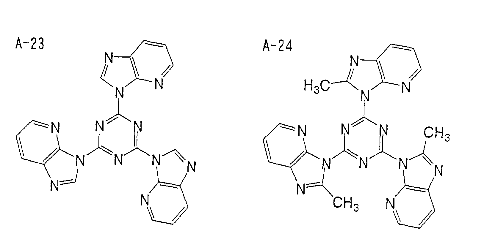


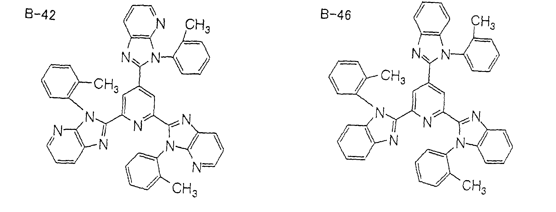


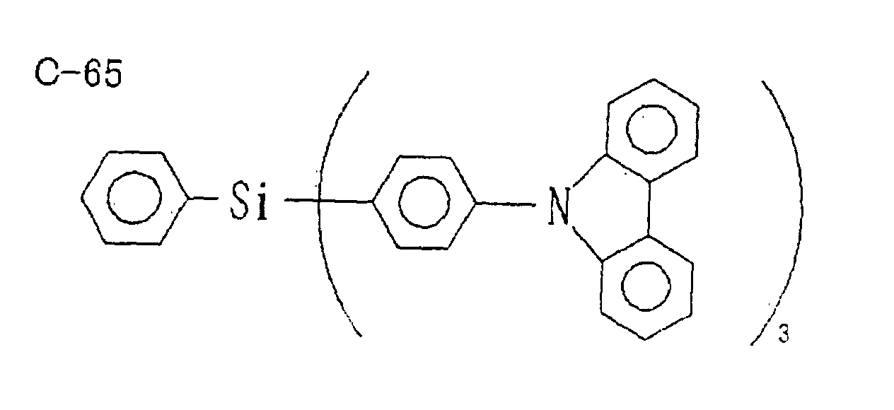


- Next, synthesis examples of the exemplified compounds will be described.
- 3.17 g (8.0 mmol) of 1,3,5-tris(2-aminophenylamino)benzene was dissolved in 50 ml of dimethylacetoamide, and 5 ml (36 mmol) of triethylamine was added thereto under an atmosphere of nitrogen. After cooling to the temperature of 0°C or lower, 2.0 ml (26.4 mmol) of acetylchloride was gently dropped into the mixture so as to maintain the temperature of 0°C or lower. About one hour after the dropping was completed, the temperature was maintained at 0°C or lower, and the temperature was gradually raised and the resulting product was stirred for 5 hours. A reaction solution was poured into 300 ml of water and a solid matter thus deposited was filtered out and washed with water. The obtained solid matter, 1 g of p-toluene sulfonic acid monohydrate, and 100 ml of xylene were heat-refluxed for about 10 hours. The solvent was removed under a reduced pressure, and thereafter, a condensate thus obtained was purified with silica gel column chromatography (eluent: chloroform/methanol = 100/1 (vol/vol)), and then recrystallized with ethylacetate, thereby obtaining 0.24 g of the exemplified compound A-7 (0.51 mmol) (yield: 6.4%).
- 3.69 g (20 mmol) of cyanuric chloride, 8.72 g (66 mmol) of 2-methylbenzimidazole, 41.6 g (180 mmol) of rubidium carbonate, 0.135 g (0.6 mmol) of palladium acetate, 0.44 ml (1.8 mmol) of tri-tert-butylphosphine, and 70 ml of o-xylene were mixed and heated under an atmosphere of nitrogen at 120°C for 6 hours. After cooling to room temperature, a solid matter was filtered out, and washed with chloroform. An organic layer thus formed was washed with water, and thereafter, dried with magnesium sulfuric anhydride, and the solvent was removed under a reduced pressure. The condensate was purified with silica gel column chromatography (eluent: chloroform/methanol = 100/1 (vol/vol)), and thereafter, recrystallized with ethyl acetate to obtain 2.5 g (5.32 mmol) of the exemplified compound A-19 (yield: 27%).
- The aforementioned light emitting material contains at least one compound having a light emission maximum wavelength from an exciton in the blue region. The light emission in the blue region is derived from a transition from the minimum exciton triplet energy (T1) to the ground state.
- In the light emitting element, a material having a high phosphorescence quantum yield is preferably used as the light emitting material. Specifically, a light emitting material having a phosphorescence quantum yield of 70% or more at 20°C and a phosphorescence emission maximum wavelength λmax of 500 nm or less is preferable. A light emitting material having a phosphorescence quantum yield of 80% or more at 20°C and a phosphorescence emission maximum wavelength λmax of 490 nm or less is more preferable. A light emitting material having a phosphorescence quantum yield of 85% or more at 20°C and a phosphorescence emission maximum wavelength λmax of 480 nm or less is still further preferable.
- The above-described light emitting material is a compound contained in a light emitting layer of the light emitting element, or in organic compound layers including the light emitting layer, which compound itself emits light. A transition metal complex is preferable as the light emitting material, and an orthometalated complex is more preferable. Among these complexes, iridium complexes, osmium complexes and platinum complexes are preferable in the point that these complexes have a high phosphorescence quantum yield and further improve the external quantum efficiency of the light emitting element. Iridium complexes and platinum complexes are more preferable, orthometalated iridium complexes are still more preferable, and a compound having a partial structure represented by general formula K-0 (described later) is particularly preferable. Examples of preferred transition metal complexes include compounds described in Japanese Patent Application Nos. 11-370353, 2000-287177, 2000-28178, 2000-299495, 2000-398907, 2001-33684, and 2001-45476.
- The orthometalated complex referred to herein is a generic designation of the group of compounds described in Akio Yamamoto, Yûki Kinzoku Kagaku, Kiso to Ôyô ("Organic Metal Chemistry, Fundamentals and Applications", Shôkabô, 1982), pp. 150 and 232, and in H. Yersin, Photochemistry and Photophysics of Coordination Compounds (New York: Springer-Verlag, 1987), pp. 71-77 and pp. 135-146.
- The light emitting element preferably contains, as the light emitting material, the compound having the partial structure represented by the following general formula K-0 (hereinafter, sometimes referred to as "iridium compound"). Among iridium compounds, a compound having a phosphorescence quantum yield and a phosphorescence emission maximum wavelength λmax that are within the ranges described above is preferred. The general formula K-0 will be described in detail below.
- The light emitting material in the present invention functions in the state of being contained in the light emitting layer of the light emitting element or in a plurality of organic compound layers including the light emitting layer.

- In the general formula K-0, R1 to R7 each independently represents a hydrogen atom or a substituent, provided that, if R2 is a fluorine atom, R3 shall not be a hydrogen atom. Examples of the substituent include groups, which will be described later for R11 in the general formula K-0. R1 in the general formula K-0 is preferably a hydrogen atom, an alkyl group, an aryl group or a heteroaryl group, and more preferably a hydrogen atom. R2 in the general formula K-0 is preferably a hydrogen atom, an alkyl group, an aryl group, a heteroaryl group or a fluorine atom, and more preferably a hydrogen atom, fluorine atom, or alkyl group. R3 in the general formula K-0 is preferably a hydrogen atom, an alkyl group, an aryl group, a heteroaryl group or a fluorine atom, more preferably a hydrogen atom or a fluorine atom, and further preferably a fluorine atom.
- R5 in the general formula K-0 is preferably a hydrogen atom, an alkyl group, a substituted or unsubstituted amino group or an alkoxy group, more preferably a hydrogen atom, alkyl group, or an alkoxy group, and further preferably a hydrogen atom. R4, R6, and R7 are each preferably a hydrogen atom or an alkyl group, and more preferably a hydrogen atom.
- In the general formula K-0, the valence of the iridium atom in the iridium compound is not particularly limited, and is preferably trivalent. The iridium compound may be a so-called single nucleus complex containing one iridium atom and may also be a so-called multinuclei complex containing two or more iridium atoms. Among these, a single nucleus complex containing one iridium atom is preferred. The iridium compound may contain a metallic atom other than iridium, and a compound containing a central metal being only an iridium atom is preferred.
- The iridium compound may have various kinds of ligands in the structure thereof. Examples of the ligand include ligands disclosed in H. Yersin, Photochemistry and Photophysics of Coordination Compounds (New York: Springer-Verlag, 1987) and in Akio Yamamoto, Yûki Kinzoku Kagaku, Kiso to Ôyô ("Organic Metal Chemistry, Fundamentals and Applications", Shôkabô, 1982). The ligand may be either a unidentate ligand or a bidentate ligand. As the ligand, a halogen ligand (preferably a chlorine ligand), a nitrogen-containing heterocyclic ligand (such as phenylpyridine, benzoquinoline, quinolinole, bipyridyl and phenanthroline), a diketone ligand and a carboxylic acid ligand are preferred, and a diketone ligand (such as acetylacetone) is more preferred. The ligand contained in the iridium compound may be of one kind or two or more kinds. The ligand contained in the iridium compound is preferably of one or two kinds, and particularly of one kind. The iridium compound may be either a neutral complex having no electric charge or an anionic complex having a counter salt (such as a chloride ion, a PF6 ion and a ClO4 ion). Among these, a neutral complex is preferred.
- The number of carbon atoms contained in the iridium compound is preferably from 15 to 100, more preferably from 20 to 70, and further preferably from 30 to 60.
- The compound having the partial structure represented by the general formula K-0 is preferably a compound having a partial structure represented by the general formula K-I, or a compound having a partial structure represented by the general formula K-III, and more preferably a compound having a partial structure represented by the general formula K-III. The compound having the partial structure represented by the general formula K-I is preferably an iridium complex represented by the general formula K-II, and more preferably an iridium complex represented by the general formula K-V. The compound having the partial structure represented by the general formula K-III is preferably an iridium complex represented by the general formula K-IV, and more preferably an iridium complex represented by the general formula K-VI.


- Next, the general formula K-I will be described.
- In the general formula K-I, R11 and R12 each independently represents a hydrogen atom or a substituent. Examples of the substituent include an alkyl group (preferably having from 1 to 30 carbon atoms, more preferably having from 1 to 20 carbon atoms, and particularly preferably having from 1 to 10 carbon atoms, such as methyl, ethyl, iso-propyl, tert-butyl, n-octyl, n-decyl, n-hexadecyl, cyclopropyl, cyclopentyl and cyclohexyl), an alkenyl group (preferably having from 2 to 30 carbon atoms, more preferably having from 2 to 20 carbon atoms, and particularly preferably having from 2 to 10 carbon atoms, such as vinyl, allyl, 2-butenyl and 3-pentenyl), an alkynyl group (preferably having from 2 to 30 carbon atoms, more preferably having from 2 to 20 carbon atoms, and particularly preferably having from 2 to 10 carbon atoms, such as propargyl and 3-pentynyl), an aryl group (preferably having from 6 to 30 carbon atoms, more preferably having from 6 to 20 carbon atoms, and particularly preferably having from 6 to 12 carbon atoms, such as phenyl, p-methylphenyl, naphthyl and anthranyl), an amino group (preferably having from 0 to 30 carbon atoms, more preferably having from 0 to 20 carbon atoms, and particularly preferably having from 0 to 10 carbon atoms, such as amino, methylamino, dimethylamino, diethylamino, dibenzylamino, diphenylamino and ditolylamino), an alkoxy group (preferably having from 1 to 30 carbon atoms, more preferably having from 1 to 20 carbon atoms, and particularly preferably having from 1 to 10 carbon atoms, such as methoxy, ethoxy, butoxy and 2-ethylhexyloxy), an aryloxy group (preferably having from 6 to 30 carbon atoms, more preferably having from 6 to 20 carbon atoms, and particularly preferably having from 6 to 12 carbon atoms, such as phenyloxy, 1-naphtyloxy and 2-naphthyloxy), a heteroaryloxy group (preferably having from 1 to 30 carbon atoms, more preferably having from 1 to 20 carbon atoms, and particularly preferably having from 1 to 12 carbon atoms, such as pyridyloxy, pyradyloxy, pyrimidyloxy and quinolyloxy), an acyl group (preferably having from 1 to 30 carbon atoms, more preferably having from 1 to 20 carbon atoms, and particularly preferably having from 1 to 12 carbon atoms, such as acetyl, benzoyl, formyl and pivaloyl), an alkoxycarbonyl group (preferably having from 2 to 30 carbon atoms, more preferably having from 2 to 20 carbon atoms, and particularly preferably having from 2 to 12 carbon atoms, such as methoxycarbonyl and ethoxycarbonyl), an aryloxycarbonyl group (preferably having from 7 to 30 carbon atoms, more preferably having from 7 to 20 carbon atoms, and particularly preferably having from 7 to 12 carbon atoms, such as phenyloxycarbonyl), an acyloxy group (preferably having from 2 to 30 carbon atoms, more preferably from 2 to 20 carbon atoms, and particularly preferably having from 2 to 10 carbon atoms, such as acetoxy and benzoyloxy), an acylamino group (preferably having from 2 to 30 carbon atoms, more preferably having from 2 to 20 carbon atoms, and particularly preferably having from 2 to 10 carbon atoms, such as acetylamino and benzoylamino), an alkoxycarbonylamino group (preferably having from 2 to 30 carbon atoms, more preferably having from 2 to 20 carbon atoms, and particularly preferably having from 2 to 12 carbon atoms, such as methoxycarbonylamino), an aryloxycarbonylamino group (preferably having from 7 to 30 carbon atoms, more preferably having from 7 to 20 carbon atoms, and particularly preferably having from 7 to 12 carbon atoms, such as phenyloxycarbonylamino), a sulfonylamino group (preferably having from 1 to 30 carbon atoms, more preferably having from 1 to 20 carbon atoms, and particularly preferably having from 1 to 12 carbon atoms, such as methanesulfonylamino and benzenesulfonylamino), a sulfamoyl group (preferably having from 0 to 30 carbon atoms, more preferably having from 0 to 20 carbon atoms, and particularly preferably having from 0 to 12 carbon atoms, such as sulfamoyl, methylsulfamoyl, dimethylsulfamoyl and phenylsulfamoyl), a carbamoyl group (preferably having from 1 to 30 carbon atoms, more preferably having from 1 to 20 carbon atoms, and particularly preferably having from 1 to 12 carbon atoms, such as carbamoyl, methylcarbamoyl, diethylcarbamoyl and phenylcarbamoyl), an alkylthio group (preferably having from 1 to 30 carbon atoms, more preferably having from 1 to 20 carbon atoms, and particularly preferably having from 1 to 12 carbon atoms, such as methylthio and ethylthio), an arylthio group (preferably having from 6 to 30 carbon atoms, more preferably having from 6 to 20 carbon atoms, and particularly preferably having from 6 to 12 carbon atoms, such as phenylthio), a heteroarylthio group (preferably having from 1 to 30 carbon atoms, more preferably having from 1 to 20 carbon atoms, and particularly preferably having from 1 to 12 carbon atoms, such as pyridylthio, 2-benzimidazolylthio, 2-benzoxazolylthio and 2-benzthiazolylthio), a sulfonyl group (preferably having from 1 to 30 carbon atoms, more preferably having from 1 to 20 carbon atoms, and particularly preferably having from 1 to 12 carbon atoms, such as mesyl and tosyl) , a sulfinyl group (preferably having from 1 to 30 carbon atoms, more preferably having from 1 to 20 carbon atoms, and particularly preferably having from 1 to 12 carbon atoms, such as methanesulfinyl and benzenesulfinyl), an ureido group (preferably having from 1 to 30 carbon atoms, more preferably having from 1 to 20 carbon atoms, and particularly preferably having from 1 to 12 carbon atoms, such as ureido, methylureido and phenylureido), a phosphoamide group (preferably from 1 to 30 carbon atoms, more preferably from 1 to 20 carbon atoms, particularly preferably from 1 to 12 carbon atoms, such as diethylphosphoamide and phenylphosphoamide), a hydroxyl group, a mercapto group, a halogen atom (such as a fluorine atom, a chlorine atom, a bromine atom and an iodine atom), a cyano group, a sulfo group, a carboxyl group, a nitro group, a hydroxamic acid group, a sulfino group, a hydrazino group, an imino group, a heterocyclic group (such as an aliphatic heterocyclic group and a heteroaryl group, preferably having from 1 to 30 carbon atoms, and more preferably having from 1 to 12 carbon atoms, examples of the hetero atom including a nitrogen atom, an oxygen atom and a sulfur atom, and examples of the heterocyclic group including imidazolyl, pyridyl, quinolyl, furyl, thienyl, piperidyl, morphorino, benzoxazolyl, benzimidazolyl, benzthiazolyl and carbazolyl), and a silyl group (preferably having from 3 to 40 carbon atoms, more preferably from 3 to 30 carbon atoms, and particularly preferably having from 3 to 24 carbon atoms, such as trimethylsilyl and triphenylsilyl). These substituents may further be substituted.
- R11 in the general formula K-I is preferably a hydrogen atom, an alkyl group, an aryl group or a heteroaryl group, and more preferably a hydrogen atom.
- R12 in the general formula K-I is preferably a hydrogen atom, an alkyl group, an aryl group, a heteroaryl group or a fluorine atom, more preferably a hydrogen atom or a fluorine atom, and further preferably a fluorine atom.
- R13, R14, R15, and R16 in the general formula K-I each independently represents a hydrogen or a substituent. Two or more of substituents may be combined with each other to form a cyclic structure. The substituent may be any group of R11. R14 in the general formula K-I is preferably a hydrogen atom, an alkyl group, a substituted or unsubstituted amino group or an alkoxy group, more preferably a hydrogen atom, an alkyl group, or an alkoxy group, and particularly preferably a hydrogen atom.
- R13, R15 and R16 in the general formula K-I are each preferably a hydrogen atom or an alkyl group, and more preferably a hydrogen atom.
- Next, the general formula K-II will be described. In the general formula K-II, R21, R22, R23, R24, R25, and R26 each has the same meaning as R11, R12, R13, R14, R15, and R16 in the general formula K-I, and a preferred embodiment thereof is also the same.
- L21 in the general formula K-II represents a ligand. Examples of the ligand include ligands disclosed in H. Yersin, Photochemistry and Photophysics of Coordination Compounds (Springer-Verlag, 1987) and in Akio Yamamoto, Yûki Kinzoku Kagaku, Kiso to Ôyô ("Organic Metal Chemistry, Fundamentals and Applications", Shôkabô, 1982). As the ligand, a halogen ligand (preferably a chlorine ligand), a nitrogen-containing heterocyclic ligand (such as phenylpyridine, benzoquinoline, quinolinole, bipyridyl and phenanthroline), a diketone ligand, and a carboxylic acid ligand are preferred. A nitrogen-containing heterocyclic ligand and a diketone ligand are more preferred.
- n21 in the general formula K-II represents an integer of 1 to 3, and more preferably 2 or 3. n22 in the general formula K-II represents an integer of 0 to 4, and more preferably 0 or 1.
- Next, the general formula K-III will be described. R31 and R32 in the general formula K-III each independently represents a hydrogen atom or a substituent. The substituent may be any group of R11 in the general formula K-I. R31 in the general formula K-III is preferably a hydrogen atom, an alkyl group, an aryl group, or a heteroaryl group, and more preferably a hydrogen atom. R32 in the general formula K-III is preferably a hydrogen atom, an alkyl group, an aryl group, a heteroaryl group, or a fluorine atom, more preferably a hydrogen atom or a fluorine atom, and further preferably a hydrogen atom.
- R33 to R36 in the general formula K-III each independently represents a hydrogen atom or a substituent. Two or more of substituents may be combined with each other to form a cyclic structure. The substituent may be any group of R11 in the general formula K-I. R34 in the general formula K-III is preferably a hydrogen atom, an alkyl group, a substituted or unsubstituted amino group or an alkoxy group, more preferably a hydrogen atom, an alkyl group, or an alkoxy group, and further preferably a hydrogen atom. R33, R35, and R36 in the general formula K-III are each preferably a hydrogen atom or an alkyl group, and more preferably a hydrogen atom.
- Next, the general formula K-IV will be described.
- In the general formula K-IV, R41, R42, R43, R44, R45, and R46 each has the same meaning as R31, R32, R33, R34, R35, and R36 in the general formula K-III, and a preferred embodiment thereof is also the same. L41 in the general formula K-IV has the same meaning as L21 in the general formula K-II, and a preferred embodiment thereof is also the same. n41 in the general formula K-IV represents an integer of 1 to 3, and preferably 1 or 2. n42 in the general formula K-IV represents an integer of 0 to 4, and preferably 0 or 1.
- Next, the general formula K-V will be described. In the general formula K-V, R53, R54, R55, R56, L51, n51, and n52 each has the same meaning as R23, R24, R25, R26, L21, n21, and n22 in the general formula K-II, and a preferred embodiment thereof is also the same.
- Next, the general formula K-VI will be described. In the general formula K-VI, R63, R64, R65, R66, L61, n61, and n62 each has the same meaning as R43, R44, R45, R46, L41, n41, and n42 in the general formula K-IV, and a preferred embodiment thereof is also the same.
- The iridium compound may be either a so-called low molecular weight compound or a so-called oligomer compound and a so-called polymer compound containing repeating units having the partial structure represented by the general formula K-0 (which preferably contain a weight average molecular weight (polystyrene standard) of from 1,000 to 5,000,000, more preferably from 2,000 to 1,000,000, and further preferably from 3,000 to 100,000). Among these, it is preferable that the iridium compound is a low molecular weight compound.
- Example compounds (K-1) to (K-25) of the iridium compound having the partial structure represented by the general formula K-0 will be described below, but the invention is not limited to the same.


- The compound having the partial structure represented by the general formula K-0 can be synthesized by various methods. For example, the various ligands or a dissociated product thereof and the iridium compound are reacted in the presence of a solvent (such as a halogen-substituted hydrocarbon, an alcohol, an ether and water) or the absence of a solvent, and in the presence of a base (such as various kinds of inorganic and organic bases, e.g., sodium methoxide, t-butoxy potassium, triethylamine and potassium carbonate) or the absence of a base, at room temperature or under heating (in which a method of heating by microwave is also effective as well as ordinary heating). Examples of the starting material include iridium (III) chloride, trisacetylacetonato iridium (III), potassium hexachloroiridate (III), potassium hexachloroiridate (IV) and an analogue thereof.
- The iridium complex represented by the general formula K-II and the iridium complex represented by the general formula K-IV can be utilized as a material for a light-emitting element and can also be used for medical uses, fluorescent whitening agents, photographic materials, UV absorbing materials, laser dyes, dyes for color filters and color conversion filters.
- 1.77 g of 2- (4-fluorophenyl)pyridine, 0.5 g of trisacetylacetonato iridium (III) and 30 ml of glycerol were mixed and then stirred under a nitrogen stream at 200°C for 4 hours. After cooling to room temperature, 200 ml of methanol was added thereto, and a solid matter thus deposited was filtered out. The solid matter was purified with silica gel column chromatography (eluent: chloroform) to obtain 0.5 g of a pale yellow solid matter. The NMR measurement thereof revealed that the resulting compound was the example compound K-1.
- The phosphorescence quantum yield of the resulting example compound K-1 was measured after degassing oxygen (solvent: toluene, concentration: 5.0 × 10⁻⁶ mol/L), and it was 90%. The phosphorescence emission maximum wavelength λmax was 477 nm.

- 3.0 g of 2- (2,4-difluorophenyl)pyridine, 1.3 g of trisacetylacetonato iridium (III) and 50 ml of glycerol were mixed and then stirred under a nitrogen stream at 200°C for 4 hours. After cooling to room temperature, 200 ml of methanol was added thereto, and a solid matter thus deposited was filtered out. The solid matter was purified with silica gel column chromatography (eluent: chloroform) to obtain 0.8 g of a pale yellow solid matter. The NMR measurement thereof revealed that the resulting compound was the example compound K-3.
- The phosphorescence quantum yield of the resulting example compound K-3 was measured after degassing oxygen (solvent: toluene, concentration: 5.0 × 10⁻⁶ mol/L), and it was 70%. The phosphorescence emission maximum wavelength λmax was 470 nm.

- 10 ml of chloroform was added to 0.2 g of compound (a) and 0.07 ml of acetylacetone, and 0.13 ml of methanol solution of sodium methoxide (28 % by weight) was further added thereto and then stirred under a reflux for 6 hours. After cooling to room temperature, 50 ml of chloroform and 50 ml of water were added thereto, and an organic layer was separated. The organic layer was purified with silica gel column chromatography (eluent: chloroform) to obtain 0.1 g of a pale yellow solid matter. The NMR measurement thereof revealed that the resulting compound was the example compound K-9.

- 1.0 g of 2- (2,4-difluorophenyl)-4-methylpyridine, 1.0 g of trisacetylacetonato iridium (III) and 30 ml of glycerol were mixed and then stirred under a nitrogen stream at 200°C for 4 hours. After cooling to room temperature, 200 ml of water was added thereto, and a solid matter thus deposited was filtered out. The solid matter was purified with silica gel column chromatography (eluent: chloroform) to obtain 0.2 g of a pale yellow solid matter. The NMR measurement thereof revealed that the resulting compound was the example compound K-11.

- The aforementioned host material provides a field for the recombination of injected holes and electrons and also has the ability to transfer the energy of an exciton generated by the recombination to the guest. Given as examples of the host material are materials having a carbazole skeleton, materials having a diarylamine skeleton, materials having a pyridine skeleton, materials having a pyrazine skeleton, materials having a triazine skeleton and materials having an arylsilane skeleton.
- In the light emitting element of the present invention, the light emitting layer may be formed by doping the host material with the light emitting material. For example, the light emitting layer may be formed by co-depositing the light emitting material and the host material. The light emitting layer can be formed by utilizing a vacuum deposition method, LB method, ink jet method, printing method, transfer method or coating method (e.g., a spin coating method, casting method, dip coating method, or the like). The use of the aforementioned coating method is advantageous in reducing production costs. However, the coating method conventionally poses the problem that a light emitting element utilizing the above coating method is inferior in emission illuminance and luminance efficiency to those produced by a deposition method or the like. In the light emitting element of the present invention, when the layer disposed adjacent to the light emitting layer is formed of an organic material satisfying the above requirements, the luminance efficiency is improved. Therefore, a light emitting element having good luminance efficiency can be provided at low cost by producing this light emitting element utilizing the coating method.
- In the coating method, a coating solution, in which the light emitting material is dissolved in a solvent, is prepared and the coating solution is applied to a desired position to form the light emitting layer. A resin may be dissolved or dispersed in the solvent together with the light emitting material to prepare the coating solution. Given as examples of the resin are polyvinyl chloride, polycarbonate, polystyrene, polymethyl methacrylate, polybutyl methacrylate, polyester, polysulfone, polyphenylene oxide, polybutadiene, poly(N-vinylcarbazole), hydrocarbon resins, ketone resins, phenoxy resins, polyamide, ethyl cellulose, polyvinyl acetate, ABS resins, polyurethane, melamine resins, unsaturated polyester resins, alkyd resins, epoxy resins, silicone resins, and the like.
- A film thickness of the light emitting layer is generally preferably 1 nm to 5µm, more preferably 5 nm to 1µm and still more preferably 10 nm to 500 nm, though no particular limitation is imposed on the thickness.
- In the light emitting layer, the weight ratio of the light emitting material to the host material is generally from 0.1 by weight to 20 % by weight, preferably from 0.5 % by weight to 15 % by weight, and more preferably from 1.0 % by weight to 10 % by weight.
- Materials used for the hole injecting layer and hole transporting layer have the ability to inject holes from an anode and to transport holes, respectively. These materials preferably have the ability to block electrons injected from a cathode in addition to the above abilities.
- Specific examples of the hole transporting material and hole injecting material include carbazole derivatives, imidazole derivatives, triazole derivatives, oxazole derivatives, oxadiazole derivatives, polyarylalkane derivatives, pyrazoline derivatives, pyrazolone derivatives, phenylenediamine derivatives, arylamine derivatives, amino substituted calcon derivatives, styrylanthracene derivatives, fluorenone derivatives, hydrazone derivatives, stilbene derivatives, silazane derivatives, aromatic tertiary amine compounds, styrylamine derivatives, aromatic dimethylidyne derivatives, porphyrin derivatives, polysilane derivatives, poly(N-vinylcarbazole) derivatives, aniline type copolymers, thiophene oligomers, electroconductive polymers and oligomers such as polythiophene, organic silane derivatives and organic phosphine derivatives.
- The hole injecting layer and hole transporting layer may have either a monolayer structure comprising one or two types selected from the above materials or a multilayer structure comprising plural layers having the same compositions or different compositions.
- In a case where the hole transporting layer or the hole injecting layer is disposed adjacent to the light emitting layer, the T1 level of the hole transporting material or hole injecting material is preferably higher than the T1 level of the light emitting material. The T1 level of the hole transporting material or hole injecting material is preferably more than 1.05 times and more preferably more than 1.1 times the T1 level of the light emitting material. The T1 level of the hole transporting material or hole injecting material is preferably from 68 kcal/mol (284.9 kJ/mol) to 90 kcal/mol (377.1 kJ/mol), more preferably from 69 kcal/mol (289.1 kJ/mol) to 85 kcal/mol (356.2 kJ/mol) and still more preferably from 70 kcal/mol (293.3 kJ/mol) to 80 kcal/mol (335.2 kJ/mol).
- In a case where the hole transporting layer or the hole injecting layer is disposed adjacent to the light emitting layer and has a multilayer structure, the T1 level of each of all hole transporting materials and hole injecting materials contained in the multilayer is preferably higher than the T1 level of the light emitting, material.
- Examples of a method of forming the hole injecting layer and the hole transporting layer include a vacuum deposition method, LB method, ink jet method, printing method, coating method (e.g., a spin coating method, casting method, dip coating method and the like), and transfer method similarly to the method of forming the light emitting layer. When a coating solution to be used for the coating method is prepared, a resin may be used. Examples of the resin include the same resins that are exemplified as being usable for the preparation of the coating solution used in the formation of the light emitting layer.
- A film thickness of each of the hole injecting layer and the hole transporting layer is preferably 1 nm to 5 µm, more preferably 5 nm to 1µm and still more preferably 10 nm to 500 nm in general, though there is no particular limitation to the thickness.
- Materials used for the electron injecting layer and the electron transporting layer have the ability to inject electrons from a cathode and to transport electrons, respectively. These materials preferably have the ability to block holes injected from an anode in addition to the above abilities.
- Specific examples of the electron injecting material and electron transporting material include various metal complexes represented by metal complexes of imidazole derivatives, triazole derivatives, triazine derivatives, oxazole derivatives, oxadiazole derivatives, fluorenone derivatives, anthraquinodimethane derivatives, anthrone derivatives, diphenylquinone derivatives, thiopyranedioxide derivatives, carbodiimide derivatives, fluorenylidenemethane derivatives, distyrylpyrazine derivatives, cyclic tetracarboxylic acid of aromatic compound such as perylene and naphthalene, phthalocyanine derivatives or 8-quinolinol derivatives and by metal complexes containing metal phthalocyanine, benzoxazole or benzothiazole as a ligand and organosilane derivatives. The electron injecting layer and electron transporting layer may have either a monolayer structure comprising one or two types selected from the above materials or a multilayer structure comprising plural layers having the same compositions or different compositions.
- In a case where the electron transporting layer or the electron injecting layer is disposed adjacent to the light emitting layer, the T1 level of the electron transporting material or electron injecting material is preferably higher than the T1 level of the light emitting material. The T1 level of the electron transporting material or electron injecting material is preferably more than 1.05 times and more preferably more than 1.1 times the T1 level of the light emitting material. The T1 level of the electron transporting material or electron injecting material is preferably from 68 kcal/mol (284.9 kJ/mol) to 90 kcal/mol (377.1 kJ/mol), more preferably from 69 kcal/mol (289.1 kJ/mol) to 85 kcal/mol (356.2 kJ/mol) and still more preferably from 70 kcal/mol (293.3 kJ/mol) to 80 kcal/mol (335.2 kJ/mol).
- In a case where the electron transporting layer or the electron injecting layer is disposed adjacent to the light emitting layer and has a multilayer structure, the T1 level of each of all electron transporting materials and electron injecting materials contained in the multilayer is preferably higher than the T1 level of the light emitting material.
- Examples of a method of forming the electron injecting layer and the electron transporting layer include a vacuum deposition method, LB method, ink jet method, printing method, coating method (e.g., a spin coating method, casting method, dip coating method and the like), and transfer method similarly to the method of forming the light emitting layer. When a coating solution to be used for the coating method is prepared, a resin may be used. Examples of the resin include the same resins that are exemplified as being usable for the preparation of the coating solution used in the formation of the light emitting layer.
- A film thickness of each of the electron injecting layer and the electron transporting layer is preferably 1 nm to 5µm, more preferably 5 nm to 1µm and still more preferably 10 nm to 500 nm in general, though there is no particular limitation to the thickness.
- Materials for the protective layer may be those having the ability to prevent the intrusion of a material, such as water and oxygen promoting elemental deterioration, into the element. Specific examples of such a material include metals such as In, Sn, Pb, Au, Cu, Ag, Al, Ti and Ni, metal oxides such as MgO, SiO, SiO2, Al2O3, GeO, NiO, CaO, BaO, Fe2O3, Y2O3 and TiO2, nitrides such as SiNx and SiNxOy, metal fluorides such as MgF2, LiF, AlF3 and CaF2, polyethylene, polypropylene, polymethyl methacrylate, polyimide, polyurea, polytetrafluoroethylene, polychlorotrifluoroethylene, polydichlorodifluoroethylene, copolymers of chlorotrifluoroethylene and dichlorodifluoroethylene, copolymers obtained by copolymerizing tetrafluoroethylene and a monomer mixture containing at least one comonomer, fluorine-containing copolymers having a cyclic structure on a copolymer principal chain, water-absorbable materials having an absorption coefficient of 1% or more and moisture proof materials having an absorption coefficient of 0.1% or less.
- No particular limitation is imposed on a method of forming the protective layer. As the method, for example, a vacuum deposition method, sputtering method, reactive sputtering method, MBE (molecular beam epitaxy) method, cluster ion beam method, ion plating method, plasma polymerization method (high frequency excitation ion plating method), plasma CVD method, laser CVD method, thermal CVD method, gas source CVD method, coating method, ink jet method, printing method, and transfer method may be applied.
- Materials constituting the anode serves to supply holes to the hole injecting layer, hole transporting layer and light emitting layer. As the material, a metal, alloy, metal oxide, electroconductive compound or a mixture of these materials may be used. Preferable materials are those having a working function of 4 eV or more. Specific examples of these materials include conductive metal oxides such as tin oxide, zinc oxide, indium oxide, indium tin oxide (ITO), metals such as gold, silver, chromium and nickel, mixtures or laminates of these metals and conductive metal oxides, inorganic conductive materials such as copper iodide and copper sulfide, organic conductive materials such as polyaniline, polythiophene and polypyrrole and laminates of these materials and ITO. Among these materials, conductive metal oxides are preferable and ITO is particularly preferable in view of productivity, high conductivity and transparency.
- Although a film thickness of the anode may be selected optionally according to the type of material, it is in a range preferably from 10 nm to 5µm, more preferably from 50 nm to 1µm and still more preferably from 100 nm to 500 nm in general.
- As the anode, an electrode obtained by forming a layer on soda lime glass, non-alkali glass and a transparent resin substrate is usually used. When glass is used as the substrate, non-alkali glass is preferably used as the glass material to decrease the elution of ions from the glass. Also, when soda lime glass is used, glass which is coated with silica as a barrier is preferably used. Although no particular limitation is imposed on the thickness of the substrate as far as it is enough to maintain the mechanical strength, a substrate having a thickness of generally 0.2 mm or more and preferably 0.7 mm or more is used when glass is used. For the formation of the anode, various methods are used according to the type of material. In a case of, for example, ITO, a film is formed using a method such as an electron beam method, sputtering method, resistance heating deposition method, chemical reaction method (sol-gel method) and method of applying a dispersion of ITO.
- The driving voltage for the light emitting element can be reduced and the luminance efficiency can be raised by performing treatments such as washing and other treatments of the anode. For example, in a case of ITO, UV-ozone treatment and plasma treatment are effective.
- A material constituting the cathode serves to supply electrons to the electron injecting layer, electron transporting layer, light emitting layer and the like and is selected in consideration of adhesion to the layers, such as the electron injecting layer, electron transporting layer and light emitting layer, disposed adjacent thereto, ionizing potential and stability. As the material of the cathode, a metal, alloy, metal oxide, electroconductive compound or mixture of these materials may be used. Specific examples include alkali metals (e.g., Li, Na, K, Cs and the like) or fluorides or oxides of these compounds, alkali earth metals (e.g., Mg and Ca) or fluorides or oxides of these compounds, gold, silver, lead, aluminum, sodium-potassium alloys or mixtures of this alloy and other metal, lithium-aluminum alloys or mixtures of this alloy and other metal, magnesium-silver alloys or mixtures of this alloy and other metal and rare earth metals such as indium and ytterbium. Materials having a working function of 4 eV or less are preferable and aluminum, lithium-aluminum alloys or mixtures of this alloy and other metal and magnesium-silver alloys or mixtures of this alloy and other metal are more preferable.
- Although a film thickness of the cathode may be optionally selected, the cathode has a film thickness ranging preferably from 10 nm to 5µm, more preferably from 50 nm to 1µm and more preferably 100 nm to 1µm in general.
- The cathode is formed using a method such as an electron beam method, sputtering method, resistance heating deposition method and coating method. A metal can be deposited singly and two or more metal components may be deposited simultaneously. Moreover, plural metals may be deposited at the same time to form an alloy electrode. Also, an alloy prepared in advance may be deposited.
- It is preferable that the sheet resistance of each of the anode and the cathode be lower and preferably several hundreds Ω/□ or less.
- The light emitting element of the present invention may be served to applications in wide fields such as display elements, displays, back-up lights, electrophotographs, illumination light sources, recording light sources, reading light sources, beacons, signboards, interiors, and optical communication devices.
- The present invention will be explained in more detail by way of examples, which, however, are not intended to be limiting of the present invention.
- An ITO substrate which was washed was placed in an evaporating apparatus and α-NPD(N,N'-diphenyl-N,N'-di(α -naphthyl)-benzidine) was deposited on the substrate in a thickness of 50 nm. CBP (biscarbazolylbenzidine) and the exemplified compound K-1 were co-deposited thereon in a ratio of 17:1 in a thickness of 36 nm. The exemplified compound B-40 was further deposited thereon in a thickness of 24 nm. A patterned mask (the emission area was designed to be 4 mm×5 mm) was placed on the organic thin film to co-deposit magnesium/silver (10:1) in a thickness of 250 nm. Thereafter, silver was deposited in a thickness of 300 nm to produce a light emitting element.
- A light emitting element was produced in the same manner as in Example 1 except that the exemplified compound A-10 was used in place of CBP in the manufacturing of the light emitting element of Example 1.
- A light emitting element was produced in the same manner as in Example 1 except that TPD(N,N'-diphenyl-N,N'-di(m-tolyl)-benzidine) was used in place of α-NPD in the manufacturing of the light emitting element of Example 1.
- A light emitting element was produced in the same manner as in Example 2 except that TPD was used in place of α-NPD in the manufacturing of the light emitting element of Example 2.
- A light emitting element was produced in the same manner as in Example 4 except that the exemplified compound D-46 was used in place of the exemplified compound A-10 in the manufacturing of the light emitting element of Example 4.
- A light emitting element was produced in the same manner as in Example 4 except that the exemplified compound C-71 was used in place of the exemplified compound A-10 in the manufacturing of the light emitting element of Example 4.
- A light emitting element was produced in the same manner as in Example 3 except that the exemplified compound K-3 was used in place of the exemplified compound K-1 in the manufacturing of the light emitting element of Example 3.
- A light emitting element was produced in the same manner as in Example 4 except that the exemplified compound K-3 was used in place of the exemplified compound K-1 in the manufacturing of the light emitting element of Example 4.
- A light emitting element was produced in such a manner that in the manufacturing of the light emitting element of Example 4, the exemplified compound A-19 was used in place of the exemplified compound B-40 to form an organic thin film, and a pattern mask (the emission area was designed to be 4 mm×5 mm) was placed on the organic thin film to deposit lithium fluoride in a thickness of 3 nm, and thereafter, aluminum was deposited in a thickness of 400 nm.
- A light emitting element was produced in the same manner as in Example 9 except that the exemplified compound K-3 was used in place of the exemplified compound K-1 in the manufacturing of the light emitting element of Example 9.
- A light emitting element was produced in the same manner as in Example 1 except that TPD was used in place of CBP in the manufacturing of the light emitting element of Example 1.
- A light emitting element was produced in the same manner as in Comparative Example 1 except that TPD was used in place of α-NPD and the exemplified compound K-3 was used in place of the exemplified example K-1 in the manufacturing of the light emitting element of Comparative Example 1.
- Respective constitutional formulae of α-NPD, CBP, and TPD used in Examples and Comparative Examples are shown below.


- The minimum excitation triplet energy level T1 of each of CBP, exemplified compounds A-10, D-46, and C-71, TPD, α-NPD, exemplified compounds K-1, K-3, B-40, and A-19, which were used in Examples and Comparative Examples was measured. Specifically, the phosphorescence spectrum of each material was measured (10µmol/l EPA (diethyl ether: isopentane: isopropyl alcohol = 5:5:2 (volume ratio)) solution, 77K, quartz cell, FLUOROLOGII manufactured by SPEX) to determine the T1 level from the beginning of the wavelength on the short wavelength side of the phosphorescence spectrum.
- A fixed d.c. voltage was applied to each of the light emitting elements obtained in Examples and Comparative Examples by using Source Measure Unit 2400 manufactured by Toyo Technica, making each element emit light to measure the luminance by using a luminance meter BM-8 manufactured by Topcon and the light emission wavelength and CIE chromaticity coordinate by using a Spectrum Analizer PMA-11 manufactured by Hamamatsu Photonics.
- The results of each measurement are shown in Table 1 below.

- As is clear from the results shown in Table 1, it is found that the light emitting element in which the T1 level of the host material is higher than the T1 level of the light emitting material could emit light with high efficiency. Further, it was also found that when the T1 level of the layer adjacent to the light emitting layer is higher than the T1 level of the light emitting material, emission of light with higher efficiency becomes possible. Particularly, in a case of the light emitting material which emitted in the blue region, emission with higher efficiency can be attained when the T1 level of the host is higher than 70 kcal/mol (293.3 kJ/mol).
- Similarly, also in applying the coating method to produce the light emitting element, the T1 level of the material used to form the layer containing the light emitting material and/or the layer adjacent to the light emitting layer is made higher than the T1 level of the light emitting material. This makes it possible to produce a light emitting element which can emit light with high efficiency. Also, the T1 level of the material used to form the layer containing the light emitting material and/or the layer adjacent to the light emitting layer is made higher than 70 kcal/mol (293.3 kJ/mol) or more. This makes it possible to produce a light emitting element which can emit light with higher efficiency.
- A washed ITO substrate was placed in an evaporating apparatus and TPD was deposited on the substrate in a thickness of 50 nm. CBP (biscarbazolylbenzidine) and the compound R-1 were co-deposited thereon in a ratio of 1:17 in a thickness of 30 nm. The exemplified compound A-10 and exemplified compound K-3 were further co-deposited thereon in a ratio of 1:17 in a thickness of 2 nm, and the exemplified compound A-19 was still further deposited thereon in a thickness of 36 nm. A patterend mask (the emission area was designed to be 4 mm×5 mm) was placed on the organic thin film to deposit lithium fluoride in a thickness of 3 nm. Thereafter, aluminum was deposited in a thickness of 400 nm to produce a light emitting element.

- A fixed d.c. voltage was applied to the light emitting element obtained in Example 11 by using Source Measure Unit 2400 manufactured by Toyo Technica, making each element emit light to measure the illuminance by using a luminance meter BM-8 manufactured by Topcon and the light emission wavelength and CIE chromaticity coordinate by using a Spectrum Analizer PMA-11 manufactured by Hamamatsu Photonics. As a result, white light emission having chromaticity coordinates (x,y)=(0.35, 0.33) was obtained, the maximum luminance was 75000 cd/m2 and the external quantum efficiency was 15.4 %.
- From the results of Example 11, the light emitting element using the compounds of the present invention can emit light with a high efficiency exceeding 15% even in a white light emitting element having conventionally emitted light with lower efficiency, and a light emitting element which can emit light of white having excellent color purity can be produced.
- According to the present invention, it is possible to provide a light emitting element which can emit light in the blue region with high luminance efficiency, and a light emitting element which can emit light of white of high color purity with high luminance efficiency.
Claims (14)
- A light emitting element comprising at least a light emitting layer containing a light emitting material and a host material and having a light emission maximum wavelength of 500 nm or less wherein the minimum excitation triplet energy level of said host material is higher than the minimum excitation triplet energy level of said light emitting material.
- A light emitting element according to claim 1, wherein the minimum excitation triplet energy level of said host material is from 1.05 times to 1.38 times the minimum excitation triplet energy level of said light emitting material.
- A light emitting element according to claim 1 or 2, wherein the minimum excitation triplet energy level of said host material is from 68 kcal/mol to 90 kcal/mol.
- A light emitting element according to any of claims 1 to 3, further comprising a layer which is disposed adjacent to said light emitting layer and contains an organic material, wherein the minimum excitation triplet energy level of said organic material is higher than the minimum excitation triplet energy level of each of materials which constitute said light emitting layer.
- A light emitting element according to claim 4, wherein the minimum excitation triplet energy level of said organic material contained in the layer which is disposed adjacent to the light emitting layer is from 1.05 times to 1.38 times the minimum excitation triplet energy level of each of the materials which constitute said light emitting layer.
- A light emitting element according to claim 4 or 5, wherein the minimum excitation triplet energy level of said organic material contained in the layer which is disposed adjacent to the light emitting layer is from 68 kcal/mol to 90 kcal/mol.
- A light emitting element according to any of claims 1 to 6, wherein said host material is a compound represented by the following general formula (I):
L1―(Q1)n1 - A light emitting element according to any of claims 4 to 7, wherein said organic material contained in the layer which is disposed adjacent to said light emitting layer is a compound represented by the following general formula (II):
L2―(Q2)n2 - An azole compound represented by the following general formula (A):wherein RA1, RA2, and RA3 each represent a hydrogen atom or an aliphatic hydrocarbon group; RA4, RA5, and RA6 each represent a substituent; nA1, nA2, and nA3 each represents an integer of 0 to 3; XA1, XA2, and XA3 each represent a nitrogen atom or C-RX (RX represents a hydrogen atom or a substituent) ; and YA1, YA2, and YA3 each represent a nitrogen atom or C-RYX (RYX represents a hydrogen atom or a substituent).

- A light emitting element according to any of claims 4 to 8, wherein said organic material contained in the layer which is disposed adjacent to the light emitting layer is the azole compound represented by the general formula (A) according to claim 9.
- A light emitting element according to claim 4, wherein the light emitting layer is held between a pair of electrodes.
- A light emitting element according to claim 1 or 2, wherein the light emitting material is a transition metal complex.
- A light emitting element according to claim 1 or 2, wherein the light emitting layer comprises 0.1 % by weight to 20 % by weight of the light emitting material with respect to a weight of the host material.
- A light emitting element according to claim 1 or 2, wherein the light emitting layer have a thickness of from 1 nm to 5µm.
Priority Applications (1)
| Application Number | Priority Date | Filing Date | Title |
|---|---|---|---|
| EP10006305A EP2224790B1 (en) | 2000-07-17 | 2001-07-17 | Light emitting element and azole compound |
Applications Claiming Priority (2)
| Application Number | Priority Date | Filing Date | Title |
|---|---|---|---|
| JP2000216339 | 2000-07-17 | ||
| JP2000216339 | 2000-07-17 |
Related Child Applications (1)
| Application Number | Title | Priority Date | Filing Date |
|---|---|---|---|
| EP10006305.6 Division-Into | 2010-06-17 |
Publications (3)
| Publication Number | Publication Date |
|---|---|
| EP1175128A2 true EP1175128A2 (en) | 2002-01-23 |
| EP1175128A3 EP1175128A3 (en) | 2002-07-31 |
| EP1175128B1 EP1175128B1 (en) | 2010-09-22 |
Family
ID=18711620
Family Applications (2)
| Application Number | Title | Priority Date | Filing Date |
|---|---|---|---|
| EP01117288A Expired - Lifetime EP1175128B1 (en) | 2000-07-17 | 2001-07-17 | Light emitting element and azole compound |
| EP10006305A Expired - Lifetime EP2224790B1 (en) | 2000-07-17 | 2001-07-17 | Light emitting element and azole compound |
Family Applications After (1)
| Application Number | Title | Priority Date | Filing Date |
|---|---|---|---|
| EP10006305A Expired - Lifetime EP2224790B1 (en) | 2000-07-17 | 2001-07-17 | Light emitting element and azole compound |
Country Status (4)
| Country | Link |
|---|---|
| US (3) | US6962755B2 (en) |
| EP (2) | EP1175128B1 (en) |
| AT (1) | ATE482476T1 (en) |
| DE (1) | DE60143106D1 (en) |
Cited By (35)
| Publication number | Priority date | Publication date | Assignee | Title |
|---|---|---|---|---|
| EP1191613A2 (en) * | 2000-09-26 | 2002-03-27 | Canon Kabushiki Kaisha | Luminescence device, display apparatus and metal coordination compound |
| WO2002044189A1 (en) | 2000-11-30 | 2002-06-06 | Canon Kabushiki Kaisha | Luminescent element and display |
| WO2002060910A1 (en) * | 2001-02-01 | 2002-08-08 | Covion Organic Semiconductors Gmbh | Method for the production of highly pure, tris-ortho-metalated organo-iridium compounds |
| EP1239526A2 (en) * | 2001-03-08 | 2002-09-11 | Canon Kabushiki Kaisha | Metal coordination compound, luminescene device and display apparatus |
| EP1310522A1 (en) * | 2000-06-27 | 2003-05-14 | Daikin Industries, Ltd. | Crosslinkable elastomer composition |
| WO2003063555A1 (en) * | 2001-12-26 | 2003-07-31 | E. I. Du Pont De Nemours And Company | Electroluminescent iridium compounds wiht fluorinated phenylpyridines, phenylpyrimidines, and phenylquinolines and devices made with such compounds |
| EP1349435A1 (en) * | 2000-11-30 | 2003-10-01 | Canon Kabushiki Kaisha | Luminescent element and display |
| WO2003084972A1 (en) * | 2002-04-05 | 2003-10-16 | Covion Organic Semiconductors Gmbh | Rhodium complexes and iridium complexes |
| US6670645B2 (en) | 2000-06-30 | 2003-12-30 | E. I. Du Pont De Nemours And Company | Electroluminescent iridium compounds with fluorinated phenylpyridines, phenylpyrimidines, and phenylquinolines and devices made with such compounds |
| WO2004101707A1 (en) * | 2003-05-16 | 2004-11-25 | Isis Innovation Limited | Organic phosphorescent material and organic optoelectronic device |
| WO2005029606A2 (en) * | 2003-09-19 | 2005-03-31 | Fuji Photo Film Co., Ltd. | Organic electroluminescent device |
| WO2005075597A2 (en) * | 2004-01-30 | 2005-08-18 | E.I. Dupont De Nemours And Company | Electroluminescent iridium compounds with fluorinated phenylpyridine ligands, and devices made with such compounds |
| US6946688B2 (en) | 2000-06-30 | 2005-09-20 | E. I. Du Pont De Nemours And Company | Electroluminescent iridium compounds with fluorinated phenylpyridines, phenylpyrimidines, and phenylquinolines and devices made with such compounds |
| EP1576860A1 (en) * | 2002-12-27 | 2005-09-21 | Fuji Photo Film Co., Ltd. | Organic electroluminescent device |
| US6979739B2 (en) | 2000-06-30 | 2005-12-27 | E. I. Du Pont De Nemours And Company | Electroluminescent iridium compounds with fluorinated phenylpyridines, phenylpyrimidines, and phenylquinolines and devices made with such compounds |
| US7125998B2 (en) | 2001-02-24 | 2006-10-24 | Merck Patent Gmbh | Rhodium and iridium complexes |
| US7132681B2 (en) | 2000-06-30 | 2006-11-07 | E. I. Du Pont De Nemours And Company | Electroluminescent iridium compounds with fluorinated phenylpyridines, phenylpyrimidines, and phenylquinolines and devices made with such compounds |
| US7166368B2 (en) | 2001-11-07 | 2007-01-23 | E. I. Du Pont De Nemours And Company | Electroluminescent platinum compounds and devices made with such compounds |
| US7250512B2 (en) | 2001-11-07 | 2007-07-31 | E. I. Du Pont De Nemours And Company | Electroluminescent iridium compounds having red-orange or red emission and devices made with such compounds |
| US7320833B2 (en) | 2001-11-07 | 2008-01-22 | E.I. Du Pont De Nemours And Company | Electroluminescent platinum compounds and devices made with such compounds |
| CN100383150C (en) * | 2003-05-05 | 2008-04-23 | 巴斯福股份公司 | Method for producing tris-ortho-metallated complexes and use of such complexes in OLEDs |
| KR100871275B1 (en) | 2008-08-27 | 2008-11-28 | 이 아이 듀폰 디 네모아 앤드 캄파니 | Electroluminescent iridium compounds with fluorinated phenylpyridines and devices made with such compounds |
| US7473575B2 (en) | 2001-11-27 | 2009-01-06 | Semiconductor Energy Laboratory Co., Ltd. | Light emitting device |
| CN100460480C (en) * | 2003-09-29 | 2009-02-11 | 新日铁化学株式会社 | Organic electroluminescent device |
| EP2169028A2 (en) | 2002-03-22 | 2010-03-31 | Idemitsu Kosan Co., Ltd. | Material for organic electroluminescent devices and organic electroluminescent devices made by using the same |
| US7737624B2 (en) | 2003-08-04 | 2010-06-15 | Fujifilm Corporation | Organic electroluminescent device |
| US7816016B1 (en) | 2003-02-13 | 2010-10-19 | E. I. Du Pont De Nemours And Company | Electroluminescent iridium compounds and devices made therefrom |
| CN101863914A (en) * | 2010-05-28 | 2010-10-20 | 武汉大学 | Phosphorescent light body material and application |
| US8379736B2 (en) | 2003-05-30 | 2013-02-19 | Intellectual Ventures Holding 73 Llc | Ultra-wideband communication system and method |
| US8383932B2 (en) | 2007-10-17 | 2013-02-26 | Cheil Industries, Inc. | Compound for organic photoelectric device and organic photoelectric device including the same |
| EP2811524A1 (en) * | 2013-06-05 | 2014-12-10 | Cambridge Display Technology Limited | Organic light-emitting device |
| EP2770036B1 (en) * | 2002-03-15 | 2017-12-20 | Idemitsu Kosan Co., Ltd | Material for organic electroluminescent devices and organic electroluminescent devices made by using the same |
| EP3855519A3 (en) * | 2004-07-07 | 2021-09-22 | Universal Display Corporation | Stable and efficient electroluminescent materials |
| US11183644B2 (en) | 2012-04-20 | 2021-11-23 | Semiconductor Energy Laboratory Co., Ltd. | Light-emitting element, light-emitting device, electronic appliance, and lighting device |
| US11569466B2 (en) | 2016-07-28 | 2023-01-31 | Semiconductor Energy Laboratory Co., Ltd. | Light-emitting element, light-emitting device, electronic device, and lighting device |
Families Citing this family (81)
| Publication number | Priority date | Publication date | Assignee | Title |
|---|---|---|---|---|
| US7306856B2 (en) * | 2000-07-17 | 2007-12-11 | Fujifilm Corporation | Light-emitting element and iridium complex |
| DE60143106D1 (en) * | 2000-07-17 | 2010-11-04 | Fujifilm Corp | Light-emitting element and azole compound |
| JP4040249B2 (en) * | 2000-11-16 | 2008-01-30 | 富士フイルム株式会社 | Light emitting element |
| SG115435A1 (en) * | 2000-12-28 | 2005-10-28 | Semiconductor Energy Lab | Luminescent device |
| US6855438B2 (en) | 2001-06-15 | 2005-02-15 | Konica Corporation | Organic electroluminescent element and full color display |
| JP4003824B2 (en) | 2001-07-11 | 2007-11-07 | 富士フイルム株式会社 | Light emitting element |
| US7037598B2 (en) * | 2001-08-07 | 2006-05-02 | Fuji Photo Film Co., Ltd. | Light-emitting element and novel iridium complexes |
| CN100502087C (en) * | 2002-06-06 | 2009-06-17 | 西巴特殊化学品控股有限公司 | Electroluminescent device |
| WO2004016711A1 (en) | 2002-08-16 | 2004-02-26 | The University Of Southern California | Organic light emitting materials and devices |
| US6916554B2 (en) | 2002-11-06 | 2005-07-12 | The University Of Southern California | Organic light emitting materials and devices |
| JPWO2004034751A1 (en) | 2002-10-09 | 2006-02-09 | 出光興産株式会社 | Organic electroluminescence device |
| BR0315894A (en) * | 2002-10-30 | 2005-10-04 | Ciba Sc Holding Ag | Electroluminescent device |
| US9923148B2 (en) | 2002-10-30 | 2018-03-20 | Udc Ireland Limited | Electroluminescent device |
| US20060078757A1 (en) * | 2002-12-13 | 2006-04-13 | Koninklijke Philips Electronics, N.V. | Organic electroluminescent component with triplet emitter complex |
| US20060180806A1 (en) * | 2003-01-24 | 2006-08-17 | Takashi Arakane | Organic electroluminescence device |
| WO2004080975A1 (en) * | 2003-03-13 | 2004-09-23 | Idemitsu Kosan Co., Ltd. | Nitrogen-containing heterocycle derivative and organic electroluminescent element using the same |
| US20040209116A1 (en) * | 2003-04-21 | 2004-10-21 | Xiaofan Ren | Organic light emitting devices with wide gap host materials |
| WO2005004251A1 (en) * | 2003-07-07 | 2005-01-13 | Philips Intellectual Property & Standards Gmbh | Multifluorinated conductor material for leds for improving the light outcoupling |
| JP4635528B2 (en) * | 2003-09-12 | 2011-02-23 | 住友化学株式会社 | Luminescent material and light emitting device using the same |
| KR100522697B1 (en) * | 2003-09-22 | 2005-10-20 | 삼성에스디아이 주식회사 | 4,4'-Bis(carbazol-9-yl)-biphenyl based silicone compound and organic electroluminescence display device |
| US8048535B2 (en) * | 2003-09-24 | 2011-11-01 | Fujifiilm Corporation | Electroluminescent device |
| KR100553752B1 (en) * | 2003-10-13 | 2006-02-20 | 삼성에스디아이 주식회사 | Imidazole ring containing compound and organic electroluminescence display device |
| US7074502B2 (en) * | 2003-12-05 | 2006-07-11 | Eastman Kodak Company | Organic element for electroluminescent devices |
| US20050164031A1 (en) * | 2004-01-26 | 2005-07-28 | Thompson Mark E. | Dual emitting dyads of heavy metal complexes as broad band emitters for organic LEDs |
| JP4351935B2 (en) * | 2004-03-10 | 2009-10-28 | 富士フイルム株式会社 | Organic electroluminescence device |
| WO2005091381A1 (en) * | 2004-03-22 | 2005-09-29 | Fuji Photo Film Co., Ltd. | Photodetector |
| US7527878B2 (en) * | 2004-03-26 | 2009-05-05 | Fujifilm Corporation | Organic electroluminescence element and silicon compound |
| JP2005285470A (en) * | 2004-03-29 | 2005-10-13 | Sanyo Electric Co Ltd | Organic electroluminescent device |
| JP4869565B2 (en) * | 2004-04-23 | 2012-02-08 | 富士フイルム株式会社 | Organic electroluminescence device |
| DE102004023277A1 (en) * | 2004-05-11 | 2005-12-01 | Covion Organic Semiconductors Gmbh | New material mixtures for electroluminescence |
| EP1750487A4 (en) * | 2004-05-14 | 2008-12-17 | Idemitsu Kosan Co | Organic electroluminescent device |
| WO2006034474A2 (en) * | 2004-09-23 | 2006-03-30 | Reddy Us Therapeutics, Inc. | Novel pyridine compounds, process for their preparation and compositions containing them |
| US7803468B2 (en) * | 2004-09-29 | 2010-09-28 | Fujifilm Corporation | Organic electroluminescent element |
| JP5087207B2 (en) * | 2004-09-29 | 2012-12-05 | 富士フイルム株式会社 | Photoelectric conversion device and imaging device |
| TWI260340B (en) * | 2004-11-26 | 2006-08-21 | Au Optronics Corp | Organic electroluminescent device |
| GB0427266D0 (en) * | 2004-12-13 | 2005-01-12 | Cambridge Display Tech Ltd | Phosphorescent OLED |
| US20060134464A1 (en) * | 2004-12-22 | 2006-06-22 | Fuji Photo Film Co. Ltd | Organic electroluminescent element |
| JP4989881B2 (en) * | 2004-12-28 | 2012-08-01 | 富士フイルム株式会社 | Organic electroluminescence device |
| US20060194076A1 (en) * | 2005-02-28 | 2006-08-31 | Fuji Photo Film Co., Ltd. | Organic electroluminescent element |
| US20060216546A1 (en) * | 2005-03-28 | 2006-09-28 | Fuji Photo Film Co., Ltd. | Organic electroluminescent element |
| KR101356094B1 (en) | 2005-04-11 | 2014-01-28 | 가부시키가이샤 한도오따이 에네루기 켄큐쇼 | Method for manufacturing a light-emitting device |
| US20060244373A1 (en) * | 2005-04-28 | 2006-11-02 | Semiconductor Energy Laboratory Co., Ltd. | Light emitting device and method for manufacturing thereof |
| US7745019B2 (en) * | 2005-04-28 | 2010-06-29 | Semiconductor Energy Laboratory Co., Ltd. | Light emitting element and light emitting device and method of manufacturing light emitting element |
| US8415878B2 (en) * | 2005-07-06 | 2013-04-09 | Semiconductor Energy Laboratory Co., Ltd. | Light-emitting element, light-emitting device, and electronic device |
| US8206839B2 (en) * | 2005-10-04 | 2012-06-26 | Fujifilm Corporation | Organic electroluminescent element |
| WO2007058080A1 (en) * | 2005-11-17 | 2007-05-24 | Idemitsu Kosan Co., Ltd. | Metal complex compound and organic electroluminescent element employing the same |
| US8138075B1 (en) | 2006-02-06 | 2012-03-20 | Eberlein Dietmar C | Systems and methods for the manufacture of flat panel devices |
| US20090091253A1 (en) * | 2006-03-17 | 2009-04-09 | Konica Minolta Holdings, Inc. | Organic electroluminescent element, display device and lighting device |
| JP5358962B2 (en) * | 2007-02-06 | 2013-12-04 | 住友化学株式会社 | Composition and light-emitting device using the composition |
| JP2008218988A (en) * | 2007-02-06 | 2008-09-18 | Sumitomo Chemical Co Ltd | Composition and light-emitting element using the same |
| JP5446096B2 (en) * | 2007-02-06 | 2014-03-19 | 住友化学株式会社 | Composition and light-emitting device using the composition |
| JP2008218987A (en) * | 2007-02-06 | 2008-09-18 | Sumitomo Chemical Co Ltd | Composition and light-emitting element using the same |
| WO2009008100A1 (en) | 2007-07-10 | 2009-01-15 | Idemitsu Kosan Co., Ltd. | Material for organic electroluminescence element, and organic electroluminescence element prepared by using the material |
| US8476822B2 (en) * | 2007-11-09 | 2013-07-02 | Universal Display Corporation | Saturated color organic light emitting devices |
| GB2466730B (en) * | 2008-01-23 | 2011-04-20 | Cambridge Display Tech Ltd | Phosphorescent compositions and their use in displays |
| JP5544775B2 (en) * | 2008-07-29 | 2014-07-09 | 住友化学株式会社 | Composition containing phosphorescent compound and light emitting device using the composition |
| JP5483962B2 (en) | 2008-09-04 | 2014-05-07 | ユー・ディー・シー アイルランド リミテッド | Organic electroluminescence device |
| WO2010076991A2 (en) | 2008-12-30 | 2010-07-08 | 제일모직 주식회사 | Novel compounds for an organic photoelectric device, and organic photoelectric device comprising same |
| JP5624275B2 (en) | 2008-12-22 | 2014-11-12 | ユー・ディー・シー アイルランド リミテッド | Organic electroluminescence device |
| CN102356060B (en) * | 2009-03-19 | 2014-09-17 | 三井化学株式会社 | Aromatic amine derivative and organic electroluminescent element using same |
| JP4523992B1 (en) * | 2009-07-31 | 2010-08-11 | 富士フイルム株式会社 | Organic electroluminescence device |
| KR101212669B1 (en) | 2009-12-28 | 2012-12-14 | 제일모직주식회사 | Novel compound for organic photoelectric device and organic photoelectric device including the same |
| US8456081B2 (en) * | 2010-06-03 | 2013-06-04 | The University Of Southern California | Ultrabright fluorescent OLEDS using triplet sinks |
| US20120126205A1 (en) * | 2010-11-22 | 2012-05-24 | Idemitsu Kosan Co., Ltd. | Organic electroluminescence device |
| US9324950B2 (en) | 2010-11-22 | 2016-04-26 | Idemitsu Kosan Co., Ltd. | Organic electroluminescence device |
| US8883323B2 (en) | 2010-11-22 | 2014-11-11 | Idemitsu Kosan Co., Ltd. | Organic electroluminescence device |
| US9287512B2 (en) | 2011-03-08 | 2016-03-15 | Rohm And Haas Electronic Materials Korea Ltd. | Organic electroluminescent compounds, layers and organic electroluminescent device using the same |
| CN102731533B (en) | 2011-04-12 | 2016-08-10 | 精工爱普生株式会社 | Thiadiazoles based compound, light-emitting component compound, light-emitting component, light-emitting device, certification device and electronic equipment |
| JP5765034B2 (en) | 2011-04-18 | 2015-08-19 | セイコーエプソン株式会社 | Thiadiazole compounds, compounds for light emitting devices, light emitting devices, light emitting devices, authentication devices, and electronic devices |
| JP5790279B2 (en) | 2011-08-09 | 2015-10-07 | セイコーエプソン株式会社 | LIGHT EMITTING ELEMENT, LIGHT EMITTING DEVICE, AND ELECTRONIC DEVICE |
| KR20130018547A (en) | 2011-08-09 | 2013-02-25 | 세이코 엡슨 가부시키가이샤 | Thiadiazole, light-emitting element, light-emitting apparatus, authentication apparatus, and electronic device |
| US8654806B2 (en) | 2011-10-27 | 2014-02-18 | The Regents Of The University Of Michigan | Organic semiconductor lasers by triplet managers |
| JP5970811B2 (en) | 2011-12-28 | 2016-08-17 | セイコーエプソン株式会社 | LIGHT EMITTING ELEMENT, LIGHT EMITTING DEVICE, AND ELECTRONIC DEVICE |
| US9324952B2 (en) | 2012-02-28 | 2016-04-26 | Seiko Epson Corporation | Thiadiazole, compound for light-emitting elements, light-emitting element, light-emitting apparatus, authentication apparatus, and electronic device |
| US9419231B2 (en) | 2012-07-25 | 2016-08-16 | Idemitsu Kosan Co., Ltd. | Organic electroluminescence device |
| CN107011365A (en) | 2012-10-18 | 2017-08-04 | 精工爱普生株式会社 | Thiadiazoles system compound, light-emitting component compound, light-emitting component, light-emitting device, authentication device and electronic equipment |
| KR102071630B1 (en) | 2013-06-10 | 2020-01-31 | 삼성디스플레이 주식회사 | Organic light emitting diode device |
| KR102191992B1 (en) * | 2014-01-22 | 2020-12-17 | 삼성디스플레이 주식회사 | Organic light-emitting devices |
| JP6506456B1 (en) * | 2018-05-21 | 2019-04-24 | 住友化学株式会社 | Composition for light emitting device and light emitting device containing the same |
| CN113214228B (en) * | 2020-06-01 | 2022-05-27 | 广东聚华印刷显示技术有限公司 | Compound, organic electronic device and display panel |
| KR20220087894A (en) * | 2020-12-18 | 2022-06-27 | 삼성전자주식회사 | Organic light emitting device |
Citations (3)
| Publication number | Priority date | Publication date | Assignee | Title |
|---|---|---|---|---|
| EP0387715A2 (en) * | 1989-03-15 | 1990-09-19 | Idemitsu Kosan Company Limited | Electroluminescent element |
| US5645948A (en) * | 1996-08-20 | 1997-07-08 | Eastman Kodak Company | Blue organic electroluminescent devices |
| WO1999020081A2 (en) * | 1997-10-09 | 1999-04-22 | The Trustees Of Princeton University | Highly transparent non-metallic cathodes |
Family Cites Families (22)
| Publication number | Priority date | Publication date | Assignee | Title |
|---|---|---|---|---|
| EP0390551B1 (en) * | 1989-03-31 | 1996-07-10 | Kabushiki Kaisha Toshiba | Organic electroluminescent device |
| DE4003543A1 (en) * | 1990-02-06 | 1991-08-08 | Orpegen Med Molekularbioforsch | METHOD FOR TREATING VIRUSES IN SOLUTIONS AND DETERMINING THE TREATMENT RATE OF VIRUSES |
| TW274553B (en) * | 1992-06-05 | 1996-04-21 | Ciba Geigy Ag | |
| WO1998039805A1 (en) * | 1997-03-03 | 1998-09-11 | Koninklijke Philips Electronics N.V. | White light-emitting diode |
| EP0970160A1 (en) * | 1997-12-19 | 2000-01-12 | Koninklijke Philips Electronics N.V. | Luminescent material |
| JP4619546B2 (en) | 1999-03-23 | 2011-01-26 | ザ ユニバーシティー オブ サザン カリフォルニア | Cyclometalated metal complexes as phosphorescent dopants for organic LEDs |
| JP3552945B2 (en) | 1999-03-31 | 2004-08-11 | 日立ソフトウエアエンジニアリング株式会社 | MPEG2 data insert editing method and system |
| JP3899727B2 (en) | 1999-03-31 | 2007-03-28 | ソニー株式会社 | Image playback device |
| JP3564321B2 (en) | 1999-04-16 | 2004-09-08 | シャープ株式会社 | Light emitting diode and method of manufacturing the same |
| CN100407448C (en) | 1999-05-13 | 2008-07-30 | 普林斯顿大学理事会 | Very high efficiency organic light emitting devices based on electrophosphorescence |
| JP4392905B2 (en) | 1999-07-16 | 2010-01-06 | キヤノン株式会社 | Lens barrel and optical equipment |
| JP2001045476A (en) | 1999-08-02 | 2001-02-16 | Sharp Corp | Image encoding device considering slave picture display |
| US6458475B1 (en) * | 1999-11-24 | 2002-10-01 | The Trustee Of Princeton University | Organic light emitting diode having a blue phosphorescent molecule as an emitter |
| KR100794975B1 (en) | 1999-12-01 | 2008-01-16 | 더 트러스티즈 오브 프린스턴 유니버시티 | Complexes of form l2mx as phosphorescent dopants for organic leds |
| US6670645B2 (en) * | 2000-06-30 | 2003-12-30 | E. I. Du Pont De Nemours And Company | Electroluminescent iridium compounds with fluorinated phenylpyridines, phenylpyrimidines, and phenylquinolines and devices made with such compounds |
| US20020121638A1 (en) * | 2000-06-30 | 2002-09-05 | Vladimir Grushin | Electroluminescent iridium compounds with fluorinated phenylpyridines, phenylpyrimidines, and phenylquinolines and devices made with such compounds |
| US7306856B2 (en) * | 2000-07-17 | 2007-12-11 | Fujifilm Corporation | Light-emitting element and iridium complex |
| DE60143106D1 (en) * | 2000-07-17 | 2010-11-04 | Fujifilm Corp | Light-emitting element and azole compound |
| US6911271B1 (en) * | 2000-08-11 | 2005-06-28 | The University Of Southern California | Organometallic platinum complexes for phosphorescence based organic light emitting devices |
| US6939624B2 (en) * | 2000-08-11 | 2005-09-06 | Universal Display Corporation | Organometallic compounds and emission-shifting organic electrophosphorescence |
| EP1390962B2 (en) * | 2001-05-16 | 2023-07-05 | The Trustees Of Princeton University | High efficiency multi-color electro-phosphorescent oleds |
| US6985755B2 (en) * | 2002-04-17 | 2006-01-10 | Broadcom Corporation | Reduced power consumption wireless interface device |
-
2001
- 2001-07-17 DE DE60143106T patent/DE60143106D1/en not_active Expired - Lifetime
- 2001-07-17 EP EP01117288A patent/EP1175128B1/en not_active Expired - Lifetime
- 2001-07-17 US US09/905,946 patent/US6962755B2/en not_active Expired - Lifetime
- 2001-07-17 EP EP10006305A patent/EP2224790B1/en not_active Expired - Lifetime
- 2001-07-17 AT AT01117288T patent/ATE482476T1/en not_active IP Right Cessation
-
2005
- 2005-07-26 US US11/188,660 patent/US7632579B2/en not_active Expired - Lifetime
-
2009
- 2009-10-28 US US12/607,756 patent/US7838131B2/en not_active Expired - Fee Related
Patent Citations (4)
| Publication number | Priority date | Publication date | Assignee | Title |
|---|---|---|---|---|
| EP0387715A2 (en) * | 1989-03-15 | 1990-09-19 | Idemitsu Kosan Company Limited | Electroluminescent element |
| US5645948A (en) * | 1996-08-20 | 1997-07-08 | Eastman Kodak Company | Blue organic electroluminescent devices |
| EP0825804A2 (en) * | 1996-08-20 | 1998-02-25 | Eastman Kodak Company | Blue organic electroluminescent devices |
| WO1999020081A2 (en) * | 1997-10-09 | 1999-04-22 | The Trustees Of Princeton University | Highly transparent non-metallic cathodes |
Non-Patent Citations (3)
| Title |
|---|
| CHENG L F; HUNG L M; DING X M; GAO Z Q; LEE C S; LEE S T: "Photoemission study of a new electroluminescent material: trimer of N-arylbenzimidazoles (TPBI)" DISPLAYS, vol. 21, 2000, pages 51-54, XP002194813 * |
| KOWALSKY W ET AL: "ORGANIC LIGHT EMITTING DIODES" PROCEEDINGS OF THE EIGHTH INTERNATIONAL CONFERENCE ON INDIUM PHOSPHIDEAND RELATED MATERIALS 1996. SCHWABISCH GMUND, APR. 21 - 25, 1996, PROCEEDINGS OF THE INTERNATIONAL CONFERENCE ON INDIUM PHOSPHIDE AND RELATED MATERIALS (IPRM), NEW YORK, IEEE, US, vol. CONF. 8, 21 April 1996 (1996-04-21), pages 450-453, XP000634526 ISBN: 0-7803-3284-9 * |
| MARIA D S M; CORNAGO P; CLARAMUNT R M; ELGUERO J; FERNANDEZ-CASTANO C; FOCES-FOCES C: "Aromatic propellenes. Part 10. Conformational study of hexa(imidazol-1-yl)benzene and hexakis(2-methylimidazol-1-yl)benzene by means of NMR and AM1 calculations" JOURNAL OF MOLECULAR STRUCTURE, vol. 478, 1999, pages 285-294, XP002194812 * |
Cited By (83)
| Publication number | Priority date | Publication date | Assignee | Title |
|---|---|---|---|---|
| EP1310522A1 (en) * | 2000-06-27 | 2003-05-14 | Daikin Industries, Ltd. | Crosslinkable elastomer composition |
| EP1310522A4 (en) * | 2000-06-27 | 2005-12-21 | Daikin Ind Ltd | Crosslinkable elastomer composition |
| US7595501B2 (en) | 2000-06-30 | 2009-09-29 | E. I. Du Pont De Nemours And Company | Electroluminescent iridium compounds with fluorinated phenylpryidines, phenylpyrimidines, and phenylquinolines and devices made with such compounds |
| US7078725B2 (en) | 2000-06-30 | 2006-07-18 | E.I. Du Pont De Nemours And Company | Electroluminescent iridium compounds with fluorinated phenylpyridines, phenylpyrimidines, and phenylquinolines and devices made with such compounds |
| US7075102B2 (en) | 2000-06-30 | 2006-07-11 | E.I. Du Pont De Nemours And Company | Electroluminescent iridium compounds with fluorinated phenylpyridines, phenylpyrimidines, and phenylquinolines and devices made with such compounds |
| US7161172B2 (en) | 2000-06-30 | 2007-01-09 | E. I. Du Pont De Nemours And Company | Electroluminescent iridium compounds with fluorinated phenylpyridines, phenylpyrimidines, and phenylquinolines and devices made with such compounds |
| US7129518B2 (en) | 2000-06-30 | 2006-10-31 | E.I. Du Pont De Nemours And Company | Electroluminescent iridium compounds with fluorinated phenylpryidines, phenylpyrimidines, and phenylquinolines and devices made with such compounds |
| US7199392B2 (en) | 2000-06-30 | 2007-04-03 | E. I. Du Pont De Nemours And Company | Electroluminescent iridium compounds with fluorinated phenylpyridines, phenylprimidines, and phenylquinolines and devices made with such compounds |
| US6979739B2 (en) | 2000-06-30 | 2005-12-27 | E. I. Du Pont De Nemours And Company | Electroluminescent iridium compounds with fluorinated phenylpyridines, phenylpyrimidines, and phenylquinolines and devices made with such compounds |
| US6670645B2 (en) | 2000-06-30 | 2003-12-30 | E. I. Du Pont De Nemours And Company | Electroluminescent iridium compounds with fluorinated phenylpyridines, phenylpyrimidines, and phenylquinolines and devices made with such compounds |
| US7132681B2 (en) | 2000-06-30 | 2006-11-07 | E. I. Du Pont De Nemours And Company | Electroluminescent iridium compounds with fluorinated phenylpyridines, phenylpyrimidines, and phenylquinolines and devices made with such compounds |
| US7276726B2 (en) | 2000-06-30 | 2007-10-02 | E.I. Du Pont De Nemours And Company | Electroluminescent iridium compounds with fluorinated phenylpyridines, phenylpyrimidines, and phenylquinolines and devices made with such compounds |
| US6946688B2 (en) | 2000-06-30 | 2005-09-20 | E. I. Du Pont De Nemours And Company | Electroluminescent iridium compounds with fluorinated phenylpyridines, phenylpyrimidines, and phenylquinolines and devices made with such compounds |
| US7476452B2 (en) | 2000-06-30 | 2009-01-13 | E. I. Du Pont De Nemours And Company | Electroluminescent iridium compounds with fluorinated phenylpyridine ligands, and devices made with such compounds |
| EP1191613A2 (en) * | 2000-09-26 | 2002-03-27 | Canon Kabushiki Kaisha | Luminescence device, display apparatus and metal coordination compound |
| US7026062B2 (en) | 2000-09-26 | 2006-04-11 | Canon Kabushiki Kaisha | Luminescence device, display apparatus and metal coordination compound |
| EP1598879A3 (en) * | 2000-09-26 | 2008-05-14 | Canon Kabushiki Kaisha | Luminescence device, display apparatus and metal coordination compound |
| EP1598879A2 (en) * | 2000-09-26 | 2005-11-23 | Canon Kabushiki Kaisha | Luminescence device, display apparatus and metal coordination compound |
| EP1191613A3 (en) * | 2000-09-26 | 2002-07-17 | Canon Kabushiki Kaisha | Luminescence device, display apparatus and metal coordination compound |
| US6815091B2 (en) | 2000-09-26 | 2004-11-09 | Canon Kabushiki Kaisha | Luminescence device, display apparatus and metal coordination compound |
| US7534506B2 (en) | 2000-09-26 | 2009-05-19 | Canon Kabushiki Kaisha | Luminescence device, display apparatus and metal coordination compound |
| US7544426B2 (en) | 2000-11-30 | 2009-06-09 | Canon Kabushiki Kaisha | Luminescence device and display apparatus |
| EP1349435A1 (en) * | 2000-11-30 | 2003-10-01 | Canon Kabushiki Kaisha | Luminescent element and display |
| US7527879B2 (en) | 2000-11-30 | 2009-05-05 | Canon Kabushiki Kaisha | Luminescence device and display apparatus |
| US7687155B2 (en) | 2000-11-30 | 2010-03-30 | Canon Kabushiki Kaisha | Luminescence device and display apparatus |
| US8920943B2 (en) | 2000-11-30 | 2014-12-30 | Canon Kabushiki Kaisha | Luminescence device and display apparatus |
| EP1349435A4 (en) * | 2000-11-30 | 2008-02-13 | Canon Kk | Luminescent element and display |
| WO2002044189A1 (en) | 2000-11-30 | 2002-06-06 | Canon Kabushiki Kaisha | Luminescent element and display |
| US7423151B2 (en) | 2001-02-01 | 2008-09-09 | Merck Patent Gmbh | Method for the production of highly pure tris-ortho-metalated organo-iridium compounds |
| KR100934147B1 (en) * | 2001-02-01 | 2009-12-29 | 메르크 파텐트 게엠베하 | Method for preparing high purity tris-ortho-metalized organic iridium compound |
| US7084273B2 (en) | 2001-02-01 | 2006-08-01 | Semiconductors Gmbh | Method for the production of highly pure, tris-ortho-metalated organo-iridium compounds |
| WO2002060910A1 (en) * | 2001-02-01 | 2002-08-08 | Covion Organic Semiconductors Gmbh | Method for the production of highly pure, tris-ortho-metalated organo-iridium compounds |
| US7125998B2 (en) | 2001-02-24 | 2006-10-24 | Merck Patent Gmbh | Rhodium and iridium complexes |
| US6974639B2 (en) | 2001-03-08 | 2005-12-13 | Canon Kabushiki Kaisha | Metal coordination compound, luminescence device and display apparatus |
| US7354662B2 (en) | 2001-03-08 | 2008-04-08 | Canon Kabushiki Kaisha | Metal coordination compound, luminescence device and display apparatus |
| EP1239526A3 (en) * | 2001-03-08 | 2004-04-07 | Canon Kabushiki Kaisha | Metal coordination compound, luminescene device and display apparatus |
| EP1239526A2 (en) * | 2001-03-08 | 2002-09-11 | Canon Kabushiki Kaisha | Metal coordination compound, luminescene device and display apparatus |
| US7166368B2 (en) | 2001-11-07 | 2007-01-23 | E. I. Du Pont De Nemours And Company | Electroluminescent platinum compounds and devices made with such compounds |
| US7517594B2 (en) | 2001-11-07 | 2009-04-14 | E.I. Du Pont De Nemours And Company | Electroluminescent platinum compounds and devices made with such compounds |
| US7250512B2 (en) | 2001-11-07 | 2007-07-31 | E. I. Du Pont De Nemours And Company | Electroluminescent iridium compounds having red-orange or red emission and devices made with such compounds |
| US7320833B2 (en) | 2001-11-07 | 2008-01-22 | E.I. Du Pont De Nemours And Company | Electroluminescent platinum compounds and devices made with such compounds |
| US8610109B2 (en) | 2001-11-27 | 2013-12-17 | Semiconductor Energy Laboratory Co., Ltd. | Light emitting device |
| US9263691B2 (en) | 2001-11-27 | 2016-02-16 | Semiconductor Energy Laboratory Co., Ltd. | Light emitting device containing iridium complex |
| US7473575B2 (en) | 2001-11-27 | 2009-01-06 | Semiconductor Energy Laboratory Co., Ltd. | Light emitting device |
| US8994017B2 (en) | 2001-11-27 | 2015-03-31 | Semiconductor Energy Laboratory Co., Ltd. | Light emitting device containing iridium complex |
| US7482626B2 (en) | 2001-11-27 | 2009-01-27 | Semiconductor Energy Laboratory Co., Ltd. | Light emitting device |
| US7737437B2 (en) | 2001-11-27 | 2010-06-15 | Semiconductor Energy Laboratory Co., Ltd | Light emitting device |
| EP2306789A1 (en) * | 2001-12-26 | 2011-04-06 | E. I. du Pont de Nemours and Company | Phenyl-pyridine compounds |
| WO2003063555A1 (en) * | 2001-12-26 | 2003-07-31 | E. I. Du Pont De Nemours And Company | Electroluminescent iridium compounds wiht fluorinated phenylpyridines, phenylpyrimidines, and phenylquinolines and devices made with such compounds |
| EP3290490A1 (en) * | 2002-03-15 | 2018-03-07 | Idemitsu Kosan Co., Ltd | Material for organic electroluminescent devices and organic electroluminescent devices made by using the same |
| EP2770036B1 (en) * | 2002-03-15 | 2017-12-20 | Idemitsu Kosan Co., Ltd | Material for organic electroluminescent devices and organic electroluminescent devices made by using the same |
| EP2169028B1 (en) * | 2002-03-22 | 2018-11-21 | Idemitsu Kosan Co., Ltd. | Material for organic electroluminescent devices and organic electroluminescent devices made by using the same |
| EP2169028A2 (en) | 2002-03-22 | 2010-03-31 | Idemitsu Kosan Co., Ltd. | Material for organic electroluminescent devices and organic electroluminescent devices made by using the same |
| WO2003084972A1 (en) * | 2002-04-05 | 2003-10-16 | Covion Organic Semiconductors Gmbh | Rhodium complexes and iridium complexes |
| CN100347182C (en) * | 2002-04-05 | 2007-11-07 | 默克专利有限公司 | Rhodium complexes and iridium complexes |
| US7635526B2 (en) | 2002-04-05 | 2009-12-22 | Merck Patent Gmbh | Rhodium complexes and iridium complexes |
| EP1576860A1 (en) * | 2002-12-27 | 2005-09-21 | Fuji Photo Film Co., Ltd. | Organic electroluminescent device |
| US7740956B2 (en) | 2002-12-27 | 2010-06-22 | Fujifilm Corporation | Organic electroluminescent device |
| EP1576860A4 (en) * | 2002-12-27 | 2009-07-22 | Fujifilm Corp | Organic electroluminescent device |
| US7816016B1 (en) | 2003-02-13 | 2010-10-19 | E. I. Du Pont De Nemours And Company | Electroluminescent iridium compounds and devices made therefrom |
| CN100383150C (en) * | 2003-05-05 | 2008-04-23 | 巴斯福股份公司 | Method for producing tris-ortho-metallated complexes and use of such complexes in OLEDs |
| US7659010B2 (en) | 2003-05-16 | 2010-02-09 | Isis Innovation Limited | Organic phosphorescent material and organic optoelectronic device |
| US8216699B2 (en) | 2003-05-16 | 2012-07-10 | Isis Innovation Limited | Organic phosphorescent material and organic optoelectronic device |
| WO2004101707A1 (en) * | 2003-05-16 | 2004-11-25 | Isis Innovation Limited | Organic phosphorescent material and organic optoelectronic device |
| US8379736B2 (en) | 2003-05-30 | 2013-02-19 | Intellectual Ventures Holding 73 Llc | Ultra-wideband communication system and method |
| US8711898B2 (en) | 2003-05-30 | 2014-04-29 | Intellectual Ventures Holding 73 Llc | Ultra-wideband communication system and method |
| US7737624B2 (en) | 2003-08-04 | 2010-06-15 | Fujifilm Corporation | Organic electroluminescent device |
| WO2005029606A2 (en) * | 2003-09-19 | 2005-03-31 | Fuji Photo Film Co., Ltd. | Organic electroluminescent device |
| US7935432B2 (en) | 2003-09-19 | 2011-05-03 | Fujifilm Corporation | Organic electroluminescent device |
| WO2005029606A3 (en) * | 2003-09-19 | 2006-03-09 | Fuji Photo Film Co Ltd | Organic electroluminescent device |
| CN100460480C (en) * | 2003-09-29 | 2009-02-11 | 新日铁化学株式会社 | Organic electroluminescent device |
| WO2005075597A2 (en) * | 2004-01-30 | 2005-08-18 | E.I. Dupont De Nemours And Company | Electroluminescent iridium compounds with fluorinated phenylpyridine ligands, and devices made with such compounds |
| WO2005075597A3 (en) * | 2004-01-30 | 2005-12-01 | Du Pont | Electroluminescent iridium compounds with fluorinated phenylpyridine ligands, and devices made with such compounds |
| EP3855519A3 (en) * | 2004-07-07 | 2021-09-22 | Universal Display Corporation | Stable and efficient electroluminescent materials |
| US8383932B2 (en) | 2007-10-17 | 2013-02-26 | Cheil Industries, Inc. | Compound for organic photoelectric device and organic photoelectric device including the same |
| KR100871275B1 (en) | 2008-08-27 | 2008-11-28 | 이 아이 듀폰 디 네모아 앤드 캄파니 | Electroluminescent iridium compounds with fluorinated phenylpyridines and devices made with such compounds |
| CN101863914A (en) * | 2010-05-28 | 2010-10-20 | 武汉大学 | Phosphorescent light body material and application |
| CN101863914B (en) * | 2010-05-28 | 2011-12-28 | 武汉大学 | Phosphorescent light body material and application |
| US11183644B2 (en) | 2012-04-20 | 2021-11-23 | Semiconductor Energy Laboratory Co., Ltd. | Light-emitting element, light-emitting device, electronic appliance, and lighting device |
| US11672177B2 (en) | 2012-04-20 | 2023-06-06 | Semiconductor Energy Laboratory Co., Ltd. | Light-emitting element, light-emitting device, electronic appliance, and lighting device |
| EP2811524A1 (en) * | 2013-06-05 | 2014-12-10 | Cambridge Display Technology Limited | Organic light-emitting device |
| US9099666B2 (en) | 2013-06-05 | 2015-08-04 | Cambridge Display Technology, Ltd. | Organic light-emitting device |
| US11569466B2 (en) | 2016-07-28 | 2023-01-31 | Semiconductor Energy Laboratory Co., Ltd. | Light-emitting element, light-emitting device, electronic device, and lighting device |
Also Published As
| Publication number | Publication date |
|---|---|
| EP2224790A1 (en) | 2010-09-01 |
| EP2224790B1 (en) | 2013-01-02 |
| US20050260452A1 (en) | 2005-11-24 |
| US20020028329A1 (en) | 2002-03-07 |
| US7838131B2 (en) | 2010-11-23 |
| EP1175128B1 (en) | 2010-09-22 |
| DE60143106D1 (en) | 2010-11-04 |
| US7632579B2 (en) | 2009-12-15 |
| ATE482476T1 (en) | 2010-10-15 |
| EP1175128A3 (en) | 2002-07-31 |
| US20100044638A1 (en) | 2010-02-25 |
| US6962755B2 (en) | 2005-11-08 |
Similar Documents
| Publication | Publication Date | Title |
|---|---|---|
| EP1175128B1 (en) | Light emitting element and azole compound | |
| JP4712232B2 (en) | Light emitting device and azole compound | |
| JP4344494B2 (en) | Light emitting device and novel polymer element | |
| JP3929690B2 (en) | Light emitting device material, light emitting device and novel iridium complex comprising orthometalated iridium complex | |
| JP4399382B2 (en) | Organic electroluminescence device | |
| US7951946B2 (en) | Light-emitting material comprising orthometalated iridium complex, light-emitting device, high efficiency red light-emitting device, and novel iridium complex | |
| US6528187B1 (en) | Material for luminescence element and luminescence element using the same | |
| US6780529B2 (en) | Heterocyclic compound and light-emitting device using same | |
| JP4399429B2 (en) | Organic electroluminescence device | |
| JP4048525B2 (en) | Novel indole derivative and light emitting device using the same | |
| JP4340401B2 (en) | Light emitting device and iridium complex | |
| JP4067286B2 (en) | Light emitting device and iridium complex | |
| JP3929689B2 (en) | Highly efficient red light emitting device, light emitting device material comprising iridium complex and novel iridium complex | |
| US7306856B2 (en) | Light-emitting element and iridium complex | |
| JP3963811B2 (en) | Organic electroluminescence device | |
| US20020134984A1 (en) | Transition metal complex and light-emitting device | |
| EP1919928A1 (en) | Platinum complex compound and organic electroluminescent device | |
| JP2002193952A (en) | New nitrogen-containing heterocyclic compound, material for light emitting element and light emitting elements using them | |
| JP2001335776A (en) | Novel heterocyclic compound, light-emitting element material and light-emitting element using this material | |
| JP2002038141A (en) | New condensed heterocyclic compound, luminous element material and luminous element using the same | |
| JP2001192653A (en) | New fused heterocyclic compound, light emission element material and light emission element using the same | |
| JP2002338957A (en) | Light-emitting element | |
| JP4174202B2 (en) | Novel heterocyclic compound and light emitting device using the same | |
| JP4701191B2 (en) | Light emitting device material, light emitting device and novel iridium complex comprising orthometalated iridium complex | |
| JP2002324677A (en) | Light emitting element |
Legal Events
| Date | Code | Title | Description |
|---|---|---|---|
| PUAI | Public reference made under article 153(3) epc to a published international application that has entered the european phase |
Free format text: ORIGINAL CODE: 0009012 |
|
| AK | Designated contracting states |
Kind code of ref document: A2 Designated state(s): AT BE CH CY DE DK ES FI FR GB GR IE IT LI LU MC NL PT SE TR |
|
| AX | Request for extension of the european patent |
Free format text: AL;LT;LV;MK;RO;SI |
|
| RIC1 | Information provided on ipc code assigned before grant |
Free format text: 7H 05B 33/14 A, 7H 01L 51/20 B, 7C 09K 11/06 B, 7C 07D 403/04 B, 7C 07D 403/10 B |
|
| PUAL | Search report despatched |
Free format text: ORIGINAL CODE: 0009013 |
|
| AK | Designated contracting states |
Kind code of ref document: A3 Designated state(s): AT BE CH CY DE DK ES FI FR GB GR IE IT LI LU MC NL PT SE TR |
|
| AX | Request for extension of the european patent |
Free format text: AL;LT;LV;MK;RO;SI |
|
| 17P | Request for examination filed |
Effective date: 20021118 |
|
| 17Q | First examination report despatched |
Effective date: 20030211 |
|
| AKX | Designation fees paid |
Designated state(s): AT BE CH CY DE DK ES FI FR GB GR IE IT LI LU MC NL PT SE TR |
|
| RAP1 | Party data changed (applicant data changed or rights of an application transferred) |
Owner name: FUJIFILM CORPORATION |
|
| GRAP | Despatch of communication of intention to grant a patent |
Free format text: ORIGINAL CODE: EPIDOSNIGR1 |
|
| RIC1 | Information provided on ipc code assigned before grant |
Ipc: C07D 403/04 20060101ALI20100107BHEP Ipc: C09K 11/06 20060101ALI20100107BHEP Ipc: H01L 51/00 20060101AFI20100107BHEP Ipc: H05B 33/14 20060101ALI20100107BHEP Ipc: C07D 403/10 20060101ALI20100107BHEP |
|
| GRAS | Grant fee paid |
Free format text: ORIGINAL CODE: EPIDOSNIGR3 |
|
| GRAA | (expected) grant |
Free format text: ORIGINAL CODE: 0009210 |
|
| AK | Designated contracting states |
Kind code of ref document: B1 Designated state(s): AT BE CH CY DE DK ES FI FR GB GR IE IT LI LU MC NL PT SE TR |
|
| REG | Reference to a national code |
Ref country code: GB Ref legal event code: FG4D |
|
| REG | Reference to a national code |
Ref country code: CH Ref legal event code: EP |
|
| REG | Reference to a national code |
Ref country code: IE Ref legal event code: FG4D |
|
| REF | Corresponds to: |
Ref document number: 60143106 Country of ref document: DE Date of ref document: 20101104 Kind code of ref document: P |
|
| REG | Reference to a national code |
Ref country code: NL Ref legal event code: T3 |
|
| PG25 | Lapsed in a contracting state [announced via postgrant information from national office to epo] |
Ref country code: FI Free format text: LAPSE BECAUSE OF FAILURE TO SUBMIT A TRANSLATION OF THE DESCRIPTION OR TO PAY THE FEE WITHIN THE PRESCRIBED TIME-LIMIT Effective date: 20100922 Ref country code: AT Free format text: LAPSE BECAUSE OF FAILURE TO SUBMIT A TRANSLATION OF THE DESCRIPTION OR TO PAY THE FEE WITHIN THE PRESCRIBED TIME-LIMIT Effective date: 20100922 |
|
| PG25 | Lapsed in a contracting state [announced via postgrant information from national office to epo] |
Ref country code: SE Free format text: LAPSE BECAUSE OF FAILURE TO SUBMIT A TRANSLATION OF THE DESCRIPTION OR TO PAY THE FEE WITHIN THE PRESCRIBED TIME-LIMIT Effective date: 20100922 Ref country code: GR Free format text: LAPSE BECAUSE OF FAILURE TO SUBMIT A TRANSLATION OF THE DESCRIPTION OR TO PAY THE FEE WITHIN THE PRESCRIBED TIME-LIMIT Effective date: 20101223 |
|
| PG25 | Lapsed in a contracting state [announced via postgrant information from national office to epo] |
Ref country code: IT Free format text: LAPSE BECAUSE OF FAILURE TO SUBMIT A TRANSLATION OF THE DESCRIPTION OR TO PAY THE FEE WITHIN THE PRESCRIBED TIME-LIMIT Effective date: 20100922 Ref country code: PT Free format text: LAPSE BECAUSE OF FAILURE TO SUBMIT A TRANSLATION OF THE DESCRIPTION OR TO PAY THE FEE WITHIN THE PRESCRIBED TIME-LIMIT Effective date: 20110124 |
|
| PG25 | Lapsed in a contracting state [announced via postgrant information from national office to epo] |
Ref country code: BE Free format text: LAPSE BECAUSE OF FAILURE TO SUBMIT A TRANSLATION OF THE DESCRIPTION OR TO PAY THE FEE WITHIN THE PRESCRIBED TIME-LIMIT Effective date: 20100922 |
|
| PG25 | Lapsed in a contracting state [announced via postgrant information from national office to epo] |
Ref country code: ES Free format text: LAPSE BECAUSE OF FAILURE TO SUBMIT A TRANSLATION OF THE DESCRIPTION OR TO PAY THE FEE WITHIN THE PRESCRIBED TIME-LIMIT Effective date: 20110102 |
|
| PLBE | No opposition filed within time limit |
Free format text: ORIGINAL CODE: 0009261 |
|
| STAA | Information on the status of an ep patent application or granted ep patent |
Free format text: STATUS: NO OPPOSITION FILED WITHIN TIME LIMIT |
|
| 26N | No opposition filed |
Effective date: 20110623 |
|
| PG25 | Lapsed in a contracting state [announced via postgrant information from national office to epo] |
Ref country code: DK Free format text: LAPSE BECAUSE OF FAILURE TO SUBMIT A TRANSLATION OF THE DESCRIPTION OR TO PAY THE FEE WITHIN THE PRESCRIBED TIME-LIMIT Effective date: 20100922 |
|
| REG | Reference to a national code |
Ref country code: DE Ref legal event code: R097 Ref document number: 60143106 Country of ref document: DE Effective date: 20110623 |
|
| PG25 | Lapsed in a contracting state [announced via postgrant information from national office to epo] |
Ref country code: MC Free format text: LAPSE BECAUSE OF NON-PAYMENT OF DUE FEES Effective date: 20110731 |
|
| REG | Reference to a national code |
Ref country code: CH Ref legal event code: PL |
|
| REG | Reference to a national code |
Ref country code: IE Ref legal event code: MM4A |
|
| PG25 | Lapsed in a contracting state [announced via postgrant information from national office to epo] |
Ref country code: LI Free format text: LAPSE BECAUSE OF NON-PAYMENT OF DUE FEES Effective date: 20110731 Ref country code: CH Free format text: LAPSE BECAUSE OF NON-PAYMENT OF DUE FEES Effective date: 20110731 |
|
| PG25 | Lapsed in a contracting state [announced via postgrant information from national office to epo] |
Ref country code: IE Free format text: LAPSE BECAUSE OF NON-PAYMENT OF DUE FEES Effective date: 20110717 |
|
| REG | Reference to a national code |
Ref country code: DE Ref legal event code: R082 Ref document number: 60143106 Country of ref document: DE Representative=s name: GRUENECKER, KINKELDEY, STOCKMAIR & SCHWANHAEUS, DE |
|
| REG | Reference to a national code |
Ref country code: NL Ref legal event code: SD Effective date: 20121016 |
|
| REG | Reference to a national code |
Ref country code: GB Ref legal event code: 732E Free format text: REGISTERED BETWEEN 20121025 AND 20121031 |
|
| REG | Reference to a national code |
Ref country code: DE Ref legal event code: R082 Ref document number: 60143106 Country of ref document: DE Representative=s name: HOFFMANN - EITLE, DE Effective date: 20121002 Ref country code: DE Ref legal event code: R081 Ref document number: 60143106 Country of ref document: DE Owner name: UDC IRELAND LTD., IE Free format text: FORMER OWNER: FUJIFILM CORP., TOKIO/TOKYO, JP Effective date: 20121002 Ref country code: DE Ref legal event code: R082 Ref document number: 60143106 Country of ref document: DE Representative=s name: GRUENECKER, KINKELDEY, STOCKMAIR & SCHWANHAEUS, DE Effective date: 20121002 Ref country code: DE Ref legal event code: R082 Ref document number: 60143106 Country of ref document: DE Representative=s name: HOFFMANN - EITLE PATENT- UND RECHTSANWAELTE PA, DE Effective date: 20121002 |
|
| REG | Reference to a national code |
Ref country code: FR Ref legal event code: TP Owner name: UDC IRELAND LIMITED, IE Effective date: 20121102 |
|
| PG25 | Lapsed in a contracting state [announced via postgrant information from national office to epo] |
Ref country code: CY Free format text: LAPSE BECAUSE OF EXPIRATION OF PROTECTION Effective date: 20100922 Ref country code: LU Free format text: LAPSE BECAUSE OF NON-PAYMENT OF DUE FEES Effective date: 20110717 |
|
| REG | Reference to a national code |
Ref country code: DE Ref legal event code: R082 Ref document number: 60143106 Country of ref document: DE Representative=s name: HOFFMANN - EITLE, DE Ref country code: DE Ref legal event code: R082 Ref document number: 60143106 Country of ref document: DE Representative=s name: HOFFMANN - EITLE PATENT- UND RECHTSANWAELTE PA, DE |
|
| PG25 | Lapsed in a contracting state [announced via postgrant information from national office to epo] |
Ref country code: TR Free format text: LAPSE BECAUSE OF FAILURE TO SUBMIT A TRANSLATION OF THE DESCRIPTION OR TO PAY THE FEE WITHIN THE PRESCRIBED TIME-LIMIT Effective date: 20100922 |
|
| REG | Reference to a national code |
Ref country code: FR Ref legal event code: PLFP Year of fee payment: 16 |
|
| REG | Reference to a national code |
Ref country code: FR Ref legal event code: PLFP Year of fee payment: 17 |
|
| REG | Reference to a national code |
Ref country code: FR Ref legal event code: PLFP Year of fee payment: 18 |
|
| PGFP | Annual fee paid to national office [announced via postgrant information from national office to epo] |
Ref country code: FR Payment date: 20200611 Year of fee payment: 20 |
|
| PGFP | Annual fee paid to national office [announced via postgrant information from national office to epo] |
Ref country code: NL Payment date: 20200715 Year of fee payment: 20 |
|
| PGFP | Annual fee paid to national office [announced via postgrant information from national office to epo] |
Ref country code: DE Payment date: 20200707 Year of fee payment: 20 Ref country code: GB Payment date: 20200708 Year of fee payment: 20 |
|
| REG | Reference to a national code |
Ref country code: DE Ref legal event code: R071 Ref document number: 60143106 Country of ref document: DE |
|
| REG | Reference to a national code |
Ref country code: NL Ref legal event code: MK Effective date: 20210716 |
|
| REG | Reference to a national code |
Ref country code: GB Ref legal event code: PE20 Expiry date: 20210716 |
|
| PG25 | Lapsed in a contracting state [announced via postgrant information from national office to epo] |
Ref country code: GB Free format text: LAPSE BECAUSE OF EXPIRATION OF PROTECTION Effective date: 20210716 |