EP1175120A1 - Mobile station apparatus, base station apparatus, and method for allotting radio communication channels - Google Patents
Mobile station apparatus, base station apparatus, and method for allotting radio communication channels Download PDFInfo
- Publication number
- EP1175120A1 EP1175120A1 EP01906201A EP01906201A EP1175120A1 EP 1175120 A1 EP1175120 A1 EP 1175120A1 EP 01906201 A EP01906201 A EP 01906201A EP 01906201 A EP01906201 A EP 01906201A EP 1175120 A1 EP1175120 A1 EP 1175120A1
- Authority
- EP
- European Patent Office
- Prior art keywords
- station apparatus
- propagation loss
- base station
- power value
- section
- Prior art date
- Legal status (The legal status is an assumption and is not a legal conclusion. Google has not performed a legal analysis and makes no representation as to the accuracy of the status listed.)
- Withdrawn
Links
Images


Classifications
-
- H—ELECTRICITY
- H04—ELECTRIC COMMUNICATION TECHNIQUE
- H04W—WIRELESS COMMUNICATION NETWORKS
- H04W72/00—Local resource management
- H04W72/50—Allocation or scheduling criteria for wireless resources
- H04W72/54—Allocation or scheduling criteria for wireless resources based on quality criteria
- H04W72/542—Allocation or scheduling criteria for wireless resources based on quality criteria using measured or perceived quality
-
- H—ELECTRICITY
- H04—ELECTRIC COMMUNICATION TECHNIQUE
- H04L—TRANSMISSION OF DIGITAL INFORMATION, e.g. TELEGRAPHIC COMMUNICATION
- H04L5/00—Arrangements affording multiple use of the transmission path
- H04L5/14—Two-way operation using the same type of signal, i.e. duplex
- H04L5/1469—Two-way operation using the same type of signal, i.e. duplex using time-sharing
-
- H—ELECTRICITY
- H04—ELECTRIC COMMUNICATION TECHNIQUE
- H04W—WIRELESS COMMUNICATION NETWORKS
- H04W72/00—Local resource management
- H04W72/04—Wireless resource allocation
- H04W72/044—Wireless resource allocation based on the type of the allocated resource
- H04W72/0473—Wireless resource allocation based on the type of the allocated resource the resource being transmission power
-
- H—ELECTRICITY
- H04—ELECTRIC COMMUNICATION TECHNIQUE
- H04W—WIRELESS COMMUNICATION NETWORKS
- H04W72/00—Local resource management
- H04W72/20—Control channels or signalling for resource management
- H04W72/21—Control channels or signalling for resource management in the uplink direction of a wireless link, i.e. towards the network
Definitions
- the present invention relates to a mobile station apparatus, a base station apparatus, and a radio communication channel assignment method, and, especially, to those used in a mobile communication system where radio communication channels (hereinafter, called simply as "channels") are assigned, based on the size of propagation losses.
- channels radio communication channels
- a channel assignment in a mobile communication system using a cellular system is roughly divided into two methods of a fixed channel assignment (hereinafter, called as “a fixed method” . ) , according to which channels used for each cell are determined beforehand, and of a dynamic channel assignment (hereinafter, called as “a dynamic method”.), according to which channels to be assigned are changed with time in meeting the requirement of calls of each cell.
- the dynamic method may efficiently assign channels, coping with changes in the traffic volume of each cell, as channels are assigned to each cell in meeting the requirement of calls.
- the dynamic method has complex control and so on. Especially, in order efficiently to use limited channels, efficient dynamic methods have been required along with increased demand for mobile communication in recent years.
- ARP Automatic Distributed Dynamic Channel Assignment
- the best cell reuse factors may be set for each channel based on the distances from mobile stations to base stations, that is, on the size of the propagation losses.
- so-called reuse partitioning Halpern: "Reuse Partitioning in Cellular Systems", Proc. of VTC '83, pp. 322-327 (1983)
- reuse partitioning may be realized in each cell in an autonomous distributed manner.
- more calls may be carried as the whole system in comparison with those of the fixed method according to the ARP method, as the best cell reuse factor is set by realization of the reuse partitioning.
- transmission power of each mobile station is controlled in each cell so that the received quality such as a desired signal to interference signal power ratio in the base station is equal to a desired received quality.
- Each base station assigning channels may not estimate the propagation losses for each mobile station, based on the power of the received signals, as transmission power is controlled on uplinks so that all signals transmitted from each mobile station in the own cell have the same received quality in each base station.
- the object of the present invention is to provide a mobile station apparatus, a base station apparatus, and a radio communication channel assignment method, by which channels are dynamically assigned, based on the size of propagation losses even in a mobile communication system in which transmission power control is performed on uplinks.
- the inventors of the present invention have noticed that there is little change in the characteristics of the propagation environments on uplinks and those on downlinks when the intervals between time slots of uplinks and those of downlinks are short, as uplinks and downlinks use the same frequency if a Time Division Duplex (hereinafter, called as "TDD") method, by which the same frequency band is used by timesharing on uplinks and on downlinks for communication, is adopted in a mobile communication system; and found that the propagation losses on downlinks may be substituted as those on uplinks. Then, the present invention has been made.
- TDD Time Division Duplex
- channel assignment is performed by substitution of the propagation losses of downlinks, which are obtained from the transmitting and received power of control channel signals transmitted at predetermined power from base stations to each mobile station, for the propagation losses of uplinks.
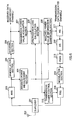
- FIG. 1 is a block diagram showing a schematic configuration of a base station apparatus according to one embodiment of the present invention
- FIG. 2 is a block diagram showing a schematic configuration of a mobile station apparatus according to one embodiment of the present invention.
- the base station apparatus shown in FIG. 1, and the mobile station apparatus shown in FIG. 2 are applied in a mobile communication system according to a TDD method.
- a transmission power control section 101 controls the transmission power of a broadcast channel signal to be at a predetermined transmission power value so that the broadcast channel signal may be broadcast over the whole cell which the above base station apparatus covers.
- a transmission power value information generation section 102 converts the transmission power value of the broadcast channel signal into information bit strings.
- a multiplexing section(MS) 103 multiplexes information indicating the transmission power value over a data part of the broadcast channel signal.
- An encoding section(ES) 104 performs predetermined encoding processing of the broadcast channel signal.
- a pilot signal multiplexing section (PSMS) 105 adds a pilot signal, which is used in the mobile station apparatus for acquisition of synchronization, channel estimation and so on, to the data part of the broadcast channel signal.
- PSMS pilot signal multiplexing section
- a modulation section 106 performs predetermined modulation processing of the broadcast channel signal.
- a transmission RF section(TRS) 107 amplifies the broadcast channel signal according to the control of the transmission power control section 101 for predetermined radio processing of the broadcast signal.
- a duplexer 108 switches transmitting and receiving of signals to be transmitted and received through an antenna 109.
- a receiving RF section(RRS) 110 performs predetermined radio processing of a dedicated channel signal transmitted from the mobile station apparatus.
- a demodulation section 111 performs predetermined demodulation processing of the dedicated channel signal.
- a decoding section 112 performs predetermined decoding processing of the dedicated channel signal. Thereby, received data are obtained.
- a propagation loss value acquisition section 113 acquires a propagation loss value, which is multiplexed on the received data, of a downlink.
- a channel assignment section 114 assigns a channel, substituting the above acquired propagation loss value of the downlink for that of the uplink.
- a duplexer 201 switches transmitting and receiving of signals to be transmitted and received through an antenna 202 in the mobile station apparatus shown in FIG. 2.
- a receiving RF section(RRS) 203 performs predetermined radio processing of the broadcast channel signal transmitted from the base station apparatus.
- a received power measurement section 204 measures the received power of the broadcast channel signal.
- a demodulation section 205 performs predetermined demodulation processing of the broadcast channel signal.
- a decoding section 206 performs predetermined decoding processing of the broadcast channel signal. Thereby, received data are obtained.
- a transmission power value acquisition section 207 acquires a transmission power value, which is multiplexed on the received data, of the broadcast channel signal.
- a propagation loss calculation section 208 calculates the propagation loss value, using the transmission power value and the received power value of the broadcast channel signal.
- a propagation loss value information generation section 209 converts the propagation loss value into information bit strings.
- a transmission power control section 210 controls the transmission power of the dedicated channel signal according to the propagation loss.
- a multiplexing section(MS) 211 multiplexes information indicating the propagation loss value over the data part of the dedicated channel signal.
- An encoding section(ES) 212 performs predetermined encoding processing of the dedicated channel signal.
- a pilot signal multiplexing section (PSMS) 213 adds a pilot signal, which is used in the base station apparatus for acquisition of synchronization, channel estimation and so on, to the data part of the dedicated channel signal.
- PSMS pilot signal multiplexing section
- a modulation section 214 performs predetermined modulation processing of the dedicated channel signal.
- a transmission RF section(TRS) 215 amplifies the dedicated channel signal according to the control by the transmission power control section 210 for predetermined radio processing of the dedicated channel signal.
- FIG. 3 is a view of a configuration of the broadcast channel signal and the dedicated channel signal
- FIG. 4 is a graph showing a change in the propagation loss.
- the broadcast channel signal are transmitted, using the downlink, in order to broadcast information for specification of the cell, in which a mobile station is located, to all mobile stations existing in the cell which the base station covers. And, the transmission power of the broadcast channel signal is controlled to be at a predetermined value so that the broadcast channel signal may be transmitted to the whole cell.
- a signal indicating the above predetermined transmission power value is generated first by the transmission power control section 101, and output to the transmission power value information generation section 102 and the transmission RF section(TRS) 107.
- the signal indicating the transmission power value of the broadcast channel signal is converted into information bit strings for output to the multiplexing section(MS) 103.
- the information indicating the transmission power value is multiplexed in the multiplexing section(MS) 103 over transmission data including information for specification of the cell, and so on. That is, the information indicating the transmission power value is multiplexed over the data part, shown in FIG. 3, of the broadcast channel signal, and transmitted to each mobile station.
- the predetermined encoding processing of the broadcast channel signal output from the multiplexing section(MS) 103 is performed in the encoding section(ES) 104, and predetermined modulation processing thereof is performed in the modulation section 106 after addition of pilot parts as shown in FIG. 3 in the pilot signal multiplexing section(PSMS) 105.
- the pilot signals are known signal both in the base station apparatus and the mobile station apparatus.
- the broadcast channel signal output from the modulation section 106 is transmitted to the mobile station apparatus through the duplexer 108 and the antenna 109 after amplification of the transmission power of the above signal to the above predetermined transmission power in the transmission RF section(TRS) 107.
- the cell, where the mobile station is currently located, and so on. are specified at power-on by reference to the broadcast channel signal after establishment of synchronization by a synchronous channel signal.
- the broadcast channel signal transmitted from the base station apparatus are received through the antenna 202 and the duplexer 201 in the mobile station apparatus shown in FIG. 2.
- Predetermined radio processing of the broadcast channel signal, which is received when there is generated a request for channel assignment, is performed in the receiving RF section(RRS) 203, and the above signal is output to the received power measurement section 204, and a demodulation section 205.
- Predetermined decoding processing of the broadcast channel signal output from the receiving RF section(RRS) 203 is performed in the decoding section 206 after predetermined demodulation processing in the demodulation section 205. Thereby, received data are obtained.
- the received power measurement section 204 the received power value of the pilot section in the broadcast channel signal is measured, and output to the propagation loss calculation section 208.
- the transmission power value acquisition section 207 the transmission power value, which is multiplexed in the base station apparatus over the data part of the broadcast channel signal, of the broadcast channel signal is fetched from the data part, and output to the propagation loss calculation section 208.
- the propagation loss value of the downlink is calculated, using the transmission power value output from the transmission power value acquisition section 207, and the received power value output from the received power measurement section 204. Specifically, for example, the propagation loss calculation section 208 calculates propagation loss value of the downlink by subtraction of the received power value output from the received power measurement section 204 from the transmission power value output from the transmission power value acquisition section 207.
- the longer distance between the base station and the mobile station causes the more reduced received power value of the broadcast channel signal as shown in FIG. 4, as the broadcast channel signal is transmitted from the base station to all mobile stations at predetermined power. Therefore, the propagation loss of the downlink at each mobile station is calculated in each mobile station, using the transmission power value and the received power value of the broadcast channel signal. In other words, the distance between the base station and the mobile station is calculated in each mobile station.
- the signal indicating the propagation loss value of the downlink is output to the propagation loss value information generation section 209 and the transmission power control section 210.
- the signal indicating the propagation loss value of the downlink are converted into information bit strings, and output to the multiplexing section(MS) 211.
- the information indicating the propagation loss value of the downlink is multiplexed over the transmission data in the multiplexing section(MS) 211. That is, the information indicating the propagation loss value of the downlink is multiplexed over the data part shown in FIG. 3 of the dedicated channel signal, and transmitted to the base station apparatus.
- Predetermined encoding processing of the dedicated channel signal output from the multiplexing section(MS) 211 is performed in the encoding section(ES) 212, and predetermined modulation processing of the dedicated channel signal is performed in the modulation section 214, after addition of the pilot part by the pilot signal multiplexing section(PSMS) 213 as shown in FIG. 3.
- a value after addition of the calculated propagation loss value to the desired received power value in the base station is calculated as a transmission power value of the dedicated channel signal.
- the dedicated channel signal output from the modulation section 214 is transmitted to the base station apparatus through the duplexer 201 and the antenna 202, after the above channel signal is amplified so that the transmission power value of the above channel signal becomes the one calculated in the transmission power control section 210 in the transmission RF section(TRS) 215. That is, transmission power control of the dedicated channel signal is performed in each mobile station so that all received power values become the same in the base station apparatus.
- predetermined radio processing of the dedicated channel signal received through the antenna 109 and the duplexer 108 is performed in the receiving RF section (RRS) 110, and predetermined decoding processing thereof is performed in the decoding section 112 after predetermined demodulation processing thereof at the demodulation section 111.
- received data are obtained.
- the base station assigning channels may not estimate propagation losses of the uplinks for each mobile station.
- the propagation loss value, which is multiplexed over the data part of the dedicated channel signal in the mobile station apparatus, of the downlink is fetched from the data part by the propagation loss value acquisition section 113 for output to the channel assignment section 114, when requests for channel assignment are caused at outgoing calls or incoming ones. Thereafter, the channel assignment is performed in the channel assignment section 114, substituting the propagation loss values of the downlinks for the propagation loss values of the uplinks.
- the channel assignment is performed as specifically described in the following.
- the mobile station apparatus is configured to obtain the propagation loss values of the downlinks, and to transmit the above values to the base station apparatus.
- the base station apparatus and the mobile station apparatus may be configured as shown in FIG. 5 and FIG. 6, in which the base station apparatus obtains the propagation loss values of the downlinks.
- FIG. 5 is a block diagram showing a schematic configuration of another base station apparatus according to one embodiment of the present invention
- FIG. 6 is a block diagram showing a schematic configuration of another mobile station apparatus according to one embodiment of the present invention.
- parts similar to those of the base station apparatus shown in FIG. 1 and to those of the mobile station apparatus shown in FIG. 2 are denoted by the same reference numerals as those in FIG. 1 and FIG. 2, and detailed description will be eliminated.
- a transmission power control section 501 controls the transmission power of a broadcast channel signal to be at a predetermined value of transmission power so that the broadcast channel signal may be broadcast over the whole cell which the base station apparatus covers . And, the transmission power control section 501 generates a signal indicating the above predetermined transmission power value for output to a propagation loss calculation section 503, a transmission power value information generation section 102, and a transmission RF section(TRS) 107.
- a received power value acquisition section 502 acquires the received power value, which is measured and multiplexed over the received data in the mobile station apparatus, of the broadcast channel signal.
- the propagation loss calculation section 503 calculates a propagation loss value, using the transmission power value and the received power value of the broadcast channel signal.
- a received power measurement section 601 measures the received power of the broadcast channel signal, and outputs a signal indicating the received power value to a received power value information generation section 602 and a propagation loss calculation section 208, in the mobile station apparatus shown in FIG. 6.
- the received power value information generation section 602 converts the received power value, which is measured in the received power measurement section 601, of the broadcast channel signal into information bit strings.
- the base station apparatus and the mobile station apparatus which have the above configuration, will be described.
- the received power measurement section 601 of the mobile station apparatus shown in FIG. 6 the received power value of the pilot section in the broadcast channel signal is measured, and output to the received power value information generation section 602.
- the signal indicating the received power value of the broadcast channel signal is converted into an information bit string, and output to a multiplexing section(MS) 211.
- the information indicating the received power value of the broadcast channel signal is multiplexed over the transmission data in the multiplexing section(MS) 211. That is, the information indicating the received power value of the broadcast channel signal is multiplexed over the data part shown in FIG. 3 of the dedicated channel signal and transmitted to the base station apparatus.
- the received power value of the broadcast channel signal which is multiplexed over the data part of the dedicated channel signal, is fetched in the received power value acquisition section 502, and output to the propagation loss calculation section 503, in the base station apparatus shown in FIG. 5.
- the signal indicating the predetermined transmission power value of the broadcast channel signal is output from the transmission power control section 501 to the propagation loss calculation section 503.
- the propagation loss value of the downlink is calculated, using the transmission power value output from the transmission power control section 501 and the received power value output from the received power value acquisition section 502. Specifically, for example, the propagation loss calculation section 503 calculates propagation loss values of the downlink by subtraction of the received power value output from the received power value acquisition section 502 from the transmission power value output from the transmission power control section 501.
- the signal indicating the propagation loss value of the downlink is output to a channel assignment section 114.
- channel assignment is performed in the channel assignment section 114, substituting the propagation loss value of the downlink for that of the uplink.
- the channel assignment section 114 performs the channel assignment, using the propagation loss value as it is.
- the channel assignment section 114 may assign channels by using a value, which is obtained based on the propagation loss value and indicates the communication channel quality (for example, desired signal to interference signal power ratio and so on), as described in the following. That is,
- the ARP method has been used as a channel assignment method in the above description, but there is no limitation to the above assignment method, and any methods, which perform the channel assignment based on the value indicating the propagation loss value, or the communication channel quality, may be used as the above assignment method.
- broadcast channel signals have been used for control channel signals, which are transmitted at a predetermined power, on downlinks in the above description, but there is no limitation to the above control channel signals, and any control channel signals, which are transmitted at a predetermined power on the downlinks, may be used as the above control channel signals.
- pilot signals are added to data signals, but there is no limitation to the above configuration, and a configuration, in which the pilot signals are transmitted through another channel different from the one for the data signals, may be used.
- the channel assignment is performed substituting the propagation loss of the downlinks obtained from the transmitting power and received power of control channel signals transmitted at a predetermined power from the base station to each mobile station for the propagation loss of the uplinks.
- reuse partitioning by which the best cell reuse factor is set for each channel, based on the size of the propagation losses, in a mobile communication system, in which the transmission power control is performed on the uplinks, according to the TDD method.
Landscapes
- Engineering & Computer Science (AREA)
- Signal Processing (AREA)
- Quality & Reliability (AREA)
- Computer Networks & Wireless Communication (AREA)
- Mobile Radio Communication Systems (AREA)
- Time-Division Multiplex Systems (AREA)
Abstract
Description
Claims (8)
- A mobile station apparatus used in a mobile communication system according to a TDD method, comprising:a measurer for measuring a received power value of a control channel signal transmitted from a base station apparatus at predetermined power;a calculator for calculating a propagation loss value of a downlink, using a transmission power value and the received power value of the control channel signal; anda transmitter for transmitting the propagation loss value to the base station apparatus.
- The mobile station apparatus according to claim 1, wherein
said measurer measures a received power value of a known signal included in the control channel signal at outgoing calls or incoming ones. - A base station apparatus used in a mobile communication system according to a TDD method, comprising:an acquirer for acquiring the propagation loss value of the downlink transmitted from said mobile station apparatus according to claim 1; anda channel assignor for assigning a radio communication channel based on the propagation loss value.
- A mobile station apparatus used in a mobile communication system according to a TDD method, comprising:a measurer for measuring a received power value of a control channel signal transmitted from a base station apparatus at predetermined power; anda transmitter for transmitting said the received power value to said base station apparatus.
- The mobile station apparatus according to claim 4, wherein
said measurer measures a received power value of a known signal included in the control channel signal at outgoing calls or incoming ones. - A base station apparatus used in a mobile communication system according to a TDD method, comprising:an acquirer for acquiring the received power value transmitted from said mobile station apparatus according to claim 4;a calculator for calculating a propagation loss value of a downlink, using a transmission power value and the received power value of the control channel signal; anda channel assignor for assigning a radio communication channel based on the propagation loss value.
- A radio communication channel assignment method in a mobile communication system according to a TDD method, whereina mobile station apparatus calculates a propagation loss value of a downlink, and transmits the propagation loss value to a base station apparatus; andthe base station apparatus assigns a radio communication channel based on the propagation loss value of the downlink.
- A radio communication channel assignment method in a mobile communication system according to a TDD method, whereina mobile station apparatus measures a received power value of a control channel signal, and transmits the received power value to a base station apparatus; andthe base station apparatus calculates a propagation loss value of a downlink using a transmission power value and the received power value of the control channel signal, and assigns a radio communication channel based on the propagation loss value.
Applications Claiming Priority (3)
| Application Number | Priority Date | Filing Date | Title |
|---|---|---|---|
| JP2000049848A JP2001238252A (en) | 2000-02-25 | 2000-02-25 | Mobile station device, base station device, and wireless communication channel assignment method |
| JP2000049848 | 2000-02-25 | ||
| PCT/JP2001/001290 WO2001063958A1 (en) | 2000-02-25 | 2001-02-22 | Mobile station apparatus, base station apparatus, and method for allotting radio communication channels |
Publications (2)
| Publication Number | Publication Date |
|---|---|
| EP1175120A1 true EP1175120A1 (en) | 2002-01-23 |
| EP1175120A4 EP1175120A4 (en) | 2002-08-28 |
Family
ID=18571718
Family Applications (1)
| Application Number | Title | Priority Date | Filing Date |
|---|---|---|---|
| EP01906201A Withdrawn EP1175120A4 (en) | 2000-02-25 | 2001-02-22 | MOBILE STATION APPARATUS, BASE STATION APPARATUS, AND COMMUNICATION CHANNEL ASSIGNMENT METHOD |
Country Status (7)
| Country | Link |
|---|---|
| US (1) | US20020160798A1 (en) |
| EP (1) | EP1175120A4 (en) |
| JP (1) | JP2001238252A (en) |
| KR (1) | KR20010113892A (en) |
| CN (1) | CN1363196A (en) |
| AU (1) | AU3412001A (en) |
| WO (1) | WO2001063958A1 (en) |
Cited By (2)
| Publication number | Priority date | Publication date | Assignee | Title |
|---|---|---|---|---|
| CN104410959A (en) * | 2008-06-25 | 2015-03-11 | 苹果公司 | Feedback information comprising individual subband related to wireless channel |
| EP2221988B1 (en) * | 2005-08-22 | 2016-06-22 | Sony Corporation | Uplink resource allocation to control intercell interference in a wireless communication system |
Families Citing this family (22)
| Publication number | Priority date | Publication date | Assignee | Title |
|---|---|---|---|---|
| GB0126267D0 (en) * | 2001-11-01 | 2002-01-02 | Nokia Corp | Repeater detection |
| JP4184969B2 (en) * | 2001-11-17 | 2008-11-19 | サムスン エレクトロニクス カンパニー リミテッド | Signal measuring apparatus and method for handover in a mobile communication system |
| TWI493914B (en) * | 2002-05-13 | 2015-07-21 | Interdigital Tech Corp | Allocating resources to users in a slotted coded multiple access system using beams |
| JP3574443B2 (en) * | 2002-08-20 | 2004-10-06 | 松下電器産業株式会社 | Communication terminal device, base station device, and transmission power control method |
| WO2004073337A1 (en) * | 2003-02-12 | 2004-08-26 | Research In Motion Limited | Apparatus, and associated, method, for facilitating initiation of channel allocation to communicate data in a radio communication system. |
| KR100617729B1 (en) * | 2004-03-05 | 2006-08-28 | 삼성전자주식회사 | Frequency Resource Allocation System based on Multi-frequency Reuse Rate in Cellular Communication Systems |
| JP2006020043A (en) * | 2004-07-01 | 2006-01-19 | Nec Corp | Service area deciding method |
| BRPI0513954A (en) * | 2004-07-30 | 2008-05-20 | Matsushita Electric Industrial Co Ltd | Wireless transmitter and wireless transmission method |
| JP4834352B2 (en) * | 2005-06-14 | 2011-12-14 | 株式会社エヌ・ティ・ティ・ドコモ | Base station, mobile station, and power control method |
| JP4836536B2 (en) * | 2005-09-30 | 2011-12-14 | セイコープレシジョン株式会社 | Existence range identification system, existence range identification method, and program |
| US7620367B2 (en) * | 2005-10-31 | 2009-11-17 | Ipwireless, Inc. | Frequency domain unscheduled transmission in a TDD wireless communications system |
| EP2063655A4 (en) * | 2006-09-20 | 2014-06-04 | Nec Corp | CARRIER ALLOCATION METHOD FOR CELLULAR SYSTEM, CELLULAR SYSTEM, BASE STATION, AND MOBILE STATION |
| US8020075B2 (en) | 2007-03-16 | 2011-09-13 | Apple Inc. | Channel quality index feedback reduction for broadband systems |
| US8711786B2 (en) | 2008-05-13 | 2014-04-29 | Qualcomm Incorporated | Autonomous downlink code selection for femto cells |
| US8725083B2 (en) | 2008-05-13 | 2014-05-13 | Qualcomm Incorporated | Self calibration of downlink transmit power |
| US8737317B2 (en) | 2008-05-13 | 2014-05-27 | Qualcomm Incorporated | Autonomous carrier selection for femtocells |
| US8718696B2 (en) * | 2008-05-13 | 2014-05-06 | Qualcomm Incorporated | Transmit power selection for user equipment communicating with femto cells |
| US8781462B2 (en) * | 2009-09-28 | 2014-07-15 | Itron, Inc. | Methodology and apparatus for validating network coverage |
| US8879475B2 (en) | 2012-05-15 | 2014-11-04 | Apple Inc. | Adaptive channel state feedback in discontinuous reception scenarios based on connection characteristics |
| US8989743B2 (en) | 2012-08-28 | 2015-03-24 | Apple Inc. | Battery conservation in stationary conditions for a wireless device |
| CN107231680B (en) * | 2016-03-23 | 2021-04-30 | 中兴通讯股份有限公司 | Method and device for open-loop power control |
| JP6708052B2 (en) * | 2016-08-18 | 2020-06-10 | 富士電機株式会社 | Wireless communication network system, wireless communication network system construction method, and wireless terminal |
Family Cites Families (10)
| Publication number | Priority date | Publication date | Assignee | Title |
|---|---|---|---|---|
| US5287544A (en) * | 1991-10-17 | 1994-02-15 | Motorola, Inc. | Method of channel assignment by matching channel interference with channel link loss |
| JP3220735B2 (en) * | 1994-03-04 | 2001-10-22 | 日本電信電話株式会社 | Radio base station transmission power control apparatus and control method |
| US5491837A (en) * | 1994-03-07 | 1996-02-13 | Ericsson Inc. | Method and system for channel allocation using power control and mobile-assisted handover measurements |
| US5603093A (en) * | 1994-12-28 | 1997-02-11 | Ntt Mobile Communications Network, Inc. | Method for monitoring the state of interference by a base station of a mobile radio communication system |
| JP2762965B2 (en) * | 1995-09-04 | 1998-06-11 | 日本電気株式会社 | Base station transmission power control method |
| JP3375465B2 (en) * | 1995-09-25 | 2003-02-10 | 松下電器産業株式会社 | Transmission output control device |
| US6108321A (en) * | 1996-06-28 | 2000-08-22 | Lucent Technologies Inc. | Interference based dynamic channel assignment |
| US5886988A (en) * | 1996-10-23 | 1999-03-23 | Arraycomm, Inc. | Channel assignment and call admission control for spatial division multiple access communication systems |
| JP3107048B2 (en) * | 1998-06-09 | 2000-11-06 | 日本電気株式会社 | CDMA communication system and frequency allocation method in CDMA communication system |
| JP3204310B2 (en) * | 1998-08-12 | 2001-09-04 | 日本電気株式会社 | CDMA mobile communication system and downlink transmission power control method thereof |
-
2000
- 2000-02-25 JP JP2000049848A patent/JP2001238252A/en active Pending
-
2001
- 2001-02-22 KR KR1020017013612A patent/KR20010113892A/en not_active Ceased
- 2001-02-22 AU AU34120/01A patent/AU3412001A/en not_active Abandoned
- 2001-02-22 CN CN01800300A patent/CN1363196A/en active Pending
- 2001-02-22 WO PCT/JP2001/001290 patent/WO2001063958A1/en not_active Ceased
- 2001-02-22 EP EP01906201A patent/EP1175120A4/en not_active Withdrawn
- 2001-02-22 US US09/959,313 patent/US20020160798A1/en not_active Abandoned
Cited By (6)
| Publication number | Priority date | Publication date | Assignee | Title |
|---|---|---|---|---|
| EP2221988B1 (en) * | 2005-08-22 | 2016-06-22 | Sony Corporation | Uplink resource allocation to control intercell interference in a wireless communication system |
| EP2221985B1 (en) * | 2005-08-22 | 2016-06-29 | Sony Corporation | Uplink resource allocation to control intercell interference in a wireless communication system |
| EP2197124B1 (en) * | 2005-08-22 | 2016-08-31 | Sony Corporation | Uplink resource allocation to control intercell interference in a wireless communication system |
| CN104410959A (en) * | 2008-06-25 | 2015-03-11 | 苹果公司 | Feedback information comprising individual subband related to wireless channel |
| CN104410959B (en) * | 2008-06-25 | 2017-12-08 | 苹果公司 | Include the feedback information of the independent subband on wireless channel |
| US10097247B2 (en) | 2008-06-25 | 2018-10-09 | Apple Inc. | Including feedback information regarding an individual subband of a wireless channel |
Also Published As
| Publication number | Publication date |
|---|---|
| JP2001238252A (en) | 2001-08-31 |
| AU3412001A (en) | 2001-09-03 |
| KR20010113892A (en) | 2001-12-28 |
| EP1175120A4 (en) | 2002-08-28 |
| US20020160798A1 (en) | 2002-10-31 |
| CN1363196A (en) | 2002-08-07 |
| WO2001063958A1 (en) | 2001-08-30 |
Similar Documents
| Publication | Publication Date | Title |
|---|---|---|
| EP1175120A1 (en) | Mobile station apparatus, base station apparatus, and method for allotting radio communication channels | |
| US6483816B2 (en) | CDMA communication system and its transmission power control method | |
| KR100866334B1 (en) | Apparatus and method for supporting multiple links in a multihop relay cellular network | |
| KR101517241B1 (en) | Method of selecting relay station | |
| EP2590441A1 (en) | System and method for one cell to cover multiple areas | |
| EP1459461B1 (en) | Utra tdd time slots allocation | |
| KR20020026277A (en) | Base station apparatus and handover control method | |
| KR20000017641A (en) | Extended range concentric cell base station | |
| KR101789559B1 (en) | Apparatus and method to transmit/receive a signal in a mobile communication system including a plurality of radio units | |
| EP0986192A2 (en) | Mobile station communication apparatus, base station communication apparatus and radio communication method for transmission power control | |
| KR101465245B1 (en) | Signal processing system, digital signal processing apparatus and method for controlling transmitting power in the same | |
| JPH11275035A (en) | Mobile station communication device, base station communication device, and wireless communication system | |
| US10530502B2 (en) | Communication devices, control device and methods thereof | |
| US7149204B2 (en) | Base station device and channel assigning method | |
| AU722795B2 (en) | Method of improving connection quality and system capacity, and a cellular radio system | |
| US6539234B1 (en) | Radio communication terminal and transmission power control method | |
| JP2002325281A (en) | Communication control method | |
| US20030130011A1 (en) | Base station apparatus and channel assigning method | |
| EP1185124A1 (en) | Mobile station apparatus and radio communication method | |
| KR100959333B1 (en) | Bidirectional communication device using auxiliary band in wireless communication system | |
| KR20030055649A (en) | A dynamic grouping trasmitter/receiver and control system of remote antenna units and the dynamic grouping method in cdma bunched system | |
| KR100531359B1 (en) | The Timing Alignment Bit transmission method for uplink synchronous transmission scheme systems of ansynchronous scheme | |
| JPH11163779A (en) | Radio equipment | |
| KR20150008317A (en) | Method for changing configuration of cells for joint transmission on servicing carrier aggregation, mobile communication system for performing the same and digital signal processing apparatus | |
| KR20060073597A (en) | Operation method and wireless station for wireless communication system |
Legal Events
| Date | Code | Title | Description |
|---|---|---|---|
| PUAI | Public reference made under article 153(3) epc to a published international application that has entered the european phase |
Free format text: ORIGINAL CODE: 0009012 |
|
| 17P | Request for examination filed |
Effective date: 20011122 |
|
| AK | Designated contracting states |
Kind code of ref document: A1 Designated state(s): AT BE CH CY DE DK ES FI FR GB GR IE IT LI LU MC NL PT SE TR |
|
| AX | Request for extension of the european patent |
Free format text: AL;LT;LV;MK;RO;SI |
|
| A4 | Supplementary search report drawn up and despatched |
Effective date: 20020716 |
|
| AK | Designated contracting states |
Kind code of ref document: A4 Designated state(s): AT BE CH CY DE DK ES FI FR GB GR IE IT LI LU MC NL PT SE TR |
|
| 17Q | First examination report despatched |
Effective date: 20020924 |
|
| STAA | Information on the status of an ep patent application or granted ep patent |
Free format text: STATUS: THE APPLICATION IS DEEMED TO BE WITHDRAWN |
|
| 18D | Application deemed to be withdrawn |
Effective date: 20030709 |
|
| RBV | Designated contracting states (corrected) |
Designated state(s): DE FR GB |