EP1175041A2 - Configuration control of a computer network - Google Patents
Configuration control of a computer network Download PDFInfo
- Publication number
- EP1175041A2 EP1175041A2 EP01000253A EP01000253A EP1175041A2 EP 1175041 A2 EP1175041 A2 EP 1175041A2 EP 01000253 A EP01000253 A EP 01000253A EP 01000253 A EP01000253 A EP 01000253A EP 1175041 A2 EP1175041 A2 EP 1175041A2
- Authority
- EP
- European Patent Office
- Prior art keywords
- initiator
- port
- state
- initiators
- computer network
- Prior art date
- Legal status (The legal status is an assumption and is not a legal conclusion. Google has not performed a legal analysis and makes no representation as to the accuracy of the status listed.)
- Withdrawn
Links
- 239000003999 initiator Substances 0.000 claims abstract description 205
- 238000000034 method Methods 0.000 claims abstract description 80
- 230000002401 inhibitory effect Effects 0.000 claims abstract description 9
- 238000004590 computer program Methods 0.000 claims 1
- 230000004044 response Effects 0.000 description 5
- 238000011084 recovery Methods 0.000 description 4
- 230000002250 progressing effect Effects 0.000 description 1
- 238000000638 solvent extraction Methods 0.000 description 1
- 230000007704 transition Effects 0.000 description 1
Images


Classifications
-
- H—ELECTRICITY
- H04—ELECTRIC COMMUNICATION TECHNIQUE
- H04L—TRANSMISSION OF DIGITAL INFORMATION, e.g. TELEGRAPHIC COMMUNICATION
- H04L41/00—Arrangements for maintenance, administration or management of data switching networks, e.g. of packet switching networks
- H04L41/08—Configuration management of networks or network elements
- H04L41/0866—Checking the configuration
-
- H—ELECTRICITY
- H04—ELECTRIC COMMUNICATION TECHNIQUE
- H04L—TRANSMISSION OF DIGITAL INFORMATION, e.g. TELEGRAPHIC COMMUNICATION
- H04L41/00—Arrangements for maintenance, administration or management of data switching networks, e.g. of packet switching networks
- H04L41/08—Configuration management of networks or network elements
Definitions
- the present invention relates to computer networks and, more particularly, to a method and system for configuring a computer network that includes devices with configurable full duplex bi-directional ports.
- a computer network organized as a serial storage architecture is a collection of nodes interconnected by a full duplex bi-directional serial connection.
- a standard for SSA is set forth by the American National Standards Institute (ANSI) Task Group X3T10.1 in documents SSA-S2P, SSA-TL1 and SSA-PH1. Additional references are available from the SSA Industry Association in documents SSA-IA/95PH and SSA-IA95SP.
- SSA data is transferred between the nodes in data packets using a store and forward technique sometimes referred to as a bucket brigade.
- each node is coupled to two other nodes and data can travel throughout the network in a full circle.
- the nodes can be connected in a string, that is, in a line, that terminates without being connected to a subsequent node.
- data communication throughout the network proceeds bi-directionally.
- Each node has two ports, namely P1 and P2, and each port has an input and an output.
- Each port is further characterized by a state that can be defined as "on-line", “wrapped” or "off-line". In the on-line state the port is able to bi-directionally communicate with a next port located on an adjacent node. In the wrapped state, the port is coupled to itself by having its output coupled to its input. In the off-line state, the port is not able to communicate with another port, and it is not wrapped.
- An SSA network is often referred to as a web.
- One web can be partitioned into several smaller webs, or separate webs can be combined to form one larger web.
- Each web will have at least one initiator, which is a processor for routing data and commands to the nodes in the web.
- the initiators are ranked from a highest priority to a lowest priority. Based on this priority, the initiators will collectively designate one of the initiators as a master initiator.
- a master initiator is responsible for handling error conditions that are reported to it by devices on its web.
- the master initiator is also responsible for setting the state of the ports on its web.
- An initiator acquires a view of the topology of the network through a process known as "walking the web.”
- the initiator examines the ports of the devices in the web of which the initiator is a member, and stores the state of the ports in a topology table.
- the topology table describes the interconnection between nodes, i.e., the manner in which ports are linked together. It typically includes information such as a node identifier, and the state of each port at the node.
- Each initiator maintains its own topology table.
- a configuration table includes the same information as a topology table, and further includes initiator registration information and port error handling parameters.
- a device on a web encounters a fault, the device generates an error message, known as an "Async Alert" in SSA parlance. If the Async Alert indicates a port communications problem, the master initiator of the web responds by performing an automatic error recovery process in which it walks the web to examine and possibly request a change of the state of the ports on the web. The master initiator may also issue a message known as a "Master Alert" to the non-master initiators. In response to a Master Alert, a non-master will walk the web and examine the ports on the web. However, a non-master initiator does not request a change of the state of a port.
- a master initiator can issue a request for a given port to assume the wrapped state. Provided that the given port is operating normally, the given port will respond by wrapping itself.
- a master initiator can issue a request for a given port to assume the on-line state. If the given port can establish communication with an adjacent port, then the given port assumes the on-line state. If the given port cannot establish communication with the adjacent port, then the given port assumes the off-line state. This failure to establish communication can occur when (a) there is no adjacent port, such as when the given port is at the end of a string, (b) the adjacent port is in the wrapped state, or (c) the communication link between the given port and the adjacent port has a problem. Note that the port may automatically transition from the on-line state to the off-line state depending on its ability to establish communication with the adjacent port.
- initiator mastership can change, and a new master initiator will be responsible for the state of the ports.
- a first initiator cannot read a topology table from second initiator. Consequently, in a case where the first initiator becomes a master for a web of which the first initiator has no knowledge, the first initiator has no opportunity to preserve the state of a port located in that web.
- the present invention is directed toward a method and system for configuring a computer network that includes full duplex bi-directional ports and one or more processors having an ability to examine and request that each port assume a particular state.
- the processor also known as an initiator, maintains a copy of a port information map (PIM) that contains data describing a desired state of all the ports in the network.
- PIM port information map
- a control unit imposes a desired configuration by (a) inhibiting all initiators from issuing requests for the ports to change state, (b) sending the PIM describing the desired configuration to the initiators, and (c) enabling the initiators to issue requests for the ports to assume states in accordance with the PIM.
- the present invention defines and imposes a desired configuration for the entire computer network and synchronizes the configuration among multiple initiators.
- the invention provides for the cases of partitioning the network into smaller networks, and for joining networks together. Because the invention affirmatively defines the state of all ports, when a master initiator walks the web, an isolated node remains isolated.
- the present invention is effective to impose the desired configuration in a case where the network includes multiple webs and multiple initiators and also to maintain the desired configuration in a case where the topology of the network changes.
- the present invention provides a method for configuring a computer network that includes devices with full duplex bi-directional ports and an initiator having an ability to examine and request each port to assume a particular state in accordance with data describing a desired configuration.
- Each port can assume an on-line, off-line or wrapped state.
- a control unit constructs a port information map (PIM) that defines a desired state for each port in the entire computer network.
- the control unit issues the PIM to the initiator.
- the initiator configures the web, it requests the ports to assume desired states in accordance with the PIM.
- the PIM provides all initiators with the desired state of all ports in the network. Therefore a given initiator has knowledge of the desired state of all ports, including those that are not in the same web as the given initiator. This allows an initiator to manage the ports in a case where the network topology changes.
- Fig. 1 is a schematic representation of a computer network 1 organized in a serial storage architecture loop topology.
- the principal components of the network are a host processor 5 with a user interface 3, a control unit 10, initiators 15 - 17, and a series of nodes occupied by disk drives 50 - 67.
- any type of device that can be connected to a computer network including typical input/output devices can occupy the nodes.
- User interface 3 enables a user to send commands and data to, and receive data from, computer network 1.
- Host processor 5 communicates with control unit 10 over a bus 6, and control unit 10 communicates with initiators 15 - 17 via a bus 12.
- Initiators 15 - 17 and disk drives 50 - 67 are connected to a network comprising three segments 20, 21 and 22.
- Each of the initiators 15 - 17 and disk drives 50 -67 include two full duplex bi-directional ports, i.e. P1 and P2, through which data is exchanged.
- a device need not be limited to two ports, and the present invention can be applied where the devices have any number of ports.
- Host processor 5 executes programs using data that is stored on disk drives 50 - 67.
- disk drive 50 for example, host processor 5 issues a command to control unit 10.
- control unit 10 issues a corresponding command to initiator 15, which passes the command to disk drive 50.
- the commands from the initiators 15 - 17 to the disk drives 50 - 67 provide for reading data from, and writing data to, disk drives 50 - 67, and for setting the state of ports on each of disk drives 50 - 67.
- Control unit 10 includes a processor 10a and memory 10b that can be loaded with a program or data from a storage media, such as data memory 8.
- a storage media such as data memory 8.
- control unit 10 issues a command to any initiator 15 - 17, the initiator acknowledges the command by returning a status packet indicating whether the initiator successfully completed the command.
- control unit 10 and initiators 15 - 17 are shown here as separate components, they may be integrated into a single housing, or even a single printed circuit board.
- One of the initiators 15 - 17 must be designated as a master initiator. This designation of mastership occurs during the web walking process.
- Each of the initiators 15 -17 has an identifier that also prioritizes the initiators. When a first initiator walks the web and encounters a second initiator, the first initiator reads the identifier of the second initiator. If the identifier of the first initiator indicates a higher priority, then the first initiator assumes mastership. If the identifier of the second initiator indicates a higher priority, then the first initiator concedes mastership. For the description that follows, assume that the initiators are prioritized as 15, 16 and 17, with initiator 15 having the highest priority.
- Computer network 1 can be organized into segments of smaller webs. For example, assume that devices 53 and 65 are isolated from the network. This would yield (a) a first web, configured as a string that included initiators 15 and 16, and devices 50 - 52 and 56 - 64, and (b) a second web, configured as a string that included initiator 17, and devices 54, 55, 66 and 67. Initiator 15 would assume mastership of the first web, and initiator 17 would assume mastership of the second web.
- a sample Port Information Map is set forth in Table 1, below. Referring again to Fig. 1, assume devices 53 and 65 are isolated. Note that in Table 1, device 53-P1 and -P2 are both indicated as “(undefined)”, device 52-P1 is “wrapped”, and device 54-P2 is “wrapped”. Also, device 65-P1 and -P2 are both indicated as “(undefined)”, device 64-P2 is “wrapped”, and device 66-P1 is "wrapped”.
- control unit 10 issues commands to the initiators 15 - 17.
- the commands include a Freeze Command, Query Configuration Command, Execute Port Information Map (XPIM) Command, Unfreeze Command, and Validate Configuration Command.
- XPIM Execute Port Information Map
- the Freeze Command inhibits all initiators from responding to an Async Alert by performing an automatic error recovery process. That is, the initiators are inhibited from issuing requests to change the states of the ports when responding to the Async Alert. Note that during regular operation, an initiator may respond to the Async Alert by performing an automatic error recovery process that alters the state of one or more ports.
- the Query Configuration Command causes an initiator to send data from its Configuration Table to the control unit. After obtaining a Configuration Table from each of the initiators in the network, the control unit can consider the current actual configuration, and develop a desired configuration, for the entire network.
- the control unit When issuing the Execute Port Information Map (XPIM) Command, the control unit also sends the PIM to an initiator.
- the XPIM causes the initiator to walk the web. If the initiator is a master initiator, it is thus enabled to issue requests for the ports in its web to assume states in accordance with the PIM.
- the Unfreeze Command enables the initiators to respond to an Async Alert by performing an automatic error recovery process. That is, the initiators are not inhibited from issuing requests to change the states of ports when responding to the Async Alert.
- the Validate Configuration Command causes an initiator to walk the web and to compare the actual port settings to data in the PIM.
- the initiator reports the result of this comparison to the control unit.
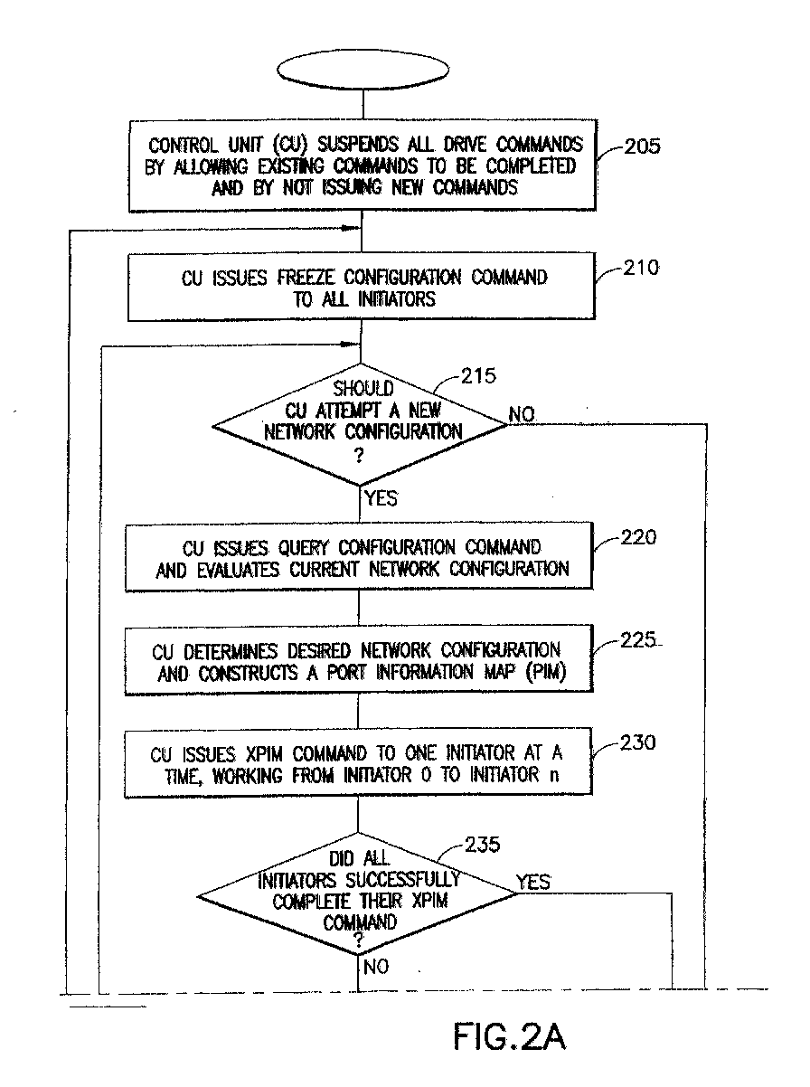
- Fig. 2 is a flowchart of a method for imposing a desired configuration on a computer network in accordance with the present invention. This method is applicable to a network having a single initiator, as well as a network having multiple webs and multiple initiators.
- step 205 the control unit (CU) suspends all drive commands by allowing existing drive commands to be completed, and by not issuing new commands. More particularly, the control unit waits for each initiator to acknowledge completion of all commands previously issued by the control unit. The method then advances to step 210.
- step 210 the control unit issues a Freeze Configuration Command to all initiators. All initiators are inhibited from issuing requests to change the states of the ports when responding to an Async Alert. This step ensures that the occurrence of an Async Alert does not interfere with the present process. The method then advances to step 215.
- step 215 the control unit determines whether to attempt to establish a new network configuration. This determination allows for a case where, after a predetermined number of attempts, the control unit has not been able to successfully establish communication with all of the initiators. If the control unit determines that it will not attempt to establish a new network configuration, then the method branches to step 275 and terminates. If the control unit determines that it will attempt to establish a new network configuration, then the method advances to step 220.
- step 220 the control unit issues a Query Configuration Command to each initiator.
- Query Configuration Command an initiator sends data from its Configuration Table to the control unit. The method then advances to step 225.
- step 225 the control unit establishes a desired configuration for the network, based on the actual configuration reported by each of the initiators in step 220.
- the control unit constructs a Port Information Map (PIM) describing the desired configuration for the entire network.
- PIM includes a desired setting for all ports in the network. The method then advances to step 230.
- a user of computer network 1 can define a desired configuration via user interface 3. Accordingly, the PIM would be based on input from the user.
- step 230 the control unit issues an Execute Port Information Map (XPIM) Command to each of the initiators in the network.
- the control unit sends the command to each initiator in a determined sequence. The sequence starts with the highest-ranking initiator (rank 0) and progresses in order of priority to the lowest-ranking initiator (rank n).
- the control unit With each XPIM Command the control unit also sends the PIM to the initiator describing a desired state of the ports.
- the initiator walks the web and constructs a topology table and a configuration table. If the initiator is a master initiator, it may also issue requests for the port states to be set in accordance with the PIM.
- the XPIM process as executed by an initiator is illustrated in Fig. 3 and described below in greater detail. The method then advances to step 235.
- a network By affirmatively defining a desired state for each port in the network, a network can be partitioned into smaller webs, or similarly, webs can be merged into a larger network. Stated more generally, the method can be applied where a network has M number of webs, each of the M number of webs including a respective initiator and a respective full duplex bi-directional port. After the initiators issue the requests for setting the ports to the desired states, the computer network can have N number of webs, where N is not equal to M.
- step 235 the control unit determines whether all initiators successfully executed the XPIM Commands that were issued in step 230. An initiator acknowledges a command from the control unit by returning a status packet indicating whether the initiator successfully completed the command. If all initiators successfully executed their respective XPIM Command, then the method advances to step 250. If all initiators did not successfully executed their respective XPIM Command, then the method advances to step 240.
- step 240 the control unit issues another XPIM Command to each of the initiators. As before, this is done in sequence starting with the highest-ranking initiator and progressing in order of priority to the lowest-ranking initiator. Each respective initiator executes the process illustrated in Fig. 3. The method then advances to step 245.
- step 245 the control unit determines whether all initiators successfully executed the XPIM Commands that were issued in step 240. If all initiators successfully executed their respective XPIM Command, then the method advances to step 250. If all initiators did not successfully executed their respective XPIM Command, then the method loops back to step 215.
- step 250 the control unit issues an Unfreeze Command to all initiators.
- the master initiators are thus permitted to request changes in the state of the ports when responding to Async Alerts.
- the method then advances to step 255.
- step 255 the control unit issues a Validate Configuration Command to each of the initiators.
- each initiator compares the actual configuration to data in the PIM.
- the initiators report the result of these comparisons to the control unit. The method then advances to step 260.
- step 260 the control unit determines whether the current configuration of the network conforms to the desired configuration of the network. More particularly, the control unit evaluates the reports sent by the initiators in step 255. If the reports from all initiators indicate that the current configuration matches the PIM, then the method advances to step 265. If the reports from all initiators do not indicate that the current configuration matches the PIM, then the method loops back to step 210.
- step 265 the control unit resumes regular operation by issuing disk drive commands to the initiators. The method then advances to step 270.
- step 270 the method terminates with a successful reconfiguration of the network.
- step 275 the method terminates with a failure.
- the control unit did not successfully establish the desired network configuration.
- Fig. 3 is a flowchart a method executed by an initiator, in response to receiving the Execute Port Information Map (XPIM) command from the control unit. The method begins with step 310.
- XPIM Execute Port Information Map
- step 310 the initiator walks the web and constructs a topology table. This process is illustrated in Fig. 4, and described below in greater detail. The method then advances to step 315.
- step 315 the method considers whether the initiator is a master initiator. This is accomplished by examining the current topology table that was constructed in step 310. If the initiator is a master, then the method advances to step 320. If the initiator is not a master, then the method branches to step 335.
- step 320 the initiator issues a request for each port in the initiator's web to assume the on-line state. This step ensures that the initiator can communicate with all ports in its web. That is, the initiator can affirmatively access ports that might otherwise be inaccessible because of a previously wrapped port at an intermediate node. The method then advances to step 325.
- step 325 for each port in the initiator's web, the initiator issues a request for the port to assume a desired state in accordance with data in the PIM. The method then advances to step 330.
- step 330 the initiator walks the web and constructs a topology table as shown in Fig. 4. The method then advances to step 335.
- step 335 the initiator constructs a configuration table.
- the configuration table is first built on the information contained in the topology table.
- the initiator adds information important to the operation and error handling of the network. This added information includes:
- step 340 The method then advances to step 340.
- step 340 the method considers whether the initiator is a master initiator. This is accomplished by examining the most current topology table constructed in steps 310 or 330. Note that a previous master initiator may have lost web mastership as a result of steps 320 and 325. If the initiator is a master, then the method advances to step 345. If the initiator is not a master, then the method branches to step 350.
- step 345 for each port in the initiator's web the initiator issues a request for the port to assume a final state in accordance with the configuration table.
- the port's final state includes mot only a setting in accordance with data in the PIM, but also settings important to the operation and error handling of the network. The method then advances to step 350.
- step 350 the initiator compares the actual configuration of the web, as represented in the initiator's configuration table, to the PIM. If the configurations match, then the method advances to step 355. If the configurations do not match, then the method advances to step 360.
- step 355 the XPIM is declared as a success.
- the method then advances to step 365.
- step 360 the XPIM is declared unsuccessful. The method then advances to step 365.
- step 365 the XPIM method ends.
- Fig. 4 is a flowchart of a method for an initiator to walk the web and construct a topology table. Initially, the topology table is empty. The method begins with step 410.
- step 410 the method considers whether the initiator has explored all nodes in the web in which the initiator is located. All nodes are explored when (a) the initiator encounters a given node for a second time, thus indicating that the initiator has explored an entire a loop, or (b) the initiator has explored all nodes that are accessible via all of the initiators' ports. If the initiator has explored all nodes, then the method branches to step 430. If the initiator has not yet explored all nodes, then the method advances to step 415.
- step 415 the initiator attempts to establish communication with a next node.
- the method then advances to step 420.
- step 420 the method determines whether the attempt to establish communication in step 415 was successful. For example, if the initiator has progressed to the end of a string, then there is no next node and the attempted communication will not be successful. If the attempt to establish communication was not successful, then the method loops back to step 410. If the attempt to establish communication was successful, then the method advances to step 425.
- step 425 the initiator updates its topology table. That is, the initiator adds an entry to the topology table to represent the node. The method then loops back to step 410.
- step 430 the method for walking the web ends.
- the present invention for configuring a computer network can also be applied in the following circumstances: configuring an SSA web during a power-on sequence, configuring an SSA web during drive replacement or initiator replacement, configuring an SSA web during drive capacity upgrades, fencing a drive, and fencing an SSA initiator.
- the present invention is not limited to SSA, but can be used for any computer network having devices with full duplex bi-directional ports that can be set to an on-line or wrapped state.
Landscapes
- Engineering & Computer Science (AREA)
- Computer Networks & Wireless Communication (AREA)
- Signal Processing (AREA)
- Computer And Data Communications (AREA)
- Small-Scale Networks (AREA)
Abstract
Description
| PORT INFORMATION MAP DEVICES 53 AND 65 ISOLATED | ||
| NODE | PORT | STATE |
| Initiator 15 | P1 | On-line |
| Initiator 15 | P2 | On-line |
| Initiator 16 | P1 | On-line |
| Initiator 16 | P2 | On-line |
| Initiator 17 | P1 | On-line |
| Initiator 17 | P2 | On-line |
| Device 50 | P1 | On-line |
| Device 50 | P2 | On-line |
| Device 51 | P1 | On-line |
| Device 51 | P2 | On-line |
| Device 52 | P1 | Wrapped |
| Device 52 | P2 | On-line |
| Device 53 | P1 | (undefined) |
| Device 53 | P2 | (undefined) |
| Device 54 | P1 | On-line |
| Device 54 | P2 | Wrapped |
| Device 55 | P1 | On-line |
| Device 55 | P2 | On-line |
| Device 56 | P1 | On-line |
| Device 56 | P2 | On-line |
| Device 57 | P1 | On-line |
| Device 57 | P2 | On-line |
| Device 58 | P1 | On-line |
| Device 58 | P2 | On-line |
| Device 59 | P1 | On-line |
| Device 59 | P2 | On-line |
| Device 60 | P1 | On-line |
| Device 60 | P2 | On-line |
| Device 61 | P1 | On-line |
| Device 61 | P2 | On-line |
| Device 62 | P1 | On-line |
| Device 62 | P2 | On-line |
| Device 63 | P1 | On-line |
| Device 63 | P2 | On-line |
| Device 64 | P1 | On-line |
| Device 64 | P2 | Wrapped |
| Device 65 | P1 | (undefined) |
| Device 65 | P2 | (undefined) |
| Device 66 | P1 | Wrapped |
| Device 66 | P2 | On-line |
| Device 67 | P1 | On-line |
| Device 67 | P2 | On-line |
- (a)
- more detailed port setting information derived from the complete web topology;
- (b)
- Async Alert address information used by all the ports and associated master initiator during error handling; and
- (c)
- identification and access information used for data access between initiators and drives.
Claims (15)
- A method for configuring a computer network that includes a full duplex bi-directional first port and an initiator that can issue a request for said first port to assume a state,
wherein said first port, when in a first state, is able to bi-directionally communicate with a full duplex bi-directional second port,
wherein said first port, when in a second state, is coupled to itself by having an output thereof coupled to an input thereof, said method comprising:inhibiting said initiator from issuing said request,sending data to said initiator describing a desired state of said first port, andenabling said initiator to issue said request for said first port to assume said desired state. - The method of claim 1, further comprising after said inhibiting step, the step of receiving data from said initiator describing an actual state of said first port.
- The method of claim 2, further comprising after said receiving step, the step of determining said desired state based on said actual state.
- The method of any preceding claim, wherein said computer network includes a plurality of webs, and each of said plurality of webs includes a respective initiator and a respective full duplex bi-directional port.
- The method of any preceding claim, wherein prior to said inhibiting step said computer network has M number of webs, and each of said M number of webs includes a respective initiator and a respective full duplex bi-directional port, and after said enabling step said computer network has N number of webs, where N is not equal to M.
- The method of any preceding claim, wherein said initiator is one of a plurality of initiators, and wherein said inhibiting step comprises inhibiting said plurality of initiators from issuing said request, and
wherein said enabling step comprises enabling said plurality of initiators in a determined sequence. - The method of any preceding claim, wherein said desired state is specified by a user.
- A computer program comprising instructions which when executed by a computer causes said computer to carry out the steps of a method as claimed in any one of claims 1 to 7.
- A controller for configuring a computer network that includes a full duplex bi-directional first port and an initiator that can issue a request for said first port to assume a state,
wherein said first port, when in a first state, is able to bi-directionally communicate with a full duplex bi-directional second port,
wherein said first port, when in a second state, is coupled to itself by having an output thereof coupled to an input thereof, said controller comprising:means for inhibiting said initiator from issuing said request,means for sending data to said initiator describing a desired state of said first port, andmeans for enabling said initiator to issue said request for said first port to assume said desired state. - The controller of claim 9, further comprising means for receiving data from said initiator describing an actual state of said first port.
- The controller of claim 10, further comprising means for determining said desired state based on said actual state.
- The controller as claimed in any one of claims 9 to 11, wherein said computer network includes a plurality of webs, and each of said plurality of webs includes a respective initiator and a respective full duplex bi-directional port.
- The controller as claimed in any one of claims 9 to 12, wherein said computer network has M number of webs, and each of said M number of webs includes a respective initiator and a respective full duplex bi-directional port, and said controller configures said computer network to yield N number of webs, where N is not equal to M.
- The controller as claimed in any one of claims 9 to 13, wherein said initiator is one of a plurality of initiators, and wherein said inhibiting means inhibits said plurality of initiators from issuing said request, and
wherein said enabling means enables said plurality of initiators in a determined sequence. - A computer network comprising a plurality of devices with full duplex bi-directional ports; a further plurality of initiators each of which can issue a request for at least one of said ports to assume a state, wherein said at least one port, when in a first state, is able to bi-directionally communicate with a full duplex bi-directional second port and said at least one port, when in a second state, is coupled to itself by having an output thereof coupled to an input thereof; and a controller for configuring the network as claimed in any one of claims 9 to 14.
Applications Claiming Priority (2)
| Application Number | Priority Date | Filing Date | Title |
|---|---|---|---|
| US617607 | 1984-06-05 | ||
| US09/617,607 US7080133B1 (en) | 2000-07-17 | 2000-07-17 | Method and system for configuring a computer network |
Publications (2)
| Publication Number | Publication Date |
|---|---|
| EP1175041A2 true EP1175041A2 (en) | 2002-01-23 |
| EP1175041A3 EP1175041A3 (en) | 2004-09-29 |
Family
ID=24474308
Family Applications (1)
| Application Number | Title | Priority Date | Filing Date |
|---|---|---|---|
| EP01000253A Withdrawn EP1175041A3 (en) | 2000-07-17 | 2001-06-26 | Configuration control of a computer network |
Country Status (3)
| Country | Link |
|---|---|
| US (1) | US7080133B1 (en) |
| EP (1) | EP1175041A3 (en) |
| JP (1) | JP3714603B2 (en) |
Families Citing this family (4)
| Publication number | Priority date | Publication date | Assignee | Title |
|---|---|---|---|---|
| EP2597867A1 (en) * | 2001-03-22 | 2013-05-29 | United Video Properties, Inc. | Personal video recorder systems and methods |
| WO2013125266A1 (en) * | 2012-02-20 | 2013-08-29 | 三菱電機株式会社 | Graphics data processing device and graphics data processing system |
| US10257026B1 (en) * | 2013-12-19 | 2019-04-09 | VCE IP Holding Company LLC | System and method to manage interrelated devices in a computing infrastructure |
| WO2017125255A1 (en) * | 2016-01-21 | 2017-07-27 | Philips Lighting Holding B.V. | Configuration system for a set of wireless network devices. |
Family Cites Families (22)
| Publication number | Priority date | Publication date | Assignee | Title |
|---|---|---|---|---|
| GB2268374A (en) * | 1992-06-23 | 1994-01-05 | Ibm | Network addressing |
| US5761417A (en) | 1994-09-08 | 1998-06-02 | International Business Machines Corporation | Video data streamer having scheduler for scheduling read request for individual data buffers associated with output ports of communication node to one storage node |
| US5768623A (en) | 1995-09-19 | 1998-06-16 | International Business Machines Corporation | System and method for sharing multiple storage arrays by dedicating adapters as primary controller and secondary controller for arrays reside in different host computers |
| US5841989A (en) | 1996-04-08 | 1998-11-24 | Apple Computer, Inc. | System and method for efficiently routing data packets in a computer interconnect |
| JP2868080B2 (en) | 1996-09-12 | 1999-03-10 | 三菱電機株式会社 | Communication monitoring control device and communication monitoring control method |
| US6118776A (en) | 1997-02-18 | 2000-09-12 | Vixel Corporation | Methods and apparatus for fiber channel interconnection of private loop devices |
| US5931958A (en) * | 1997-04-11 | 1999-08-03 | Dell Usa, L.P. | Processor controlled link resiliency circuit for serial storage architectures |
| US6098146A (en) * | 1997-04-11 | 2000-08-01 | Dell Usa, L. P. | Intelligent backplane for collecting and reporting information in an SSA system |
| US5950230A (en) * | 1997-05-28 | 1999-09-07 | International Business Machines Corporation | RAID array configuration synchronization at power on |
| US6058455A (en) * | 1997-07-02 | 2000-05-02 | International Business Corporation | RAID system having a selectable unattended mode of operation with conditional and hierarchical automatic re-configuration |
| US6009466A (en) * | 1997-10-31 | 1999-12-28 | International Business Machines Corporation | Network management system for enabling a user to configure a network of storage devices via a graphical user interface |
| US6029168A (en) * | 1998-01-23 | 2000-02-22 | Tricord Systems, Inc. | Decentralized file mapping in a striped network file system in a distributed computing environment |
| KR100553867B1 (en) * | 1998-07-04 | 2006-05-25 | 삼성전자주식회사 | Bus reset processing method in network connected with IEEE 1394 bus |
| US6349357B1 (en) * | 1999-03-04 | 2002-02-19 | Sun Microsystems, Inc. | Storage architecture providing scalable performance through independent control and data transfer paths |
| US6640278B1 (en) * | 1999-03-25 | 2003-10-28 | Dell Products L.P. | Method for configuration and management of storage resources in a storage network |
| US6345331B1 (en) * | 1999-04-20 | 2002-02-05 | International Business Machines Corporation | Device adapter being reintegrated with plurality of device adapters of network, or reestablishing permissions and resubmitting I/O requests depending on determined device state after failure |
| US6466540B1 (en) * | 1999-05-05 | 2002-10-15 | International Business Machines Corporation | Self-healing coupler for a serial raid device |
| US6538669B1 (en) * | 1999-07-15 | 2003-03-25 | Dell Products L.P. | Graphical user interface for configuration of a storage system |
| US6601187B1 (en) * | 2000-03-31 | 2003-07-29 | Hewlett-Packard Development Company, L. P. | System for data replication using redundant pairs of storage controllers, fibre channel fabrics and links therebetween |
| US6845387B1 (en) * | 2000-04-07 | 2005-01-18 | Advanced Digital Information Corporation | Creating virtual private connections between end points across a SAN |
| US6983362B1 (en) * | 2000-05-20 | 2006-01-03 | Ciena Corporation | Configurable fault recovery policy for a computer system |
| US6971016B1 (en) * | 2000-05-31 | 2005-11-29 | International Business Machines Corporation | Authenticated access to storage area network |
-
2000
- 2000-07-17 US US09/617,607 patent/US7080133B1/en not_active Expired - Fee Related
-
2001
- 2001-06-26 EP EP01000253A patent/EP1175041A3/en not_active Withdrawn
- 2001-07-06 JP JP2001205955A patent/JP3714603B2/en not_active Expired - Fee Related
Also Published As
| Publication number | Publication date |
|---|---|
| JP2002116963A (en) | 2002-04-19 |
| US7080133B1 (en) | 2006-07-18 |
| EP1175041A3 (en) | 2004-09-29 |
| JP3714603B2 (en) | 2005-11-09 |
Similar Documents
| Publication | Publication Date | Title |
|---|---|---|
| US7069473B2 (en) | Computer recovery method and system for recovering automatically from fault, and fault monitoring apparatus and program used in computer system | |
| EP0308408B1 (en) | Information transfer method and arrangement | |
| US6041049A (en) | Method and apparatus for determining a routing table for each node in a distributed nodal system | |
| US6615314B1 (en) | Disk array and method for reading/writing data from/into disk unit | |
| US7849248B2 (en) | Method and system for combining multiple serial attached small computer system interface (SAS) expanders | |
| EP1569084B1 (en) | Information processing system and information processing method | |
| US7913023B2 (en) | Specifying lanes for SAS wide port connections | |
| US20100064060A1 (en) | SAS Paired subtractive routing | |
| CN109582335A (en) | It is a kind of without interrupt storage cluster node online upgrading method, device and equipment | |
| US20040044737A1 (en) | Information processing apparatus and method and information processing program recording medium | |
| JP2003085005A (en) | Computer system configuration automatic changing system | |
| US8244948B2 (en) | Method and system for combining multiple SAS expanders into a SAS switch | |
| JPH07162443A (en) | Data distribution method by data train | |
| US7080133B1 (en) | Method and system for configuring a computer network | |
| US5699504A (en) | Multiprocessor system formed of a plurality of duplex processors | |
| CN119030871A (en) | Online upgrade method of fpga configuration file of node device based on fiber channel network | |
| CN104137487B (en) | Communicator and communication means | |
| JP2009105625A (en) | Protective relay device and method of switching transmission data format | |
| JPH0934771A (en) | Subfile transfer system for distributed system | |
| CN116756029A (en) | A version verification method for fully electronic interlocking systems | |
| JPS61107452A (en) | Communication processing method | |
| CN121509582A (en) | Equipment model identification methods, systems, equipment and media | |
| JPH06290133A (en) | Control system for circuit setting information of network | |
| JP2002207616A (en) | System and method for in-device same devices automatic file update | |
| JPH11212936A (en) | Transaction abnormality notification system |
Legal Events
| Date | Code | Title | Description |
|---|---|---|---|
| PUAI | Public reference made under article 153(3) epc to a published international application that has entered the european phase |
Free format text: ORIGINAL CODE: 0009012 |
|
| AK | Designated contracting states |
Kind code of ref document: A2 Designated state(s): AT BE CH CY DE DK ES FI FR GB GR IE IT LI LU MC NL PT SE TR |
|
| AX | Request for extension of the european patent |
Free format text: AL;LT;LV;MK;RO;SI |
|
| PUAL | Search report despatched |
Free format text: ORIGINAL CODE: 0009013 |
|
| AK | Designated contracting states |
Kind code of ref document: A3 Designated state(s): AT BE CH CY DE DK ES FI FR GB GR IE IT LI LU MC NL PT SE TR |
|
| AX | Request for extension of the european patent |
Extension state: AL LT LV MK RO SI |
|
| RIC1 | Information provided on ipc code assigned before grant |
Ipc: 7G 06F 13/00 B Ipc: 7H 04L 12/24 A |
|
| 17P | Request for examination filed |
Effective date: 20041112 |
|
| 17Q | First examination report despatched |
Effective date: 20041207 |
|
| AKX | Designation fees paid |
Designated state(s): AT BE CH CY DE DK ES FI FR GB GR IE IT LI LU MC NL PT SE TR |
|
| STAA | Information on the status of an ep patent application or granted ep patent |
Free format text: STATUS: THE APPLICATION IS DEEMED TO BE WITHDRAWN |
|
| 18D | Application deemed to be withdrawn |
Effective date: 20060329 |