EP1174958A2 - Coaxial connector and communication device having the same - Google Patents
Coaxial connector and communication device having the same Download PDFInfo
- Publication number
- EP1174958A2 EP1174958A2 EP01401979A EP01401979A EP1174958A2 EP 1174958 A2 EP1174958 A2 EP 1174958A2 EP 01401979 A EP01401979 A EP 01401979A EP 01401979 A EP01401979 A EP 01401979A EP 1174958 A2 EP1174958 A2 EP 1174958A2
- Authority
- EP
- European Patent Office
- Prior art keywords
- coaxial connector
- terminal
- insulating case
- resin member
- fixed
- Prior art date
- Legal status (The legal status is an assumption and is not a legal conclusion. Google has not performed a legal analysis and makes no representation as to the accuracy of the status listed.)
- Granted
Links
Images





Classifications
-
- H—ELECTRICITY
- H01—ELECTRIC ELEMENTS
- H01R—ELECTRICALLY-CONDUCTIVE CONNECTIONS; STRUCTURAL ASSOCIATIONS OF A PLURALITY OF MUTUALLY-INSULATED ELECTRICAL CONNECTING ELEMENTS; COUPLING DEVICES; CURRENT COLLECTORS
- H01R24/00—Two-part coupling devices, or either of their cooperating parts, characterised by their overall structure
- H01R24/38—Two-part coupling devices, or either of their cooperating parts, characterised by their overall structure having concentrically or coaxially arranged contacts
- H01R24/40—Two-part coupling devices, or either of their cooperating parts, characterised by their overall structure having concentrically or coaxially arranged contacts specially adapted for high frequency
- H01R24/50—Two-part coupling devices, or either of their cooperating parts, characterised by their overall structure having concentrically or coaxially arranged contacts specially adapted for high frequency mounted on a PCB [Printed Circuit Board]
-
- H—ELECTRICITY
- H01—ELECTRIC ELEMENTS
- H01R—ELECTRICALLY-CONDUCTIVE CONNECTIONS; STRUCTURAL ASSOCIATIONS OF A PLURALITY OF MUTUALLY-INSULATED ELECTRICAL CONNECTING ELEMENTS; COUPLING DEVICES; CURRENT COLLECTORS
- H01R24/00—Two-part coupling devices, or either of their cooperating parts, characterised by their overall structure
- H01R24/38—Two-part coupling devices, or either of their cooperating parts, characterised by their overall structure having concentrically or coaxially arranged contacts
- H01R24/40—Two-part coupling devices, or either of their cooperating parts, characterised by their overall structure having concentrically or coaxially arranged contacts specially adapted for high frequency
- H01R24/42—Two-part coupling devices, or either of their cooperating parts, characterised by their overall structure having concentrically or coaxially arranged contacts specially adapted for high frequency comprising impedance matching means or electrical components, e.g. filters or switches
- H01R24/46—Two-part coupling devices, or either of their cooperating parts, characterised by their overall structure having concentrically or coaxially arranged contacts specially adapted for high frequency comprising impedance matching means or electrical components, e.g. filters or switches comprising switches
-
- H—ELECTRICITY
- H01—ELECTRIC ELEMENTS
- H01R—ELECTRICALLY-CONDUCTIVE CONNECTIONS; STRUCTURAL ASSOCIATIONS OF A PLURALITY OF MUTUALLY-INSULATED ELECTRICAL CONNECTING ELEMENTS; COUPLING DEVICES; CURRENT COLLECTORS
- H01R2103/00—Two poles
-
- Y—GENERAL TAGGING OF NEW TECHNOLOGICAL DEVELOPMENTS; GENERAL TAGGING OF CROSS-SECTIONAL TECHNOLOGIES SPANNING OVER SEVERAL SECTIONS OF THE IPC; TECHNICAL SUBJECTS COVERED BY FORMER USPC CROSS-REFERENCE ART COLLECTIONS [XRACs] AND DIGESTS
- Y10—TECHNICAL SUBJECTS COVERED BY FORMER USPC
- Y10S—TECHNICAL SUBJECTS COVERED BY FORMER USPC CROSS-REFERENCE ART COLLECTIONS [XRACs] AND DIGESTS
- Y10S439/00—Electrical connectors
- Y10S439/944—Coaxial connector having circuit-interrupting provision effected by mating or having "dead" contact activated after mating
Definitions
- the present invention relates to a coaxial connector and a communications device having the coaxial connector.
- a surface mount type of coaxial connector having a switching function of changing a signal path is used.
- a resin insulating case, a fixed terminal, and a movable terminal having a spring property are integrally formed by insert molding, whereby the number of assembly parts is reduced.
- a coaxial connector which comprises a first resin member having a concave portion into which a center contact of a mating coaxial connector is inserted, a second resin member for constituting an insulating case with the first resin member, a fixed terminal and a movable terminal fixed to one of the first resin member and the second resin member, and an external terminal mounted on the outside of the insulating case and electrically connected to an outer conductor of the mating coaxial connector, in which the fixed terminal and the movable terminal are sandwiched between the first resin member and the second resin member.
- the fixed terminal and the movable terminal are formed as assembly parts separated from the insulating cases, respectively.
- working of the parts can be carried out with less difficulty as compared with that of conventional assembly parts integrally formed by insert molding. Accordingly, the sum of the unit costs of the respective assembly parts can be reduced as compared with that of the conventional assembly parts.
- the coaxial connector has the structure in which the first resin member, the second resin member, the fixed terminal, the movable terminal, and the external terminal are overlaid on each other, and assembling of the first resin member, the second resin member, the fixed terminal, the movable terminal, and the external terminal is carried out in one direction.
- the assembly parts such as the terminals, the resin members, and so forth are overlaid on each other sequentially to be incorporated while the work pieces are sequentially conveyed. Accordingly, even if the number of assembly parts is increased, the number of production processes can be suppressed from increasing. Moreover, since the incorporation work of the assembly parts is carried out in one direction, the production efficiency is more enhanced.
- the communications device of the present invention includes the coaxial connector having the above-described structure. Thus, reduction of cost and enhancement of quality can be achieved.
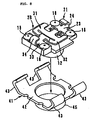
- Fig. 1 is an exploded perspective view showing the constitution of a coaxial connector according to an embodiment of the present invention.
- the coaxial connector 1 comprises an insulating case made of synthetic resin which is divided into an underside insulating case 2A and an upper side insulating case 2B, a fixed terminal 21, a movable terminal 31, and an outer terminal (outer conductor) 41 which are made of metal.
- the underside insulating case 2A has a substantially rectangular shape. Guiding protuberances 3 for positioning the upper side insulating case 2B are provided in the four corners on the upper face (dividing plane) of the case 2A, and relief portions 4 for accommodating the ribs 18 (see Fig. 2) of the upper side insulating case 2B are formed in the vicinity of the guiding protuberances 3.
- the rib relief portions 4 each have a concave plane shape, namely, a reverse dome-shape (see Fig. 10).
- rectangular cut-outs 6 and 7 are formed in the centers of the two opposed sides of the underside insulating case 2A, respectively. In the cut-out 6, the lead 24 of the fixed terminal 21 is received. On the other hand, the lead 34 of the movable terminal 31 is received in the cut-out 7.
- the upper side insulating case 2B contains a substantially rectangular cover 11 and a columnar introduction portion 12 in the center of the upper face of the cover 11.
- the columnar introduction portion 12 is opened in a cone-shape in the upper portion thereof, and has an introduction hole 13 having a circular cross-section.
- the introduction hole 13 extends through the upper side insulating case 2B. The center contact of a mating coaxial connector intrudes into the introduction hole 13 from the cone-shaped opening side.
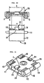
- the columnar ribs 18 are provided in the four corners on the bottom (dividing plane) of the upper side insulating case 2B as shown in Fig. 2. These ribs 18 are formed in order to position the fixed metallic terminal 21 and the movable terminal 31. The tops of the ribs 18 are worked so as to have a C-shaped plane, so that the terminals 21 and 31 can be easily guided.
- a groove 15 having a V-shaped cross section is formed between the introduction hole 13 and the side of the fixed terminal 21 from which the fixed terminal 21 is led out. The groove 15 is elongated perpendicularly to the leading-out direction of the metallic fixed terminal 21. The groove 15 has a function of preventing a flux contained in soldering paste from permeating into the insulating case.
- the fixed terminal 21 is formed by punching and bending a metallic flat sheet.
- the fixed terminal 21 comprises a contact portion 22 as a contact with the movable terminal 31, a fixed portion 23 fixedly sandwiched between the insulating cases 2A and 2B, and the lead 24 which is bent in an L-shape.
- the contact portion 22 is formed by bending both side portions thereof at a predetermined angle, and contains a horizontal plane 22a and inclined planes 22b on both of the sides of the horizontal plane 22a.
- the fixed portion 23 is provided with half-circular concavities 26 on both of the sides thereof.
- the concavities 26 are fitted onto the ribs 18 of the upper side insulating case 2B, respectively, so that the fixed terminal 21 is incorporated in the upper side insulating case 2B with a high positional accuracy.
- the upper side insulating case 2B is set in an assembly apparatus with the bottom side thereof being faced upward.
- the fixed terminal 21 is incorporated from the upper side of the upper side insulating case 2B so that the horizontal face 22a and the fixed portion 23 of the contact portion 22 come into close contact with the bottom of the upper side insulating case 2B.
- a gap is formed between the fixed terminal 21 and the groove 15 which intersect each other.
- FIG. 3 is a side view of the coaxial connector taken in the direction indicated by arrow K in Fig. 2.
- the top face 81a of the head chip 81 has a concave shape, namely, has a reversed dome shape.
- the head chip 81 is heated at a temperature at which the rib 18 can be deformed thermally sufficiently.
- the rib 18 is thermally deformed by the top 81a of the head chip 81 into a dome shape. Thereafter, the head chip 81 is elevated.
- the other rib 18 for positioning the fixed terminal 21 is thermally deformed into a dome shape.
- the fixed terminal 21 is heat welding-fixed to the bottom of the upper side insulating case 2B by means of the thermally deformed dome-shaped ribs 18.
- the movable terminal 31 (see Fig. 1) is formed by punching a metallic sheet having a spring property into a predetermined shape and size, and bending it.
- the movable terminal 31 is formed so as to have a spring-movable function, and comprises a movable contact portion 32 as a contact with the fixed terminal 21, a fixed portion 33 fixedly sandwiched between the insulating cases 2A and 2B, and a lead 34 bent into an L-shape.
- the movable contact portion 32 is bent so as to rise upward into an arc shape.
- Spring supports 37 are provided on both of the ends of the movable contact portion 32, and a spring contact portion 38 is formed in the center thereof.
- Half-circular concavities 36 are formed on both of the sides of the fixed portion 33.
- the concavities 36 are fixed onto the ribs 18 of the upper side insulating case 2B, respectively, as shown in Fig. 6, so that the movable terminal 31 is incorporated into the upper side insulating case 2B with a high positional accuracy. Then, the movable terminal 31 is incorporated from the upper direction of the upper side insulating case 2B set in an assembly apparatus with the bottom side of the case 2B facing upward, so that the fixed portion 33 comes in close contact with the bottom of the upper side insulating case 2B.
- head chips 81 of the welder are pushed against the two ribs 18 positioning the movable terminal 31, from the upper direction of the upper side insulating case 2B, in the same procedures as described in reference to Figs. 3 and 4, so that the ribs 18 are thermally deformed into a dome shape.
- the movable terminal 31 is heat welding-fixed to the bottom of the upper side insulating case 2B by means of the ribs 18 thermally deformed into a dome shape.
- the terminals 21 and 31 are fixed to the upper side insulating case 2B.
- the outer terminal 41 (see Fig. 1) to be in contact with the outer conductor of a mating coaxial connector is formed by punching a metal sheet, e.g., made of brass, spring-use phosphor bronze, or the like, bending, drawing, or the like.
- a flat portion 42 in the center of the sheet body is made to cover the upper face of the upper side insulating case 2B.
- Legs 43 are formed in the four corners of the flat portion 42, respectively.
- a cylindrical through-hole portion 45 is formed so as to be concentric with the columnar introduction portion 12 of the upper side insulating case 2B.
- the cylindrical through-hole portion 45 is fitted onto the outer conductor of the mating coaxial connector.
- the outer terminal 41 functions as a ground.
- the outer surface of the outer terminal 41 is plated, if necessary.
- the outer terminal 41 is set on an assembly apparatus with the bottom side thereof being faced upward. Then, the upper side insulating case 2B having the terminals 21 and 31 fixed thereto is conveyed to the upper position of the outer terminal 41 with the bottom side thereof being faced upward. Moreover, from the upper direction of the external terminal 41, the upper side insulating case 2B is overlaid and incorporated into the external terminal 41. That is, the columnar introduction portion 12 of the upper side insulating case 2B is fitted into the cylindrical through-hole portion 45 of the outer terminal 41. Thereafter, as shown in Fig. 9, the underside insulating case 2A is overlaid on the upper side insulating case 2B.
- Fig. 10 is a partial cross sectional view of the coaxial connector taken in the direction X-X in Fig. 9.
- the ribs 18 of the upper side insulating case 2B are thermally deformed to have a domed shape, and also, the rib relief portions 4 of the underside insulating case 2A are formed so as to have a reversed dome shape.
- the legs 43 of the outer terminal 41 are caulked from the upper direction to obtain an assembly having the structure in which the terminals 21 and 31 and the insulating case 2A and 2B are overlaid on each other as shown in Fig. 12. Thereby, the structure of the assembly becomes stiff.
- Fig. 13 is a perspective view of the coaxial connector 1 having a switching function, assembled as described above and viewed from the upper face direction thereof.
- the top portions of the leads 24 and 34 of the terminals 21, 31, and 41, and the legs 43 are formed so as to be substantially on the same plane as the bottom of the underside insulating case 2A.
- the coaxial connector 1 has such a structure that surface-mounting on the coaxial connector can be carried out.
- the cylindrical through-hole portion 45 is formed, so that secure, stable connection to the mating coaxial connector can be achieved.
- the fixed terminal 21 and the movable terminal 31 are arranged so that the fixed terminal 21 lies on the movable terminal 31.
- the fixed portions 23 and 33 are sandwiched between the insulating cases 2A and 2B, respectively.
- the positions of the terminals 21 and 31 are determined with respect to the insulating cases 2A and 2B.
- the terminals 21 and 31 can be easily fixed with respect to the insulating cases 2A and 2B.
- the fixed terminal 21 and the movable terminal 31 are formed as assemble parts separated from the insulating cases 2A and 2B, respectively, working of the parts can be achieved with less difficulty as compared with conventional assembled parts integrally formed by insert molding. Thus, the sum of the unit costs of the assembled parts 2A, 2B, 21, 31, and 41 becomes lower than that of the conventional parts.
- the respective assembled parts 2A, 2B, 21, 31 and 41 are overlaid on each other and incorporated sequentially while the work pieces are being sequentially fed. Accordingly, the finishing states of the work pieces in the respective processes can be checked, respectively. Thus, rejected products can be earlier detected in the respective processes, and the quality of the products can be enhanced. In addition, useless assembly of the rejected products is eliminated, so that the product cost can be reduced. Moreover, since the incorporation of the assembled parts 2A, 2B, 21, 31, and 41 is carried out in one direction (from the upper direction), the production efficiency can be more improved.
- the dome-shaped ribs 18 fix the terminals 21 and 31, and the upper side insulating case 2B beforehand. Accordingly, in the case in which the terminals 21 and 31 are sandwiched between the underside insulating case 2A and the upper side insulating case 2B, there is no danger that the terminals 21 and 31 are released or shifted from the terminals 21 and 31, which are caused by vibration or impact while the parts are conveyed in the production facilities.
- the sizes of the contact portion 22 of the fixed terminal 21 and the movable contact portion 32 of the movable terminal 31 are relatively small. Therefore, it is a large factor in enhancement of the mechanical performance (the spring performance of the movable contact portion 32) of the coaxial connector 1 that the contact positions of the contact portion 22 and the movable contact portion 32 are accurately determined.
- the contact position between the contact portion 22 and the movable contact portion 32 can be checked. Therefore, a deficiency in contact between the contact portion 22 and the movable contact portion 32 can be detected during assembly.
- the respective assembly parts 2A, 2B, 21, 31, and 41 are fixed by heat welding and caulking, not using a chemical material such as an adhesive, a solder, or the like. Accordingly, in the case in which the production line facilities are stopped for a moment for maintenance or the like, it is not necessary to consider degradation of the chemical material. Accordingly, the production line facilities can be quickly worked again.
- the center contact 65 of the mating coaxial connector inserted through the introduction hole 13 provided on the upper side pushes the center portion of the movable contact portion 32 downward so that the center portion is inverted and gets into the state that it extends downward into an arc shape.
- the spring contact portion 38 of the movable terminal 31 is released from the contact portion 22 of the fixed terminal 21, so that the electrical connection between the fixed terminal 21 and the movable terminal 31 is interrupted, while the center contact 65 and the movable terminal 31 are electrically connected to each other.
- the outer conductor (not shown) of the mating coaxial connector is fitted onto the outer terminal 41, so that the outer conductor and the outer terminal 41 are electrically connected to each other.
- the center portion of the movable contact portion 32 is restored to the state that the center portion rises upward, utilizing the spring property. Thereby, the fixed terminal 21 and the movable terminal 31 are electrically connected to each other again, while the electrical connection between the center contact 65 and the movable terminal 31 is interrupted.
- Fig. 16 shows an electric circuit block diagram of the RF circuit portion of a portable telephone 120.
- VCO voltage control oscillator
- the coaxial connector 1 of the first embodiment can be used as the change-over switch 125.
- a measuring probe (mating coaxial connector) 126 connected to a meter is fitted onto the coaxial connector 1.
- the signal path from the RF circuit portion to the antenna 122 can be changed to the signal path from the RF circuit portion to the meter.
- the measuring probe 126 is removed from the coaxial connector 1, the signal path is returned to the signal path from the RF circuit portion to the antenna 122.
- a portable telephone 120 having a high reliability can be realized by mounting the coaxial connector 1.
- the coaxial connector and the communications device having the same of the present invention are limited to the above embodiments, and can be differently modified within the scope of the present invention as defined in the annexed claims.
- the ribs formed on the insulating case may be provided on the upper side insulating case 2B as described in the above-described embodiments, or may be provided on the underside insulating case 2A.
- optional shapes and sizes such as rectangular and circular shapes may be selected in compliance with specifications.
- the fixed terminal and the movable terminal are formed as assembly parts separated from the insulating cases, respectively, working of the parts can be achieved with less difficulty as compared with that of conventional assembly parts integrally formed by insert molding. Accordingly, the sum of the unit costs of the respective assembly parts is smaller than that of the conventional assembly parts.
- the structure is employed in which the first resin member, the second resin member, the fixed terminal, the movable terminal, the external terminal are overlaid on each other, the assembly parts such as the terminals.
- the resin members, or the like are overlaid and incorporated sequentially while the work pieces are sequentially conveyed. Accordingly, even though the number of assembly parts is increased, the number of production processes can be suppressed. Furthermore, since the finishing states of the work-pieces in the respective processes, rejected products can be earlier detected in the respective processes. Thus, high quality products can be provided.
- the assembling of the assembly parts is carried out in one direction, and thereby, the production efficiency can be more improved.
Landscapes
- Coupling Device And Connection With Printed Circuit (AREA)
- Details Of Connecting Devices For Male And Female Coupling (AREA)
- Multi-Conductor Connections (AREA)
Abstract
Description
Claims (3)
- A coaxial connector comprising:a first resin member (2B) having a concave portion (13) into which a center contact of a mating coaxial connector is inserted;a second resin member (2A) for constituting an insulating case with the first resin member;a fixed terminal (21) and a movable terminal (31) fixed to one of the first resin member (2B) and the second resin member (2A); andan external terminal (41) mounted on the outside of the insulating case and electrically connected to an outer conductor of the mating coaxial connector,wherein the fixed terminal (21) and the movable terminal (31) are sandwiched between the first resin member (2B) and the second resin member (2A).
- A coaxial connector according to claim 1, wherein the coaxial connector has the structure in which the first resin member (2B), the second resin member (2A), the fixed terminal (21), the movable terminal (31), and the external terminal (41) are overlaid on each other, and assembling of the first resin member (2B), the second resin member (2A), the fixed terminal (21), the movable terminal (31), and the external terminal (41) is carried out in one direction.
- A communications device including the coaxial connector as set forth in claim 1 or 2.
Applications Claiming Priority (2)
| Application Number | Priority Date | Filing Date | Title |
|---|---|---|---|
| JP2000221399 | 2000-07-21 | ||
| JP2000221399A JP3473559B2 (en) | 2000-07-21 | 2000-07-21 | Coaxial connector, manufacturing method thereof, and communication device |
Publications (3)
| Publication Number | Publication Date |
|---|---|
| EP1174958A2 true EP1174958A2 (en) | 2002-01-23 |
| EP1174958A3 EP1174958A3 (en) | 2002-06-26 |
| EP1174958B1 EP1174958B1 (en) | 2004-12-15 |
Family
ID=18715808
Family Applications (1)
| Application Number | Title | Priority Date | Filing Date |
|---|---|---|---|
| EP01401979A Expired - Lifetime EP1174958B1 (en) | 2000-07-21 | 2001-07-23 | Coaxial connector and communication device having the same |
Country Status (6)
| Country | Link |
|---|---|
| US (1) | US6666699B2 (en) |
| EP (1) | EP1174958B1 (en) |
| JP (1) | JP3473559B2 (en) |
| KR (1) | KR100430178B1 (en) |
| CN (1) | CN1260989C (en) |
| DE (1) | DE60107771T2 (en) |
Cited By (1)
| Publication number | Priority date | Publication date | Assignee | Title |
|---|---|---|---|---|
| WO2010008884A1 (en) * | 2008-06-24 | 2010-01-21 | Molex Incorporated | Electric connector |
Families Citing this family (20)
| Publication number | Priority date | Publication date | Assignee | Title |
|---|---|---|---|---|
| US6843673B1 (en) * | 2004-04-30 | 2005-01-18 | Speed Tech Corp. | Coaxial connector structure |
| US6939152B1 (en) * | 2004-07-20 | 2005-09-06 | Su-Lien Chen | Microswitch connector |
| JP4220446B2 (en) | 2004-08-27 | 2009-02-04 | ヒロセ電機株式会社 | Coaxial connector with switch |
| WO2006059578A1 (en) * | 2004-12-03 | 2006-06-08 | Murata Manufacturing Co., Ltd. | Electric contact part, coaxial connector, and electric circuit device using the part and the connector |
| KR100646826B1 (en) | 2005-07-29 | 2006-11-23 | 케이. 에이. 이 (주) | Coaxial connector for DMX receiving antenna of mobile communication terminal |
| CN100466401C (en) * | 2006-07-20 | 2009-03-04 | 宣德科技股份有限公司 | Manufacturing method of radio frequency connector |
| US7351067B2 (en) * | 2006-08-09 | 2008-04-01 | Speed Tech Corp. | Coaxial cable connecting apparatus |
| DE102007051101A1 (en) * | 2007-10-24 | 2009-10-08 | Ims Connector Systems Gmbh | Microswitch for a coaxial connector |
| ATE557453T1 (en) | 2008-06-25 | 2012-05-15 | Murata Manufacturing Co | COAXIAL PLUG |
| JP5402718B2 (en) * | 2010-02-25 | 2014-01-29 | 株式会社村田製作所 | connector |
| JP5532041B2 (en) * | 2011-10-21 | 2014-06-25 | 第一精工株式会社 | Coaxial connector with switch |
| TWI470881B (en) * | 2012-08-09 | 2015-01-21 | Murata Manufacturing Co | Coaxial connector |
| JP5904283B2 (en) | 2012-08-24 | 2016-04-13 | 株式会社村田製作所 | Coaxial connector |
| JP5964259B2 (en) | 2013-02-08 | 2016-08-03 | 株式会社村田製作所 | Coaxial connector |
| CN103811925B (en) * | 2013-03-13 | 2016-03-02 | 深圳市长盈精密技术股份有限公司 | Switching mode coaxial connector |
| DE112014001758B4 (en) * | 2013-03-29 | 2020-11-12 | The Yokohama Rubber Co., Ltd. | Use of a rubber composition for producing a heavy duty pneumatic tire and heavy duty pneumatic tire made therefrom |
| CN104752850B (en) * | 2013-12-31 | 2017-11-07 | 电连技术股份有限公司 | It is low to match somebody with somebody signal connector |
| CN103915703B (en) * | 2014-03-05 | 2019-09-20 | 连展科技电子(昆山)有限公司 | Miniature radio-frequency connector |
| CN109149173B (en) * | 2017-06-28 | 2021-06-04 | 中航光电科技股份有限公司 | Inter-board connector and socket thereof |
| JP7838547B2 (en) * | 2023-09-06 | 2026-04-01 | 株式会社村田製作所 | Switch connector |
Family Cites Families (20)
| Publication number | Priority date | Publication date | Assignee | Title |
|---|---|---|---|---|
| DE8235915U1 (en) * | 1982-12-21 | 1983-04-14 | Siemens AG, 1000 Berlin und 8000 München | COAXIAL CONNECTOR |
| JPH0436065Y2 (en) * | 1984-12-30 | 1992-08-26 | ||
| FR2642232B1 (en) * | 1989-01-20 | 1993-09-03 | Alliance Tech Ind | ULTRA MINIATURE CONNECTION INTERFACE FOR HIGH FREQUENCY |
| JPH07135053A (en) * | 1993-11-08 | 1995-05-23 | Murata Mfg Co Ltd | Coaxial connector and coaxial connector mounting structure |
| US5563562A (en) * | 1995-03-24 | 1996-10-08 | Itt Industries, Inc. | RF feed-through connector |
| US6074217A (en) * | 1995-05-25 | 2000-06-13 | Murata Manufacturing Co., Ltd. | Coaxial connector receptacle |
| GB2307113B (en) * | 1995-11-08 | 1999-04-28 | Itt Ind Ltd | Improvements in or relating to coaxial connectors |
| FR2743200B1 (en) * | 1995-12-28 | 1998-01-23 | Alcatel Mobile Comm France | SWITCHED CONNECTOR FOR RADIOCOMMUNICATION TERMINAL AND RELATED CONNECTION SOCKET |
| JP3554948B2 (en) * | 1996-02-29 | 2004-08-18 | 株式会社村田製作所 | Coaxial connector |
| JP3064906B2 (en) * | 1996-06-12 | 2000-07-12 | 株式会社村田製作所 | Coaxial connector |
| US5741146A (en) * | 1996-10-29 | 1998-04-21 | The Whitaker Corporation | Coaxial switch |
| JP3079274B2 (en) * | 1997-05-12 | 2000-08-21 | エスエムケイ株式会社 | Coaxial connector with switch |
| JP3551770B2 (en) * | 1998-01-13 | 2004-08-11 | 株式会社村田製作所 | Coaxial connector |
| JP2889562B1 (en) * | 1998-04-21 | 1999-05-10 | エスエムケイ株式会社 | Coaxial connector with switch |
| JP3337650B2 (en) * | 1998-10-05 | 2002-10-21 | ヒロセ電機株式会社 | Coaxial connector with switch |
| JP2002531926A (en) * | 1998-12-02 | 2002-09-24 | エフシーアイ | Connector with switching device |
| JP2001015226A (en) | 1999-06-30 | 2001-01-19 | Matsushita Electric Ind Co Ltd | Coaxial connector switch |
| JP3346360B2 (en) | 1999-12-21 | 2002-11-18 | 株式会社村田製作所 | Electronic components, coaxial connectors and communication equipment |
| JP3473531B2 (en) | 2000-01-07 | 2003-12-08 | 株式会社村田製作所 | Coaxial connector and communication device |
| US6217382B1 (en) * | 2000-01-20 | 2001-04-17 | Hughes Electronics Corporation | Coaxial cable ESD bleed |
-
2000
- 2000-07-21 JP JP2000221399A patent/JP3473559B2/en not_active Expired - Lifetime
-
2001
- 2001-07-20 CN CN01125198.0A patent/CN1260989C/en not_active Expired - Lifetime
- 2001-07-20 KR KR10-2001-0043772A patent/KR100430178B1/en not_active Expired - Lifetime
- 2001-07-23 US US09/910,977 patent/US6666699B2/en not_active Expired - Lifetime
- 2001-07-23 DE DE60107771T patent/DE60107771T2/en not_active Expired - Lifetime
- 2001-07-23 EP EP01401979A patent/EP1174958B1/en not_active Expired - Lifetime
Cited By (1)
| Publication number | Priority date | Publication date | Assignee | Title |
|---|---|---|---|---|
| WO2010008884A1 (en) * | 2008-06-24 | 2010-01-21 | Molex Incorporated | Electric connector |
Also Published As
| Publication number | Publication date |
|---|---|
| CN1335735A (en) | 2002-02-13 |
| US6666699B2 (en) | 2003-12-23 |
| CN1260989C (en) | 2006-06-21 |
| DE60107771D1 (en) | 2005-01-20 |
| JP2002042991A (en) | 2002-02-08 |
| JP3473559B2 (en) | 2003-12-08 |
| KR100430178B1 (en) | 2004-05-04 |
| DE60107771T2 (en) | 2005-11-24 |
| EP1174958B1 (en) | 2004-12-15 |
| KR20020008777A (en) | 2002-01-31 |
| US20020009912A1 (en) | 2002-01-24 |
| EP1174958A3 (en) | 2002-06-26 |
Similar Documents
| Publication | Publication Date | Title |
|---|---|---|
| EP1174958B1 (en) | Coaxial connector and communication device having the same | |
| US6099334A (en) | Coaxial connector with switch | |
| US6783374B2 (en) | Electronic component, coaxial connector, and communication device | |
| US6751317B2 (en) | Movable terminal, coaxial connector, and communication apparatus incorporating the same | |
| US6554630B2 (en) | Movable terminal, coaxial connector, and communication apparatus | |
| EP1174960B1 (en) | Coaxial connector and communication device having the same | |
| KR20040015375A (en) | Connector with switching function | |
| KR20130126501A (en) | Coaxial connector attached with switch | |
| US6968609B2 (en) | Nonreciprocal circuit device, communication device, and method of manufacturing nonreciprocal circuit device | |
| JP2025003114A (en) | Electrical connector and method for manufacturing contact pins of the electrical connector | |
| JP2025003112A (en) | Electrical connector and method for manufacturing contact pins of the electrical connector | |
| KR101248843B1 (en) | Rf switch |
Legal Events
| Date | Code | Title | Description |
|---|---|---|---|
| PUAI | Public reference made under article 153(3) epc to a published international application that has entered the european phase |
Free format text: ORIGINAL CODE: 0009012 |
|
| 17P | Request for examination filed |
Effective date: 20010727 |
|
| AK | Designated contracting states |
Kind code of ref document: A2 Designated state(s): AT BE CH CY DE DK ES FI FR GB GR IE IT LI LU MC NL PT SE TR |
|
| AX | Request for extension of the european patent |
Free format text: AL;LT;LV;MK;RO;SI |
|
| PUAL | Search report despatched |
Free format text: ORIGINAL CODE: 0009013 |
|
| AK | Designated contracting states |
Kind code of ref document: A3 Designated state(s): AT BE CH CY DE DK ES FI FR GB GR IE IT LI LU MC NL PT SE TR |
|
| AX | Request for extension of the european patent |
Free format text: AL;LT;LV;MK;RO;SI |
|
| AKX | Designation fees paid |
Designated state(s): DE FR GB |
|
| 17Q | First examination report despatched |
Effective date: 20030224 |
|
| GRAP | Despatch of communication of intention to grant a patent |
Free format text: ORIGINAL CODE: EPIDOSNIGR1 |
|
| GRAS | Grant fee paid |
Free format text: ORIGINAL CODE: EPIDOSNIGR3 |
|
| GRAA | (expected) grant |
Free format text: ORIGINAL CODE: 0009210 |
|
| AK | Designated contracting states |
Kind code of ref document: B1 Designated state(s): DE FR GB |
|
| REG | Reference to a national code |
Ref country code: GB Ref legal event code: FG4D |
|
| REG | Reference to a national code |
Ref country code: IE Ref legal event code: FG4D |
|
| REF | Corresponds to: |
Ref document number: 60107771 Country of ref document: DE Date of ref document: 20050120 Kind code of ref document: P |
|
| PLBE | No opposition filed within time limit |
Free format text: ORIGINAL CODE: 0009261 |
|
| STAA | Information on the status of an ep patent application or granted ep patent |
Free format text: STATUS: NO OPPOSITION FILED WITHIN TIME LIMIT |
|
| 26N | No opposition filed |
Effective date: 20050916 |
|
| ET | Fr: translation filed | ||
| REG | Reference to a national code |
Ref country code: FR Ref legal event code: PLFP Year of fee payment: 16 |
|
| REG | Reference to a national code |
Ref country code: FR Ref legal event code: PLFP Year of fee payment: 17 |
|
| REG | Reference to a national code |
Ref country code: FR Ref legal event code: PLFP Year of fee payment: 18 |
|
| PGFP | Annual fee paid to national office [announced via postgrant information from national office to epo] |
Ref country code: FR Payment date: 20200721 Year of fee payment: 20 Ref country code: DE Payment date: 20200721 Year of fee payment: 20 Ref country code: GB Payment date: 20200727 Year of fee payment: 20 |
|
| REG | Reference to a national code |
Ref country code: DE Ref legal event code: R071 Ref document number: 60107771 Country of ref document: DE |
|
| REG | Reference to a national code |
Ref country code: GB Ref legal event code: PE20 Expiry date: 20210722 |
|
| PG25 | Lapsed in a contracting state [announced via postgrant information from national office to epo] |
Ref country code: GB Free format text: LAPSE BECAUSE OF EXPIRATION OF PROTECTION Effective date: 20210722 |