EP1174859A2 - Write head fault detection circuit and method - Google Patents
Write head fault detection circuit and method Download PDFInfo
- Publication number
- EP1174859A2 EP1174859A2 EP01000314A EP01000314A EP1174859A2 EP 1174859 A2 EP1174859 A2 EP 1174859A2 EP 01000314 A EP01000314 A EP 01000314A EP 01000314 A EP01000314 A EP 01000314A EP 1174859 A2 EP1174859 A2 EP 1174859A2
- Authority
- EP
- European Patent Office
- Prior art keywords
- write head
- voltage
- threshold voltage
- coil
- nodes
- Prior art date
- Legal status (The legal status is an assumption and is not a legal conclusion. Google has not performed a legal analysis and makes no representation as to the accuracy of the status listed.)
- Granted
Links
- 238000001514 detection method Methods 0.000 title claims abstract description 66
- 238000000034 method Methods 0.000 title claims abstract description 17
- 230000008878 coupling Effects 0.000 claims description 6
- 238000010168 coupling process Methods 0.000 claims description 6
- 238000005859 coupling reaction Methods 0.000 claims description 6
- 230000001052 transient effect Effects 0.000 claims description 5
- 238000010586 diagram Methods 0.000 description 6
- 238000013461 design Methods 0.000 description 5
- 238000004088 simulation Methods 0.000 description 3
- 238000004458 analytical method Methods 0.000 description 2
- 230000003466 anti-cipated effect Effects 0.000 description 2
- 230000001419 dependent effect Effects 0.000 description 2
- 238000012544 monitoring process Methods 0.000 description 2
- 238000004364 calculation method Methods 0.000 description 1
- 230000001939 inductive effect Effects 0.000 description 1
- 230000002045 lasting effect Effects 0.000 description 1
- 238000004519 manufacturing process Methods 0.000 description 1
- 238000012986 modification Methods 0.000 description 1
- 230000004048 modification Effects 0.000 description 1
- 230000008569 process Effects 0.000 description 1
- 238000012546 transfer Methods 0.000 description 1
- 230000007704 transition Effects 0.000 description 1
Images


Classifications
-
- G—PHYSICS
- G11—INFORMATION STORAGE
- G11B—INFORMATION STORAGE BASED ON RELATIVE MOVEMENT BETWEEN RECORD CARRIER AND TRANSDUCER
- G11B20/00—Signal processing not specific to the method of recording or reproducing; Circuits therefor
- G11B20/02—Analogue recording or reproducing
-
- G—PHYSICS
- G11—INFORMATION STORAGE
- G11B—INFORMATION STORAGE BASED ON RELATIVE MOVEMENT BETWEEN RECORD CARRIER AND TRANSDUCER
- G11B5/00—Recording by magnetisation or demagnetisation of a record carrier; Reproducing by magnetic means; Record carriers therefor
- G11B5/455—Arrangements for functional testing of heads; Measuring arrangements for heads
-
- G—PHYSICS
- G11—INFORMATION STORAGE
- G11B—INFORMATION STORAGE BASED ON RELATIVE MOVEMENT BETWEEN RECORD CARRIER AND TRANSDUCER
- G11B5/00—Recording by magnetisation or demagnetisation of a record carrier; Reproducing by magnetic means; Record carriers therefor
- G11B2005/0002—Special dispositions or recording techniques
- G11B2005/0005—Arrangements, methods or circuits
- G11B2005/001—Controlling recording characteristics of record carriers or transducing characteristics of transducers by means not being part of their structure
- G11B2005/0013—Controlling recording characteristics of record carriers or transducing characteristics of transducers by means not being part of their structure of transducers, e.g. linearisation, equalisation
-
- G—PHYSICS
- G11—INFORMATION STORAGE
- G11B—INFORMATION STORAGE BASED ON RELATIVE MOVEMENT BETWEEN RECORD CARRIER AND TRANSDUCER
- G11B5/00—Recording by magnetisation or demagnetisation of a record carrier; Reproducing by magnetic means; Record carriers therefor
- G11B5/012—Recording on, or reproducing or erasing from, magnetic disks
Definitions
- the present invention generally relates to the field of information storage, and more particularly to a circuit and method for detecting faults on a write head of a hard-disk drive.
- Hard-disk drives are mass storage devices that may include a magnetic storage media, e.g., rotating disk or platters, a spindle motor, read/write heads, an actuator, a preamplifier, a read channel, a write channel, a servo circuit and control circuitry to control the operation of the hard-disk drive and to properly interface the hard-disk drive to a host system or bus.
- Figure 1 shows an example of a prior art disk drive mass storage system 10.
- Disk drive system 10 includes a number of rotating platters 12 mounted on a base.
- Platters 12 are used to store data that is represented as magnetic transitions on the magnetic platters 12, with each platter 12 coupleable to an arm 14 having a read head 16 and a write head 18 at the tip thereof.
- the read head 16 and write head 18 are adapted to transfer data to and from the platters 12 via a preamplifier 20.
- the preamplifier 20 is coupled to circuitry 22 that processes the data being read from and written to platters 12 and controls the various operations of disk drive system 10.
- the read heads 16 comprise magnetoresistive heads adapted to read data from platters 12 when current is passed through them.
- the write heads 18 comprise inductive wires (coils) that transmit data to magnetic media platters 12. Heads 16, 18 are coupled to preamplifier 20 that serves as an interface between read/write heads 16/18 of disk drive system 10 and circuitry 22.
- the preamp 20 may comprise a single chip containing a reader amplifier, a writer circuit, fault detection circuitry, and a serial port interface, for example.
- the write head 18 comprises a coil through which current is passed to create a magnetic field and write data onto platters 12.
- a problem in hard-disk drive systems 10 is that the write head 18 coil may be open or short at various times during manufacturing or in the field for a variety of reasons. The open or short faults may occur due to a faulty coil that has severed, creating an open circuit, or a faulty coil that has fused together, creating a short circuit. If the hard-disk drive is moved, the vibration may cause the write head coil to temporarily short to ground, for example. In any of these situations, the write head fault needs to be reported immediately, for example, from preamplifier 20 to circuitry 22. If the write head 18 coil is permanently damaged, it needs to be repaired or replaced. Furthermore, the electrical resistance of the write head 18 coil may be too high to function properly.
- a hard-disk drive system 10 requires a function to detect write head 18 faults.
- Prior art write fault detection methods typically are performed during the write mode, a very noisy mode.
- a hard-disk drive system 10 has two active operating modes: a read mode during which data is read from platters 12 via read heads 16, and a write mode, during which write heads 18 write data to platters 12.
- the preamplifier 20 includes control circuitry for- both the read head 16 and the write head 18. Therefore, it has two exclusive active operation modes: read and write.
- the read mode is a more passive, quiet and steady mode, and the write mode is more of an active mode because a large amount of current (usually around 30 to 70 mA), with the current polarity being switched frequently, for example, every 1 or 2 nanoseconds, is passed through the coil in order to write data to platters 12.
- the preamplifier 20 provides a substantial current to write head 18 coil to create a magnetic field that writes data to the platters 12. More recent designs of hard-disk drive systems 10 have higher data rates such as 1 gigabits per second, and the write current has to switch direction or polarity faster, accordingly. This results in a complicated write signal waveform, making it difficult to detect write head faults correctly. For example, when the write head is operating normally at high data rate, prior art methods of detecting write head faults may give a false detection and indicate that the write head has an open fault or short to ground. Alternatively, write head faults may not be detected with prior art detection circuits and methods due to their limited frequency range for correct operation.
- the present invention provides an accurate circuit and method for detecting write head faults in a disk drive circuit.
- the fault detection is performed during a read mode using a small DC current, avoiding problems that arise when performing a write head fault detection during the write mode of a hard-disk drive.
- Several devices that may be pre-existing in a writer circuit are used to build the present DC detection circuit, which provides reliable and accurate write fault detection while minimizing the circuit overhead needed to perform the write head fault detection function.
- a first and second serially connected resistor having equal values are coupled across the coil of the write head, with a transistor coupled to a common node between the two resistors and ground to maintain a DC current path to ground. The voltages across the two resistors and with respect to the common node are analyzed to determine the fault status of the write head coil.
- the circuit includes a first resistor coupled to a first end of the write head coil at a node "a”, and a second resistor coupled to a second end of the coil at a node "b".
- a transistor is coupled to the first and second resistors at a common node "c”. Faults on the write head coil are detectable by analyzing the voltages across the nodes "a", "b” and "c".
- Also disclosed is a method of detecting faults on a write head of a hard-disk drive comprises the steps of coupling a first end of the write head coil to a first resistor at a node "a”, coupling a second end of the coil to a second resistor at a node "b”, and coupling a transistor to the first and second resistors at a common node "c". Faults are detected on the coil by analyzing the voltages across nodes "a”, "b” and "c”.
- the present invention provides a reliable, accurate means of detecting faults on a write head of a disk drive system by performing a write head fault detection during a quiet operating mode of the hard-disk drive. Errors in write head fault detection are avoided by use of the present invention. Standard components are utilized that are inexpensive and easily implementable into electronic circuitry. The invention is advantageous in discriminating between an open or short fault, which is not possible with prior art fault detection circuits.
- the write head fault detection is frequency-independent because the detection is performed during a non-writing mode. Transient faults with short duration ( ⁇ 150 nanoseconds) are ignored by means of a timing delay.
- Write head fault detection circuit 30 comprises a first resistor R 1 coupled to coil L of a write head 18 of a hard-disk drive system at a node "a".
- a second resistor R 2 of equal value to R 1 is coupled to the other end of coil L at node "b".
- Resistors R 1 and R 2 are coupled together at a common node "c".
- Node "c" is also coupled to a switch shown as the source of MOS transistor Q 1 , but which may also comprise a low-power Schottky BJT transistor, for example.
- the gate of transistor Q 1 is coupled to control logic voltage V 0 and the source/emitter of transistor Q 1 coupled to ground.
- Node "c” is coupled to ground via transistor Q1.
- Transistor Q1 coupled between ground and the common node “c” of resistors R 1 and R 2 maintains a DC current path to ground.
- Coil L is characterized by a relatively small resistance r for the purposes of discussion rather than by an inductance because a DC current is used to detect faults on the coil.
- the detected voltage V ab across nodes "a" and "b" is equal to 1 ⁇ 2I 0 r when the coil resistance r is much less than resistance R, indicating that the coil is normal (e.g. has no faults).
- the detected Voltage V ab is equal to I 0 R when coil resistance r is much greater than resistance R, indicating an open fault in the coil L of the write head 18.
- Figure 3 shows a schematic diagram with specific values indicated for the components of the write head fault detection circuit 30 and additional components Q 2 , Q 3 , Q 4 , Q 5 , Q 6 , Q 7 , R 3 , R 4 and V 1 coupled to Q 1 , R 1 , R 2 and write head coil L as shown.
- the calculated voltage V ab across nodes "a” and “b” is equal to 4.5 mV.
- the calculated voltage V ab is 0 mV.
- the calculated voltage V ab 9 mV. If there is an open fault on coil L, the calculated voltage V ab is 750 mV.
- the chart may be read and interpreted for the voltage V ac across nodes "a" and "c”.
- Tables 2 and 3 are derived from the simulation calculation results of Table 1.
- Table 2 illustrates the monitoring and analysis of voltage V ab in accordance with the present invention to detect write head open faults.
- Write head status V yx (V ab ) No open fault ⁇ 10 mV Open fault 750 mV If voltage V ab is greater than a first threshold voltage, for example, 750 mV, an open fault is detected by write head fault detection circuit 30. If voltage V ab is less than a second threshold voltage, for example, 10 mV, then a normal write head status is detected.
- V ab is preferably used for detecting an open fault so that only two detection levels are required on voltage V ab .
- the actual values for the first and second threshold voltages are dependent on the component, voltage and current values of write head fault detection circuit 30; however, preferably the second threshold voltage is at least 10 times the order of magnitude of the first threshold voltage to insure accurate open fault detection.
- Table 3 illustrates the monitoring and analysis of voltage V ac in accordance with the present invention to detect write head shorts to ground.
- V ac is preferably used for detecting a short-to-ground fault so that only two detection levels are required on voltage V ac .
- the actual values for the third and fourth threshold voltages are dependent on the component, voltage and current values of write head fault detection circuit 30; however, preferably the second threshold voltage is at least 10 times the order of magnitude of the first threshold voltage to insure accurate short-to-ground write head fault detection.
- the fault detection circuit 30 detects whether a write head fault is a short or an open fault.
- voltage V ab is used for open fault detection
- voltage V ac is used for short fault detection, although other information may be obtained by analyzing both voltages V ab and V ac , using multiple threshold levels, as illustrated in Table 1.
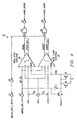
- Figure 4 shows a schematic for a voltage detection logic circuit 32 of the present invention, comprising a write open detection comparator 34 and write short detection comparator 36 coupled to nodes a (signal HY), b (signal HX) and c (signal HZ) for detecting and analyzing voltages V ab and V ac .
- Schematic 32 is exemplary of a preferred embodiment of the present invention, although other logic circuit designs or software algorithms are anticipated.
- Signal write open/short enable fault delay WOPSH_ENZ_F_DLY establishes a delay when the chip switches from write to read mode. This gives enough time for the writer circuit to settle down so that reliable and accurate detection can be done and no false faults will be reported.
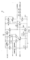
- Figure 5 shows a schematic of a preferred design for comparator 34, although other comparator designs are anticipated.
- Comparator 36 may comprise a similar architecture with different values for transistors M21, M22, and M23 at the output, for example.
- Figure 6 illustrates a hard-disk drive system 70 having a preamplifier 72 including the write head fault detection circuit 30 or 40 of the present invention.
- FIG. 7 shows a timing diagram 60 for the write head fault detection circuit 30 of the present invention showing transient faults of the write head coil L.
- Signal 62 indicates the fault duration T0 lasting from time t 0 to t 2
- the time period T2 from t 0 to t 1 indicates the detection time, or amount of time it takes for the write head fault detection circuit 30 to detect a fault on write head 18 coil L, which may be, for example 50ns.
- Signal 64 indicates the time period during which a fault is detected, from time periods from t 1 to t 4 .
- Time period T1 from t 2 to t 4 is the detection release time.
- Signal 66 indicates a fault detected delay signal of a predetermined time period.
- the detection delay time T3 is indicated by the time period between time t 1 and t 3 , which is usually based on disk drive 70 system requirements and may be, for example, 150 to 200 nanoseconds.
- signal 68 indicates a valid fault detection output, which indicates an open coil L or short coil L.
- the fault duration signal 62 must be long enough to be reported at the fault detection output, signal 68. This means that either: T0 + T1 > T2 +T3 or T0 >T2 + T3 - T1 in order for the fault detection circuit 30, 40 to report a fault output.
- T1 89.3 ns
- T2 47.8 ns
- T3 203 ns
- T1 71.7 ns
- T2 76.7 ns
- T3 148 ns
- the present invention provides a reliable, accurate means of detecting faults on a write head 18 of a hard-disk drive system 70. Rather than a dynamic fault detection during a write mode, a DC fault detection is performed during a quiet mode of the hard-disk drive 70 such as during the read mode. Errors in write head fault detection are avoided by use of the present invention. Standard components are utilized that are inexpensive and easily implementable into electronic circuitry. Some pre-existing components may be used for the fault detection circuit 30, and few additional components are required. The invention is preferably implemented in a preamplifier circuit 72. The invention is advantageous in discriminating between an open or short fault of a write head, which is not possible with prior art fault detection circuits.
- the write head fault detection is frequency-independent because the detection is performed during a non-writing mode. Short duration transient faults are ignored by means of a timing delay, preventing fault detection when the write head hits the storage media platter 12 for a short period due to mechanical vibration, for example.
Landscapes
- Engineering & Computer Science (AREA)
- Signal Processing (AREA)
- Digital Magnetic Recording (AREA)
- Recording Or Reproducing By Magnetic Means (AREA)
Abstract
Description
- The present invention generally relates to the field of information storage, and more particularly to a circuit and method for detecting faults on a write head of a hard-disk drive.
- Hard-disk drives are mass storage devices that may include a magnetic storage media, e.g., rotating disk or platters, a spindle motor, read/write heads, an actuator, a preamplifier, a read channel, a write channel, a servo circuit and control circuitry to control the operation of the hard-disk drive and to properly interface the hard-disk drive to a host system or bus. Figure 1 shows an example of a prior art disk drive mass storage system 10. Disk drive system 10 includes a number of rotating platters 12 mounted on a base. Platters 12 are used to store data that is represented as magnetic transitions on the magnetic platters 12, with each platter 12 coupleable to an arm 14 having a read head 16 and a write head 18 at the tip thereof. The read head 16 and write head 18 are adapted to transfer data to and from the platters 12 via a preamplifier 20. The preamplifier 20 is coupled to circuitry 22 that processes the data being read from and written to platters 12 and controls the various operations of disk drive system 10.
- Data is stored to and retrieved from each side of magnetic platters by write heads 18 and read heads 16, respectively, at the tip of arms 14. The read heads 16 comprise magnetoresistive heads adapted to read data from platters 12 when current is passed through them. The write heads 18 comprise inductive wires (coils) that transmit data to magnetic media platters 12. Heads 16, 18 are coupled to preamplifier 20 that serves as an interface between read/write heads 16/18 of disk drive system 10 and circuitry 22. The preamp 20 may comprise a single chip containing a reader amplifier, a writer circuit, fault detection circuitry, and a serial port interface, for example.
- The write head 18 comprises a coil through which current is passed to create a magnetic field and write data onto platters 12. A problem in hard-disk drive systems 10 is that the write head 18 coil may be open or short at various times during manufacturing or in the field for a variety of reasons. The open or short faults may occur due to a faulty coil that has severed, creating an open circuit, or a faulty coil that has fused together, creating a short circuit. If the hard-disk drive is moved, the vibration may cause the write head coil to temporarily short to ground, for example. In any of these situations, the write head fault needs to be reported immediately, for example, from preamplifier 20 to circuitry 22. If the write head 18 coil is permanently damaged, it needs to be repaired or replaced. Furthermore, the electrical resistance of the write head 18 coil may be too high to function properly.
- Because these faults in the write head 18 coil can occur, a hard-disk drive system 10 requires a function to detect write head 18 faults. Prior art write fault detection methods typically are performed during the write mode, a very noisy mode. Typically, a hard-disk drive system 10 has two active operating modes: a read mode during which data is read from platters 12 via read heads 16, and a write mode, during which write heads 18 write data to platters 12. The preamplifier 20 includes control circuitry for- both the read head 16 and the write head 18. Therefore, it has two exclusive active operation modes: read and write.
- The read mode is a more passive, quiet and steady mode, and the write mode is more of an active mode because a large amount of current (usually around 30 to 70 mA), with the current polarity being switched frequently, for example, every 1 or 2 nanoseconds, is passed through the coil in order to write data to platters 12.
- During the write mode, the preamplifier 20 provides a substantial current to write head 18 coil to create a magnetic field that writes data to the platters 12. More recent designs of hard-disk drive systems 10 have higher data rates such as 1 gigabits per second, and the write current has to switch direction or polarity faster, accordingly. This results in a complicated write signal waveform, making it difficult to detect write head faults correctly. For example, when the write head is operating normally at high data rate, prior art methods of detecting write head faults may give a false detection and indicate that the write head has an open fault or short to ground. Alternatively, write head faults may not be detected with prior art detection circuits and methods due to their limited frequency range for correct operation.
- The present invention provides an accurate circuit and method for detecting write head faults in a disk drive circuit. The fault detection is performed during a read mode using a small DC current, avoiding problems that arise when performing a write head fault detection during the write mode of a hard-disk drive. Several devices that may be pre-existing in a writer circuit are used to build the present DC detection circuit, which provides reliable and accurate write fault detection while minimizing the circuit overhead needed to perform the write head fault detection function. A first and second serially connected resistor having equal values are coupled across the coil of the write head, with a transistor coupled to a common node between the two resistors and ground to maintain a DC current path to ground. The voltages across the two resistors and with respect to the common node are analyzed to determine the fault status of the write head coil.
- Disclosed is a circuit for detecting faults on a write head of a hard-disk drive. The circuit includes a first resistor coupled to a first end of the write head coil at a node "a", and a second resistor coupled to a second end of the coil at a node "b". A transistor is coupled to the first and second resistors at a common node "c". Faults on the write head coil are detectable by analyzing the voltages across the nodes "a", "b" and "c".
- Also disclosed is a method of detecting faults on a write head of a hard-disk drive. The method comprises the steps of coupling a first end of the write head coil to a first resistor at a node "a", coupling a second end of the coil to a second resistor at a node "b", and coupling a transistor to the first and second resistors at a common node "c". Faults are detected on the coil by analyzing the voltages across nodes "a", "b" and "c".
- The present invention provides a reliable, accurate means of detecting faults on a write head of a disk drive system by performing a write head fault detection during a quiet operating mode of the hard-disk drive. Errors in write head fault detection are avoided by use of the present invention. Standard components are utilized that are inexpensive and easily implementable into electronic circuitry. The invention is advantageous in discriminating between an open or short fault, which is not possible with prior art fault detection circuits. The write head fault detection is frequency-independent because the detection is performed during a non-writing mode. Transient faults with short duration (< 150 nanoseconds) are ignored by means of a timing delay.
- For a more complete understanding of the present invention, and the advantages thereof, reference is now made to the following detailed description of certain particular and illustrative embodiments and the features and aspects thereof, by way of example only, and with reference to the figures of the accompanying drawings in which:
- Figure 1 illustrates a hard-disk drive system of the prior art;
- Figure 2 is a schematic diagram of an illustrative embodiment of the best mode of the write head fault detection circuit;
- Figure 3 is a schematic illustration of current, voltage and resistance values;
- Figure 4 shows a schematic diagram of a logic circuit having two comparators for write open and short detection;
- Figure 5 shows a schematic diagram of the write open detection comparator of the logic circuit;
- Figure 6 illustrates the present invention implemented in a hard-disk drive system; and
- Figure 7 shows a timing diagram for the fault detection function of write head fault circuit.
-
- Like numerals and symbols are employed in different figures to designate similar components in various views unless otherwise indicated.
- Figure 2 illustrates an exemplary embodiment of the best mode of the present invention. Write head fault detection circuit 30 comprises a first resistor R1 coupled to coil L of a write head 18 of a hard-disk drive system at a node "a". A second resistor R2 of equal value to R1 is coupled to the other end of coil L at node "b". Resistors R1 and R2 are coupled together at a common node "c". Node "c" is also coupled to a switch shown as the source of MOS transistor Q1, but which may also comprise a low-power Schottky BJT transistor, for example. The gate of transistor Q1 is coupled to control logic voltage V0 and the source/emitter of transistor Q1 coupled to ground. Node "c" is coupled to ground via transistor Q1. Transistor Q1 coupled between ground and the common node "c" of resistors R1 and R2 maintains a DC current path to ground. Coil L is characterized by a relatively small resistance r for the purposes of discussion rather than by an inductance because a DC current is used to detect faults on the coil.
- During a quiet mode of a hard-disk drive system such as the read mode, an initial DC current I0, preferably less than 0.5 mA is input into node "a". Because the resistance r of the coil L is substantially small with respect to the resistance of resistors R1 and R2 (R2=R1 >>r) , when the coil L is normal (has no faults), the current that flows through each of resistors R1 and R2 is approximately 0.5I0. Analyzing the voltages across the various nodes of the write head fault detection circuit 30 results in the following equations:where R = R1 = R2. The detected voltage Vab across nodes "a" and "b" is equal to ½I0r when the coil resistance r is much less than resistance R, indicating that the coil is normal (e.g. has no faults). The detected Voltage Vab is equal to I0R when coil resistance r is much greater than resistance R, indicating an open fault in the coil L of the write head 18.

- Figure 3 shows a schematic diagram with specific values indicated for the components of the write head fault detection circuit 30 and additional components Q2, Q3, Q4, Q5, Q6, Q7, R3, R4 and V1 coupled to Q1, R1, R2 and write head coil L as shown. In this embodiment, R1=R2=1.48 KΩ, r∼18 Ω, Io is approximately less than or equal to 0.5mA, and control logic voltage Vo = 5V. Simulation results of the voltages Vab across nodes "a" and "b", and Vac calculated across nodes "a" and "c" with these resistor and current values are indicated in the following table:
Write head status Vyx (Vab) Vyz (Vac) Normal (no fault) 4.5 mV 375 mV Short to ground 0 mV (a side) or 9 mV (b side) 0 mV (a side) or 4.5 mV (b side) Open fault 750 mV 750 mV - When there is no fault on write head coil L, the calculated voltage Vab across nodes "a" and "b" is equal to 4.5 mV. When there is a short to ground on the node "a" side of write head coil L, the calculated voltage Vab is 0 mV. When there is a short to ground on the node "b" side of coil L, the calculated voltage Vab = 9 mV. If there is an open fault on coil L, the calculated voltage Vab is 750 mV. Similarly, the chart may be read and interpreted for the voltage Vac across nodes "a" and "c".
- Tables 2 and 3 are derived from the simulation calculation results of Table 1. Table 2 illustrates the monitoring and analysis of voltage Vab in accordance with the present invention to detect write head open faults.
Write head status Vyx (Vab) No open fault < 10 mV Open fault 750 mV - Table 3 illustrates the monitoring and analysis of voltage Vac in accordance with the present invention to detect write head shorts to ground.
Write head status Vyz (Vac) Normal (no short to ground fault) > 350 mV Short to ground < 10 mV - By analyzing both voltages Vab and Vac, the fault detection circuit 30 detects whether a write head fault is a short or an open fault. Preferably, voltage Vab is used for open fault detection, and voltage Vac is used for short fault detection, although other information may be obtained by analyzing both voltages Vab and Vac, using multiple threshold levels, as illustrated in Table 1.
- Figure 4 shows a schematic for a voltage detection logic circuit 32 of the present invention, comprising a write open detection comparator 34 and write short detection comparator 36 coupled to nodes a (signal HY), b (signal HX) and c (signal HZ) for detecting and analyzing voltages Vab and Vac. Schematic 32 is exemplary of a preferred embodiment of the present invention, although other logic circuit designs or software algorithms are anticipated. Signal write open/short enable fault delay WOPSH_ENZ_F_DLY establishes a delay when the chip switches from write to read mode. This gives enough time for the writer circuit to settle down so that reliable and accurate detection can be done and no false faults will be reported. Figure 5 shows a schematic of a preferred design for comparator 34, although other comparator designs are anticipated. Comparator 36 may comprise a similar architecture with different values for transistors M21, M22, and M23 at the output, for example. Figure 6 illustrates a hard-disk drive system 70 having a preamplifier 72 including the write head fault detection circuit 30 or 40 of the present invention.
- Simulation results indicate that there are no overshoot currents in the circuit design of the present invention.
- Open and short comparators 34, 36 both have a bulit-in timer circuit to filter out short duration (for example, < 150 nanoseconds) transient faults. The timing procedure is described below. Figure 7 shows a timing diagram 60 for the write head fault detection circuit 30 of the present invention showing transient faults of the write head coil L. Signal 62 indicates the fault duration T0 lasting from time t0 to t2 The time period T2 from t0 to t1 indicates the detection time, or amount of time it takes for the write head fault detection circuit 30 to detect a fault on write head 18 coil L, which may be, for example 50ns. Signal 64 indicates the time period during which a fault is detected, from time periods from t1 to t4. Time period T1 from t2 to t4 is the detection release time. Signal 66 indicates a fault detected delay signal of a predetermined time period. The detection delay time T3 is indicated by the time period between time t1 and t3, which is usually based on disk drive 70 system requirements and may be, for example, 150 to 200 nanoseconds. And signal 68 indicates a valid fault detection output, which indicates an open coil L or short coil L. The fault duration signal 62 must be long enough to be reported at the fault detection output, signal 68. This means that either:
- The present invention provides a reliable, accurate means of detecting faults on a write head 18 of a hard-disk drive system 70. Rather than a dynamic fault detection during a write mode, a DC fault detection is performed during a quiet mode of the hard-disk drive 70 such as during the read mode. Errors in write head fault detection are avoided by use of the present invention. Standard components are utilized that are inexpensive and easily implementable into electronic circuitry. Some pre-existing components may be used for the fault detection circuit 30, and few additional components are required. The invention is preferably implemented in a preamplifier circuit 72. The invention is advantageous in discriminating between an open or short fault of a write head, which is not possible with prior art fault detection circuits. The write head fault detection is frequency-independent because the detection is performed during a non-writing mode. Short duration transient faults are ignored by means of a timing delay, preventing fault detection when the write head hits the storage media platter 12 for a short period due to mechanical vibration, for example.
- While the invention has been described with reference to illustrative embodiments, this description is not intended to be construed in a limiting sense. Various modifications and combinations of the illustrative embodiments, as well as other embodiments of the invention, will be apparent to persons skilled in the art upon reference to the description.
Claims (21)
- A circuit for detecting faults on a write head of a hard-disk drive, which circuit comprising:a first resistor coupled to a first end of a coil at a first node (a);a second resistor coupled to a second end of said coil at a second node (b); anda switch coupled to said first and second resistors at a common node (c), wherein faults on said write head coil are detectable by analyzing the voltages across said first, second and common nodes (a;b;c).
- The circuit according to Claim 1, wherein an open fault is detectable by analyzing the voltage across first and second nodes (a;b), and wherein a short to ground is detectable by analyzing the voltage across said first and common nodes (a;c).
- The circuit according to Claim 2 further comprising:a logic circuit coupled to said first, second, and common (a;b;c) nodes for detecting said write head faults.
- The circuit according to Claim 3, wherein said logic circuit comprises:a write head open detection comparator and a write short detection comparator.
- The circuit according to Claim 3 or Claim 4, wherein a first predetermined DC current is input into said first node (a), wherein an open fault is detected on said write head coil by said logic circuit when the voltage across first and second nodes (a;b) reaches a first threshold voltage, wherein a write head normal condition is detected when the voltage across first and second nodes (a;b) is less than a second threshold voltage, wherein said first threshold voltage is at least 10 times said second threshold voltage.
- The circuit according to any of Claims 3 to 5, wherein a short fault on the write head coil is detected by said logic circuit when the voltage across said first and common nodes (a;c) is less than a third threshold voltage, wherein a write head normal condition is detected when the voltage across said first and common nodes (a;c) is greater than a fourth threshold voltage, wherein said fourth threshold voltage is at least 10 times greater than said third threshold voltage.
- The circuit according to any of Claims 3 to 6, wherein said first and second resistors have equal values, wherein said switch comprises a transistor, wherein the gate of said transistor is coupled to a voltage source, wherein said transistor is adapted to selectively couple said common node © to ground.
- A circuit for detecting faults on a write head of a hard-disk drive, which circuit including a preamplifier circuit comprising:a first resistor coupled to a first end of said coil at a first node (a);a second resistor coupled to a second end of said coil at a second node (b); anda switch coupled to said first and second resistors at a common node (c), wherein faults on said write head coil are detectable by analyzing the voltages across said first, second, and common nodes (a;b;c).
- The circuit according to Claim 8, wherein an open fault is detectable by analyzing the voltage across said first and second nodes (a;b), and wherein a short to ground is detectable by analyzing the voltage across said first and common nodes (a;c).
- The preamplifier circuit according to Claim 9, wherein said first and second resistors have equal values, wherein said switch comprises a transistor, wherein the gate of said transistor is coupled to a voltage source, wherein said transistor is adapted to selectively couple said common node (c) to ground.
- The preamplifier circuit according to Claim 9 or Claim 10 further comprising:a logic circuit coupled to said first, second, and common nodes (a,b,c) detecting said write head faults.
- The preamplifier circuit according to Claim 11, wherein said logic circuit comprises a write head open detection comparator and a write short detection comparator.
- The preamplifier circuit according to any of Claims 9 to 12, wherein a first predetermined DC current is input into said first node (a), an open fault is detected on said write head coil by said logic circuit when the voltage across first and second nodes (a;b) reaches a first threshold voltage, a write head normal condition is detected when the voltage across first and second nodes (a;b) is less than a second threshold voltage, and wherein said first threshold voltage is at least 10 times said second threshold voltage.
- The preamplifier circuit of any of Claims 9 to 13, wherein a short fault on the write head coil is detected by said logic circuit when the voltage across said first and common nodes (a;c) is less than a third threshold voltage, a write head normal condition is detected when the voltage across said first and common nodes (a;c) is greater than a fourth threshold voltage, and wherein said fourth threshold voltage is at least 10 times greater than said third threshold voltage.
- The preamplifier circuit of any of Claims 8 to 14, wherein said fault detection is performed during a quiet mode of the hard-disk drive.
- A method of detecting faults on a write head of a hard-disk drive, which method comprising:coupling a first end of said coil to a first resistor at a first node (a) ;coupling a second end of said coil to a second resistor at a second node (b);coupling a switch to said first and second resistors at a common node (c); anddetecting faults of said coil by analyzing the voltages across said first and second nodes (a;b) or said first and common nodes (a;c).
- The method according to Claim 16, wherein said detecting step is performed during a quiet mode of said hard-disk drive.
- The method according to Claim 16 or Claim 17 further comprising the steps of:detecting said faults with a logic circuit;applying a predetermined DC current to said first node (a); andclosing said switch, wherein said first and second resistors have equal values.
- The method according to Claim 18, wherein said step of detecting faults comprises:and wherein said first threshold voltage is at least 10 times said second threshold voltage.detecting an open fault on the write head coil when the voltage across said first and second nodes (a;b) reaches a first threshold voltage;detecting a write head normal condition when the voltage across said first and second nodes (a;b) is less than a second threshold voltage;
- The method according to Claim 18 or Claim 19, wherein said step of detecting a fault comprises:and wherein said fourth threshold voltage is at least 10 times greater than said third threshold voltage.detecting a short fault on the write head coil with said logic circuit when the voltage across said first and common nodes (a;c) is less than a third threshold voltage;detecting a write head normal condition when the voltage across said first and common nodes (a;c) is greater than a fourth threshold voltage;
- The method according to any of Claims 16 to 20, further comprising the step of:delaying the fault detection step by a predetermined time period to prevent detection of transient faults.
Applications Claiming Priority (2)
| Application Number | Priority Date | Filing Date | Title |
|---|---|---|---|
| US621107 | 1990-11-30 | ||
| US09/621,107 US6687064B1 (en) | 2000-07-21 | 2000-07-21 | Write head fault detection circuit and method |
Publications (3)
| Publication Number | Publication Date |
|---|---|
| EP1174859A2 true EP1174859A2 (en) | 2002-01-23 |
| EP1174859A3 EP1174859A3 (en) | 2007-04-18 |
| EP1174859B1 EP1174859B1 (en) | 2010-01-20 |
Family
ID=24488749
Family Applications (1)
| Application Number | Title | Priority Date | Filing Date |
|---|---|---|---|
| EP01000314A Expired - Lifetime EP1174859B1 (en) | 2000-07-21 | 2001-07-23 | Write head fault detection circuit and method |
Country Status (6)
| Country | Link |
|---|---|
| US (1) | US6687064B1 (en) |
| EP (1) | EP1174859B1 (en) |
| JP (1) | JP2002092805A (en) |
| KR (1) | KR100742021B1 (en) |
| DE (1) | DE60141101D1 (en) |
| TW (1) | TW577054B (en) |
Families Citing this family (13)
| Publication number | Priority date | Publication date | Assignee | Title |
|---|---|---|---|---|
| US6952316B2 (en) * | 2002-11-08 | 2005-10-04 | International Business Machines Corporation | Open head detection circuit and method in a voltage or current mode driver |
| US7085089B2 (en) * | 2003-04-01 | 2006-08-01 | Agere Systems Inc. | System and method for reducing circumferential transition incoherence in servowriting operations and magnetic disk drive incorporating the same |
| US6927933B2 (en) * | 2003-04-02 | 2005-08-09 | Texas Instruments Incorporated | Apparatus configured for applying write signals for driving a write head and method for configuring |
| US7247986B2 (en) | 2003-06-10 | 2007-07-24 | Samsung Sdi. Co., Ltd. | Organic electro luminescent display and method for fabricating the same |
| US7630159B2 (en) * | 2005-05-27 | 2009-12-08 | Agere Systems Inc. | Resistance mode comparator for determining head resistance |
| US7692887B2 (en) * | 2006-09-13 | 2010-04-06 | Agere Systems Inc. | Method and apparatus for measuring resistance of a resistive sensor |
| US8044816B2 (en) * | 2007-02-01 | 2011-10-25 | International Business Machines Corporation | Apparatus, system, and method for detecting the formation of a short between a magnetoresistive head and a head substrate |
| US7729072B2 (en) * | 2007-05-24 | 2010-06-01 | International Business Machines Corporation | Open write-head-cable test method and detector |
| US9087540B1 (en) | 2014-07-18 | 2015-07-21 | Seagate Technology Llc | Asymmetrical write fault thresholds |
| US9495988B1 (en) | 2014-10-21 | 2016-11-15 | Seagate Technology Llc | Dependent write fault threshold |
| US9236073B1 (en) | 2014-10-21 | 2016-01-12 | Seagate Technology Llc | Write fault threshold for a set of tracks |
| JP2020107385A (en) * | 2018-12-28 | 2020-07-09 | 日本電産サンキョー株式会社 | Magnetic recording medium processing device |
| US12658202B1 (en) | 2025-01-30 | 2026-06-16 | Stmicroelectronics International N.V. | High speed head fault detection circuit with programmable current mirror |
Citations (2)
| Publication number | Priority date | Publication date | Assignee | Title |
|---|---|---|---|---|
| US5357379A (en) | 1993-07-02 | 1994-10-18 | Exar Corporation | Read/write circuit with switchable head resistance for read and write modes |
| US6081369A (en) | 1996-01-19 | 2000-06-27 | Sdl., Inc. | Fiber amplifiers and pumping sources for fiber amplifiers |
Family Cites Families (8)
| Publication number | Priority date | Publication date | Assignee | Title |
|---|---|---|---|---|
| US4203137A (en) * | 1978-08-17 | 1980-05-13 | International Business Machines Corporation | Dual mode read preamplifier with electrical short detector |
| JPS57189316A (en) * | 1981-05-18 | 1982-11-20 | Fujitsu Ltd | Writing circuit of magnetic head |
| FR2631129B1 (en) * | 1988-05-04 | 1990-07-27 | Bull Sa | DEVICE FOR DETECTING CUT AND SHORT CIRCUITS IN AT LEAST ONE PORTION OF ELECTRIC CIRCUIT |
| US5087884A (en) * | 1990-06-28 | 1992-02-11 | Vtc Bipolar Corporation | Open head detection circuit and method |
| US5457391A (en) * | 1992-09-03 | 1995-10-10 | Nec Corporation | Load short-circuit detection using AWH-bridge driving circuit and an exclusive-OR gate |
| JPH1031811A (en) * | 1996-07-16 | 1998-02-03 | Toshiba Corp | Magnetic head abnormality detection method and circuit, and magnetic disk drive |
| FR2755787B1 (en) * | 1996-11-08 | 1999-01-22 | Sgs Thomson Microelectronics | MAGNETIC READING AND WRITING HEAD |
| JPH11134623A (en) * | 1997-10-30 | 1999-05-21 | Sony Corp | Head short detection circuit |
-
2000
- 2000-07-21 US US09/621,107 patent/US6687064B1/en not_active Expired - Lifetime
-
2001
- 2001-07-20 TW TW090117735A patent/TW577054B/en not_active IP Right Cessation
- 2001-07-21 KR KR1020010044010A patent/KR100742021B1/en not_active Expired - Fee Related
- 2001-07-23 JP JP2001221984A patent/JP2002092805A/en active Pending
- 2001-07-23 DE DE60141101T patent/DE60141101D1/en not_active Expired - Lifetime
- 2001-07-23 EP EP01000314A patent/EP1174859B1/en not_active Expired - Lifetime
Patent Citations (2)
| Publication number | Priority date | Publication date | Assignee | Title |
|---|---|---|---|---|
| US5357379A (en) | 1993-07-02 | 1994-10-18 | Exar Corporation | Read/write circuit with switchable head resistance for read and write modes |
| US6081369A (en) | 1996-01-19 | 2000-06-27 | Sdl., Inc. | Fiber amplifiers and pumping sources for fiber amplifiers |
Also Published As
| Publication number | Publication date |
|---|---|
| KR100742021B1 (en) | 2007-07-23 |
| US6687064B1 (en) | 2004-02-03 |
| EP1174859B1 (en) | 2010-01-20 |
| DE60141101D1 (en) | 2010-03-11 |
| TW577054B (en) | 2004-02-21 |
| EP1174859A3 (en) | 2007-04-18 |
| JP2002092805A (en) | 2002-03-29 |
| KR20020008371A (en) | 2002-01-30 |
Similar Documents
| Publication | Publication Date | Title |
|---|---|---|
| US6687064B1 (en) | Write head fault detection circuit and method | |
| US5087884A (en) | Open head detection circuit and method | |
| US8654469B1 (en) | Preamp circuit including a loopback mode for data storage devices | |
| EP1310955A2 (en) | Write head driver circuit and method for writing to a memory disk | |
| US6657428B2 (en) | Apparatus and method for restoring stability to head of disc drive | |
| US6424475B1 (en) | Magnetic head conductivity testing and form factor determination in a read/write device | |
| KR950006841B1 (en) | Data detection level adjusting circuit of the disk drive device | |
| US6487034B1 (en) | Write head fault detection with small threshold | |
| US6130795A (en) | Method and apparatus to sense and report connection integrity of a differential ECL transmission line having proper parallel termination | |
| EP1032130A2 (en) | Method and apparatus to drive the coil of a magnetic write head | |
| US6014281A (en) | Using a read element and a read/write coupling path to detect write-safe conditions | |
| US6775078B2 (en) | Fast magneto-resistive head open and short detection for both voltage and current bias preamplifiers | |
| US6952316B2 (en) | Open head detection circuit and method in a voltage or current mode driver | |
| JP3576983B2 (en) | Magnetic recording device | |
| US6489779B1 (en) | System and method for terminal short detection | |
| US20030156343A1 (en) | Method and apparatus for improved read-to-write transition time for a magneto-resistive head | |
| US6614255B2 (en) | Digital method of measuring driver slew rates for reduced test time | |
| US20060215293A1 (en) | Method of verifying preamplifier circuit functions, and magnetic record regeneration apparatus using the same | |
| US6798233B2 (en) | Digital method of measuring driver slew rates for reduced test time | |
| JP2000090404A (en) | Magnetic disk drive and magnetic head assembly | |
| JPH1031811A (en) | Magnetic head abnormality detection method and circuit, and magnetic disk drive | |
| JPH0467406A (en) | Drive circuit for two-terminal thin film head | |
| US6728056B2 (en) | Current stealing circuit to control the impedance of a TGMR head amplifier biasing circuit regardless of whether the head amplifier is turned on | |
| JPH1125434A (en) | Magnetic storage device | |
| JPS60214402A (en) | magnetic recording and reproducing device |
Legal Events
| Date | Code | Title | Description |
|---|---|---|---|
| PUAI | Public reference made under article 153(3) epc to a published international application that has entered the european phase |
Free format text: ORIGINAL CODE: 0009012 |
|
| AK | Designated contracting states |
Kind code of ref document: A2 Designated state(s): AT BE CH CY DE DK ES FI FR GB GR IE IT LI LU MC NL PT SE TR |
|
| AX | Request for extension of the european patent |
Free format text: AL;LT;LV;MK;RO;SI |
|
| PUAL | Search report despatched |
Free format text: ORIGINAL CODE: 0009013 |
|
| AK | Designated contracting states |
Kind code of ref document: A3 Designated state(s): AT BE CH CY DE DK ES FI FR GB GR IE IT LI LU MC NL PT SE TR |
|
| AX | Request for extension of the european patent |
Extension state: AL LT LV MK RO SI |
|
| 17P | Request for examination filed |
Effective date: 20071018 |
|
| AKX | Designation fees paid |
Designated state(s): DE FR GB |
|
| 17Q | First examination report despatched |
Effective date: 20071219 |
|
| GRAP | Despatch of communication of intention to grant a patent |
Free format text: ORIGINAL CODE: EPIDOSNIGR1 |
|
| GRAS | Grant fee paid |
Free format text: ORIGINAL CODE: EPIDOSNIGR3 |
|
| GRAA | (expected) grant |
Free format text: ORIGINAL CODE: 0009210 |
|
| AK | Designated contracting states |
Kind code of ref document: B1 Designated state(s): DE FR GB |
|
| REG | Reference to a national code |
Ref country code: GB Ref legal event code: FG4D |
|
| REF | Corresponds to: |
Ref document number: 60141101 Country of ref document: DE Date of ref document: 20100311 Kind code of ref document: P |
|
| PLBE | No opposition filed within time limit |
Free format text: ORIGINAL CODE: 0009261 |
|
| STAA | Information on the status of an ep patent application or granted ep patent |
Free format text: STATUS: NO OPPOSITION FILED WITHIN TIME LIMIT |
|
| 26N | No opposition filed |
Effective date: 20101021 |
|
| REG | Reference to a national code |
Ref country code: FR Ref legal event code: PLFP Year of fee payment: 16 |
|
| PGFP | Annual fee paid to national office [announced via postgrant information from national office to epo] |
Ref country code: GB Payment date: 20160624 Year of fee payment: 16 |
|
| PGFP | Annual fee paid to national office [announced via postgrant information from national office to epo] |
Ref country code: FR Payment date: 20160621 Year of fee payment: 16 |
|
| PGFP | Annual fee paid to national office [announced via postgrant information from national office to epo] |
Ref country code: DE Payment date: 20160801 Year of fee payment: 16 |
|
| REG | Reference to a national code |
Ref country code: DE Ref legal event code: R119 Ref document number: 60141101 Country of ref document: DE |
|
| GBPC | Gb: european patent ceased through non-payment of renewal fee |
Effective date: 20170723 |
|
| REG | Reference to a national code |
Ref country code: FR Ref legal event code: ST Effective date: 20180330 |
|
| PG25 | Lapsed in a contracting state [announced via postgrant information from national office to epo] |
Ref country code: DE Free format text: LAPSE BECAUSE OF NON-PAYMENT OF DUE FEES Effective date: 20180201 Ref country code: GB Free format text: LAPSE BECAUSE OF NON-PAYMENT OF DUE FEES Effective date: 20170723 |
|
| PG25 | Lapsed in a contracting state [announced via postgrant information from national office to epo] |
Ref country code: FR Free format text: LAPSE BECAUSE OF NON-PAYMENT OF DUE FEES Effective date: 20170731 |