EP1174834A2 - Device location and identification system - Google Patents
Device location and identification system Download PDFInfo
- Publication number
- EP1174834A2 EP1174834A2 EP01116864A EP01116864A EP1174834A2 EP 1174834 A2 EP1174834 A2 EP 1174834A2 EP 01116864 A EP01116864 A EP 01116864A EP 01116864 A EP01116864 A EP 01116864A EP 1174834 A2 EP1174834 A2 EP 1174834A2
- Authority
- EP
- European Patent Office
- Prior art keywords
- location
- determining
- panel
- identity
- identifying
- Prior art date
- Legal status (The legal status is an assumption and is not a legal conclusion. Google has not performed a legal analysis and makes no representation as to the accuracy of the status listed.)
- Granted
Links
Images


Classifications
-
- G—PHYSICS
- G01—MEASURING; TESTING
- G01V—GEOPHYSICS; GRAVITATIONAL MEASUREMENTS; DETECTING MASSES OR OBJECTS; TAGS
- G01V15/00—Tags attached to, or associated with, an object, in order to enable detection of the object
Definitions
- This invention relates generally to identification devices. More specifically, it relates to identification devices adapted for use with building products.
- LANs local area networks
- Such networks are important for providing computer services, energy management such as, for example, controlling the heating and lighting of rooms, and similar services within an office or building.
- These networks generally are hard-wired through outlets at fixed, limited locations within a room or space. The outlets are typically in a wall near the floor, and thus are often obstructed by furniture or equipment located within the room.
- the element locations are generally limited.
- the ceiling of a room is typically the only continuous, unobstructed plane, it is advantageous to include wireless communication devices or other devices in a ceiling. Where the ceiling is tiled, it is often preferable to embed the devices within the tile so that the devices do not protrude into the room, and so that the ceiling has a uniform and aesthetic appearance.
- a related problem is that a ceiling made up of an interconnected system of ceiling tiles, typically hides building infrastructure, such as pipes, valves, duct work, electrical outlets, etc. Therefore, in addition to certain ceiling tiles having devices or active components embedded within the tiles, certain tiles will often hide critical components of the building infrastructure. While this effect is aesthetically pleasing, the components of the building infrastructure, at some point or another, will need to be readily located and accessed for maintenance or replacement purposes.
- building infrastructure such as pipes, valves, duct work, electrical outlets, etc. Therefore, in addition to certain ceiling tiles having devices or active components embedded within the tiles, certain tiles will often hide critical components of the building infrastructure. While this effect is aesthetically pleasing, the components of the building infrastructure, at some point or another, will need to be readily located and accessed for maintenance or replacement purposes.
- the present invention provides a method and system for identifying panels (e.g., ceiling tiles) that embed active and passive components of an electronic device, or that hide certain key components of a building's infrastructure in the plenum of the ceiling.
- the system provides detailed information about the object that is physically located behind, or within, a panel, without having to move the panel to identify the object.
- a panel is provided with a phosphorescent or other light-responsive indicia that is representative of a device hidden within the panel or that is part of the building infrastructure hidden by a plurality of panels.
- a panel having a device embedded within it can be identified by first placing a light-responsive indicia on the panel that is representative of the devices stored therein or the building infrastructure lying above it. The panel is then irradiated and the light-responsive indicia observed. The panel or panel system is irradiated with light of a wavelength so as to make the indicia visible to an observer.
- a panel is provided with an indicator device that is embedded in the same panel as that containing an embedded device that is being searched for, and is responsive to a query emitted from a scanner device, which can be a portable, hand-held radio frequency (RF) or infrared transmitter/receiver.
- the indicator can be a radio frequency identification (RFID) transponder which detects the query signal emitted by the scanner, compares the detected signal with information stored in the memory of the indicator, and if a match is found, emits a visible or audible signal from a signal output device into the room below.
- the signal output device can be a light emitting diode or a sound generator, such as a speaker.
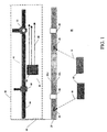
- Fig. 1 illustrates a cross-sectional view of a portion of a ceiling tile system in which the present invention can be utilized.
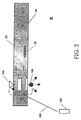
- Fig. 2 illustrates a cross-sectional view of a ceiling tile with an embedded object and an embedded indicator device.
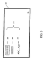
- Fig. 3 illustrates a plan view of a lower surface of a ceiling tile having indicia representative of an object embedded within, or located above, the ceiling tile.
- Fig. 4 illustrates a cross-sectional view of a ceiling tile with indicia located on its lower surface.
- Fig. 5 illustrates a plan view of a lower surface of a ceiling tile system having a mapping of the over-lying building infrastructure.
- the present invention is a method and apparatus for identifying ceiling panels that contain active and/or passive components of an embedded device, or that hide certain key components of a building's infrastructure from an observer positioned in the room below the ceiling tile.
- a side schematic view of a portion of a ceiling tile system 20 is shown having an upper surface 20U and a lower surface 20L and comprising a plurality of individual ceiling tiles 22, five of which are depicted as ceiling tiles 22A-22E. Each ceiling tile has an upper surface 23 and a lower surface 24 as illustrated in Fig. 2.
- Ceiling tile system 20 is suspended from a fixed ceiling (not shown) by suspension members 30, only one of which is depicted in Fig. 1.
- Ceiling tiles 22A and 22D have an embedded object 26 installed therein.
- light sources 28 which emit light having a wavelength range (i.e., spectral bandwidth) that is dependent on the nature of the light source, e.g., incandescent, fluorescent, halogen, etc.
- a room interior 36 Adjacent to the lower surface 20L of the ceiling tile system 20 is a room interior 36, which may be an office having electronic devices 40, such as computers that are part of a local area network (LAN).
- the room interior 36 is illuminated by the ceiling light sources 28.
- building infrastructure 50 Adjacent to the upper surface 20U of ceiling tile system 20 is building infrastructure 50 including, by way of example, a plumbing system 60, having pipes 64, valve 68, pump 72, and an electrical system 80 including circuit breaker unit 86 and wiring 90 leading to a variety of electrical devices (not shown).
- an object 26 is embedded within ceiling tiles 22A and 22D.
- the object 26 can be an electronic communication device such as a "wireless" communication bus or a transmitter/receiver that receives wireless signals 10 from electronic devices 40 and transmits information based on the received wireless signals 10 to a central processing unit (not shown) with which the device is in electronic communication.
- a central processing unit not shown
- Fig. 2 shows a cross-sectional view of a ceiling tile 22 with an embedded indicator device 100.
- the indicator device 100 includes a signal output device 106, a memory chip 110 electrically connected to the signal output device 106, a micro-capacitor 120 electrically connected to the memory chip 110, and an antenna 130 electrically connected to the micro-capacitor 120.
- the micro-capacitor must be of sufficient size to power the signal output device.
- Alternative sources of power include a miniature battery electrically connected to the antenna and signal output device.
- the signal output device can also be powered by a power source located in the plenum.
- the indicator device 100 can be a radio frequency (RFID) tag.
- the signal output device 106 can be a light emitting diode (LED) or a sound generator.
- the signal output device 106 is an LED, it preferably is located at or extends below the lower surface 24 of ceiling tile 22 so that its output is visible to an observer in room interior 36.
- Memory chip 110 contains information about the embedded object 26, including its make and model number, its operating parameters, and its location in the ceiling tile 22. Memory chip 110 also contains information about the type of query signal received by the antenna 130 to which the indicator device 100 should respond.
- RFID technology is based on bi-directional radio frequency communication between a microprocessor-based control system equipped with a read/write unit, and an RFID tag (transponder) attached to an object.
- the tag includes an antenna, control circuitry, and memory in which ID information is stored.
- the memory can be read only or it can be read/write. If it is read only, then the stored information cannot be altered by the user. If it is read/write, the stored information can be overwritten or added to memory at a later date by the user.
- the read/write unit includes an antenna and modulation/demodulation circuits controlled by the microprocessor. In operation, the unit emits an electromagnetic field which extends over a certain volume from the unit. If an RFID tag passes into this volume, the field activates the control circuitry of the tag. The tag identifies itself by transmitting radio frequency waves back to the control unit.
- RF radio frequency
- the system is capable of distinguishing at least two embedded devices in a ceiling tile, the system including at least two indicator devices within a ceiling tile, with each device responsive to query signals of a different frequency from a scanner, the indicator devices providing information in the form of an audio or visual output signal for each one of the embedded objects.
- light-responsive indicia are added to the ceiling tile to identify and provide detailed information concerning an object embedded therein or located above a ceiling tile without moving the ceiling tile.
- the lower surface 24 includes indicia 210 that is preferably at least one of a bar code 220, coded dots or symbols 230, or alphanumeric characters 240.
- Indicia 210 represent in symbolic form the presence or absence of an embedded device 26 or information pertaining thereto.
- Indicia 210 may also be representative of the above-lying building infrastructure 50.
- Indicia 210 are preferably formed from a material that is responsive (e.g., fluorescent) to light of a wavelength other than that emitted by ambient light sources 28. This is because it is preferred that indicia 210 remain hidden in the background of lower surface 24 of ceiling tile 22 during normal illumination of the room interior 36.
- An exemplary material for indicia 210 is a fluorescent paint responsive to ultraviolet (UV) light.
- the indicia 210 can be very simple, such as a large dot.
- a great deal of information about device 26 can be included in bar code indicia, such as the make and model number of the device, and its operating parameters.
- Fig. 4 shows a cross-sectional view of a ceiling tile with indicia 210 positioned on the lower surface 24.
- the following acts are performed to locate and identify an embedded or hidden device using light-responsive indicia:
- Indicia 210 can be sized to be viewed from a distance, or can be sized so that it needs to be viewed through a magnifying device.
- An advantage of having large-sized indicia 210 is that it can be viewed easily by an observer 170 standing in the room interior 36 from a distance of several feet or more. If indicia 210 is sized to be very small, then a large amount of alphanumeric or bar-coded information pertaining to device 26 and/or the over-lying building infrastructure 50 can be provided.
- large indicia comprising symbols for the various components of the infrastructure may be used on the ceiling tile.
- a picture of a valve can be used for representing a valve 68; a picture of a pump for representing a pump 72, and picture of a pipe section for representing pipes 64.
- Fig. 5 represents a plan view of lower surface 20L of ceiling tile system 20 (i.e., looking up at the ceiling from room interior 36) mapping the entire building infrastructure 50 over-lying the ceiling onto lower surface 20L in another embodiment of the present invention.
- This can be done by projecting computer aided drawings (CAD) of the building infrastructure 50 that is above the plane of ceiling tile system 20 and then imprinting or painting a map 200 onto the lower surface 20L in the manner that indicia 210 is applied to each ceiling tile 22.
- CAD computer aided drawings
- indicia 210 pertaining to embedded device 26 located within ceiling tile 22 the process of forming the indicia can be done when the tile is formed, or after manufacture.
- the process for forming the indicia is preferably carried out once the building infrastructure is in place and ceiling tile system 20 is in place.
- indicia 210 pertaining to building infrastructure 50 including forming the aforementioned map of the entire infrastructure on lower surface 20L) once the building infrastructure is known, and once the ceiling tile system is laid out on paper or in a computer database.
- the device identification and location system can as easily be installed in a room wall by embedding the RFID identification and location system in wall panels or by attachment to an exterior surface of the wall.
- the light-responsive indicia can also be affixed to an interior surface of a wall structure. Accordingly, the appended claims are not limited to use with a ceiling tile system and the person of skill in the art will be able to readily apply the concepts herein and make further modifications to the embodiments disclosed. Such modifications are within the scope of the present invention.
Landscapes
- Physics & Mathematics (AREA)
- Life Sciences & Earth Sciences (AREA)
- General Life Sciences & Earth Sciences (AREA)
- General Physics & Mathematics (AREA)
- Geophysics (AREA)
- Illuminated Signs And Luminous Advertising (AREA)
- Burglar Alarm Systems (AREA)
- Radar Systems Or Details Thereof (AREA)
- Geophysics And Detection Of Objects (AREA)
Abstract
Description
A
The
The
If the
An
The
The
However, in one embodiment, a UV light or a so-called "black light" can be used in combination with phosphorescent paint so that the indicia "glows in the dark." In this case, lights 28 may need to be turned off to optimally view the
Claims (37)
- A system for determining the identity and the location of an object hidden by a panel, comprising:a transmitter/receiver device embedded in the panel that stores identifying information for the object; anda scanner for emitting a query signal at a frequency intended to activate a response from the embedded transmitter/receiver device when interrogated by the query signal.
- The system for determining the identity and location of an object of claim 1 wherein the object is embedded in the panel.
- The system for determining the identity and location of an object of claim 1 wherein the transmitter/receiver device comprises a radio frequency identification (RFID) transponder.
- The system for determining the identity and location of an object of claim 1 wherein the transmitter/receiver device comprises an infrared transponder.
- The system for determining the identity and location of an object of claim 3 wherein the RFID transponder memory stores information that includes the object's operating parameters.
- The system for determining the identity and location of an object of claim 3 further comprising a signal output device coupled to the RFID transponder to emit a detectable signal when powered by the RFID transponder, the signal output device being selected from any one of a light emitting diode, a sound generator, and both a light emitting diode and a sound generator.
- The system for determining the identity and location of an object of claim 1 wherein the panel is a ceiling tile.
- The system for determining the identity and location of an object of claim 1 wherein the scanner is a programmed multiple frequency scanner that generates the query signal at a specific frequency according to the type of object being located.
- The system for determining the identity and location of an object of claim 2 wherein the embedded object is selected from any one of a transmitter/receiver that communicates wirelessly with at least one electronic device located in a room interior, a communication bus, and an antenna.
- The system for determining the identity and location of an object of claim 1 wherein the scanner is a portable, hand-held unit.
- A method for identifying and determining the location of an object hidden by a panel, comprising the acts ofstoring identifying information for the object in a memory of a transmitter/receiver device embedded in the panel;emitting a query signal by a scanner device to interrogate the embedded transmitter/receiver device at a frequency intended to activate a response;comparing the query signal to the object identifying information stored in the memory; andgenerating a detectable output signal if the query signal matches the object identifying information stored in the memory.
- The method for identifying and determining the location of an object of claim 11 further comprising receiving an identification and location of the object by an observer in a room interior.
- The method for identifying and determining the location of an object of claim 11 wherein the transmitter/receiver device is selected from any one of a radio frequency identification (RFID) transponder, and an infrared (IR) transponder.
- The method for identifying and determining the location of an object of claim 11 further comprising storing information that identifies the location of the object in the memory.
- The method for identifying and determining the location of an object of claim 11 further comprising storing information that specifies the operating parameters of the object in memory.
- The method for identifying and determining the location of an object of claim 11 further comprising activating a signal generator selected from any one of a light emitting diode to generate a visible detectable output signal, and a sound system to generate an audible detectable output signal.
- The method for identifying and determining the location of an object of claim 11 further comprising generating a query signal at a specific frequency according to the type of object being located.
- A system for determining the identity and location of an object hidden by a panel, comprising:an indicia affixed to a first surface of the panel, the indicia containing information identifying the object; andan illumination device for irradiating the first surface of the ceiling tile with a light wave.
- The system for determining the identity and location of an object of claim 18 wherein the object is embedded in the panel.
- The system for determining the identity and location of an object of claim 18 wherein the object is hidden behind the panel.
- The system for determining the identity and location of an object of claim 18 wherein the irradiating light wave has a wavelength outside the visible spectrum.
- The system for determining the identity and location of an object of claim 18 wherein the indicia is selected from any one of a bar code identifying the object and readable by a scanner, coded dots, pictorial symbols, and alphanumeric characters.
- The system for determining the identity and location of an object of claim 18 wherein the indicia is a phosphorescent paint.
- The system for determining the identity and location of an object of claim 18 wherein the indicia responds to radiation by radiating a light wave to make the indicia visible to an observer.
- The system for determining the identity and location of an object of claim 24 wherein the indicia is viewable through a device selected from any one of a filter, an infrared viewer, and an ultraviolet viewing instrument.
- The system for determining the identity and location of an object of claim 18 wherein the panel is a ceiling tile.
- The system for determining the identity and location of an object of claim 19 wherein the embedded object is selected from a group including a transmitter/receiver that communicates wirelessly with at least one electronic device located in a room interior, a communication bus, and an antenna.
- The system for determining the identity and location of an object of claim 20 wherein the object is part of the building infrastructure.
- The system for determining the identity and location of an object of claim 28 wherein the object is selected from a group including a plumbing fixture, an electrical fixture, and a component of a heating, ventilating and air conditioning (HVAC) ductwork.
- A method for identifying and determining the location of an object hidden by a panel, comprising the acts of:affixing identifying information for the object on a first surface of the panel;irradiating the first surface with a light wave from an illumination device; andin response to the irradiation from the illumination device, radiating a light wave from the indicia to make the indicia visible to an observer.
- The method for identifying and determining the location of an object of claim 30 wherein the object is embedded in the panel.
- The method for identifying and determining the location of an object of claim 30 wherein the object is behind the panel.
- The method for identifying and determining the location of an object of claim 30 wherein the light wave has a wavelength outside the visible spectrum.
- The method for identifying and determining the location of an object of claim 30 further comprising receiving an identification and location of the embedded object by an observer.
- The method for identifying and determining the location of an object of claim 30 wherein the indicia is selected from the group consisting of a bar code identifying the object, code dots, pictorial symbols, and alphanumeric characters.
- The method for identifying and determining the location of an object of claim 30 further comprising the act of affixing the indicia by applying a phosphorescent paint to the first surface.
- The method for identifying and determining the location of an object of claim 30 further comprising viewing the irradiated indicia through a device selected from a group including a filter, an infrared viewer and an ultraviolet viewing instrument.
Applications Claiming Priority (2)
| Application Number | Priority Date | Filing Date | Title |
|---|---|---|---|
| US619081 | 2000-07-17 | ||
| US09/619,081 US6693512B1 (en) | 2000-07-17 | 2000-07-17 | Device location and identification system |
Publications (3)
| Publication Number | Publication Date |
|---|---|
| EP1174834A2 true EP1174834A2 (en) | 2002-01-23 |
| EP1174834A3 EP1174834A3 (en) | 2005-06-22 |
| EP1174834B1 EP1174834B1 (en) | 2009-12-16 |
Family
ID=24480378
Family Applications (1)
| Application Number | Title | Priority Date | Filing Date |
|---|---|---|---|
| EP01116864A Expired - Lifetime EP1174834B1 (en) | 2000-07-17 | 2001-07-10 | Device location and identification system |
Country Status (8)
| Country | Link |
|---|---|
| US (1) | US6693512B1 (en) |
| EP (1) | EP1174834B1 (en) |
| JP (1) | JP2002131443A (en) |
| AT (1) | ATE452396T1 (en) |
| AU (1) | AU5430101A (en) |
| CA (1) | CA2352427A1 (en) |
| DE (1) | DE60140781D1 (en) |
| MX (1) | MXPA01007202A (en) |
Cited By (6)
| Publication number | Priority date | Publication date | Assignee | Title |
|---|---|---|---|---|
| US7605702B2 (en) | 2004-06-25 | 2009-10-20 | Nec Corporation | Article position management system, article position management method, terminal device, server, and article position management program |
| EP2424121A4 (en) * | 2009-03-27 | 2012-09-19 | Idro Co Ltd | REPEATER TYPE RFID COMMUNICATION SYSTEM |
| US8674616B2 (en) | 2008-10-10 | 2014-03-18 | Qualcomm Mems Technologies, Inc. | Distributed illumination system |
| CN104075750A (en) * | 2014-07-02 | 2014-10-01 | 北京机械设备研究所 | Measuring method for gas or liquid |
| US8924395B2 (en) | 2010-10-06 | 2014-12-30 | Planet Data Solutions | System and method for indexing electronic discovery data |
| CN106601013A (en) * | 2016-11-30 | 2017-04-26 | 武汉长江通信智联技术有限公司 | Automatic station reporting method of bus |
Families Citing this family (31)
| Publication number | Priority date | Publication date | Assignee | Title |
|---|---|---|---|---|
| US7887146B1 (en) | 2001-08-18 | 2011-02-15 | Gsl Solutions, Inc. | Suspended storage system for pharmacy |
| US6621417B2 (en) * | 2001-08-09 | 2003-09-16 | Edgar Alan Duncan | Passive RFID transponder/reader system and method for hidden obstacle detection and avoidance |
| US20050184857A1 (en) * | 2003-12-11 | 2005-08-25 | Triteq Lock And Security, Llc | Electronic security apparatus and method for monitoring mechanical keys and other items |
| US20110276609A1 (en) | 2001-12-27 | 2011-11-10 | Denison William D | Method for Controlling and Recording the Security of an Enclosure |
| US7007698B2 (en) * | 2002-04-03 | 2006-03-07 | Boston Scientific Corporation | Body lumen closure |
| JP4623971B2 (en) * | 2002-04-11 | 2011-02-02 | センサーマチック・エレクトロニックス・コーポレーション | Portable combination electronic article surveillance system and system and method for managing assets using barcode scanner |
| ITMI20021685A1 (en) * | 2002-07-29 | 2004-01-29 | Microhard Srl | DEVICE SUITABLE TO DETECT THE PRESENCE OF A RESONANT CIRCUIT OF A TRASPONDER IN THE ENVIRONMENT OF THE DEVICE ITSELF AND WITHOUT CONTACTS |
| US8175799B1 (en) * | 2002-10-15 | 2012-05-08 | Douglas Edward Woehler | Location system |
| US20040252488A1 (en) * | 2003-04-01 | 2004-12-16 | Innovalight | Light-emitting ceiling tile |
| US9198786B2 (en) * | 2003-09-03 | 2015-12-01 | Bolton Medical, Inc. | Lumen repair device with capture structure |
| US7750352B2 (en) * | 2004-08-10 | 2010-07-06 | Pinion Technologies, Inc. | Light strips for lighting and backlighting applications |
| CN1741028A (en) * | 2004-08-25 | 2006-03-01 | 国际商业机器公司 | Article position detecting equipment and method |
| US20060232412A1 (en) * | 2005-04-15 | 2006-10-19 | Jorge Tabacman & Associates P/L | Intelligent reader system and method for identifying and tracking goods and materials transported in pallets, including but not limited to scaffolding materials |
| US7423523B2 (en) * | 2005-08-03 | 2008-09-09 | The Boeing Company | Composite ply layup using electronically identifiable tags |
| US7561786B1 (en) * | 2005-12-09 | 2009-07-14 | Qurio Holdings, Inc | Methods and systems for automatic identification of device accessories, and devices configured to automatically identify attached accessories |
| US20110254661A1 (en) | 2005-12-23 | 2011-10-20 | Invue Security Products Inc. | Programmable security system and method for protecting merchandise |
| CN101657799B (en) * | 2008-03-31 | 2013-03-27 | Nec显示器解决方案株式会社 | Terminal, network device, network device retrieval system consisting of terminal and network device and network device retrieval method |
| US12046342B2 (en) | 2011-02-14 | 2024-07-23 | Gsl Solutions, Inc. | Pharmacy stock supply tracking system |
| US11244747B2 (en) | 2014-10-16 | 2022-02-08 | Gsl Solutions, Inc. | Pharmacy security system |
| US10402927B2 (en) | 2011-12-30 | 2019-09-03 | Elwha Llc | Evidence-based healthcare information management protocols |
| US10340034B2 (en) | 2011-12-30 | 2019-07-02 | Elwha Llc | Evidence-based healthcare information management protocols |
| US10475142B2 (en) | 2011-12-30 | 2019-11-12 | Elwha Llc | Evidence-based healthcare information management protocols |
| US10528913B2 (en) | 2011-12-30 | 2020-01-07 | Elwha Llc | Evidence-based healthcare information management protocols |
| US10552581B2 (en) | 2011-12-30 | 2020-02-04 | Elwha Llc | Evidence-based healthcare information management protocols |
| US10559380B2 (en) | 2011-12-30 | 2020-02-11 | Elwha Llc | Evidence-based healthcare information management protocols |
| US10679309B2 (en) | 2011-12-30 | 2020-06-09 | Elwha Llc | Evidence-based healthcare information management protocols |
| US10028362B2 (en) | 2014-11-07 | 2018-07-17 | Steven G. Mlodzik | Locator lights |
| BR112017013997B1 (en) | 2014-12-29 | 2022-06-28 | Invue Security Products Inc | MERCHANDISE SECURITY SYSTEM AND METHOD FOR PROTECTING AN THEFT-SUSCEPTIBLE MERCHANDISE |
| WO2017181137A1 (en) | 2016-04-15 | 2017-10-19 | Mobile Tech, Inc. | Authorization control for an anti-theft security system |
| US10908312B2 (en) | 2016-06-24 | 2021-02-02 | Stanley Black & Decker Inc. | Systems and methods for locating a metal object |
| CN108363932B (en) | 2017-01-26 | 2023-04-18 | 手持产品公司 | Method for reading bar code and deactivating electronic anti-theft label of commodity |
Family Cites Families (22)
| Publication number | Priority date | Publication date | Assignee | Title |
|---|---|---|---|---|
| US2854840A (en) * | 1956-09-28 | 1958-10-07 | Aaron W Anderson | Magnetic marker wire |
| AT374596B (en) * | 1979-04-20 | 1984-05-10 | Enander Bengt | TO FIND AVALANCHE VICTIMS, ANSWERS TO BE WEARED ON THE BODY |
| US4656463A (en) * | 1983-04-21 | 1987-04-07 | Intelli-Tech Corporation | LIMIS systems, devices and methods |
| US4724309A (en) * | 1984-04-09 | 1988-02-09 | Greene Edwin B | Machine readable document and method for processing |
| US4740257A (en) | 1985-03-04 | 1988-04-26 | Acoustic Industries, Inc. | Ceiling tile covering system |
| US4725078A (en) * | 1986-06-30 | 1988-02-16 | National Gypsum Company | Wallboard identification system |
| GB8915853D0 (en) * | 1989-07-11 | 1989-08-31 | Du Pont Uk | Identification of hidden pipes etc |
| US5116654A (en) * | 1989-09-18 | 1992-05-26 | Minnesota Mining And Manufacturing Company | Self-dispensing spaced electronic markers |
| US5756981A (en) * | 1992-02-27 | 1998-05-26 | Symbol Technologies, Inc. | Optical scanner for reading and decoding one- and-two-dimensional symbologies at variable depths of field including memory efficient high speed image processing means and high accuracy image analysis means |
| GB2289602B (en) * | 1994-05-12 | 1998-02-11 | Roke Manor Research | Improvements in or relating to detection systems |
| US5942987A (en) * | 1994-09-09 | 1999-08-24 | Intermec Ip Corp. | Radio frequency identification system with write broadcast capability |
| US5523750A (en) * | 1994-09-30 | 1996-06-04 | Palomar Technologies Corporation | Transponder system for communicating through an RF barrier |
| JP3055772B2 (en) * | 1997-04-04 | 2000-06-26 | 株式会社関電工 | Method and apparatus for exploring underground objects |
| US6249227B1 (en) * | 1998-01-05 | 2001-06-19 | Intermec Ip Corp. | RFID integrated in electronic assets |
| US6206282B1 (en) * | 1998-03-03 | 2001-03-27 | Pyper Products Corporation | RF embedded identification device |
| US6076859A (en) * | 1998-06-01 | 2000-06-20 | Express Systems Incorporated | Method and label system for marking property |
| EP1862981B1 (en) * | 1998-08-14 | 2014-12-31 | 3M Innovative Properties Company | Applications for radio frequency identification systems |
| US6133738A (en) * | 1998-10-02 | 2000-10-17 | Minarovic; Joe T. | Detectable transponder reel housing |
| US6133832A (en) * | 1998-10-22 | 2000-10-17 | Winder; Jeffrey S. | Article location system |
| US6097293A (en) * | 1999-04-15 | 2000-08-01 | Industrial Technology, Inc. | Passive electrical marker for underground use and method of making thereof |
| US6542083B1 (en) * | 1999-11-23 | 2003-04-01 | Xerox Corporation | Electronic tag position detection using radio broadcast |
| CA2311834C (en) * | 2000-06-16 | 2002-09-24 | Norscan Instruments Ltd. | An interactive method and apparatus for locating and identifying utilities |
-
2000
- 2000-07-17 US US09/619,081 patent/US6693512B1/en not_active Expired - Fee Related
-
2001
- 2001-07-05 CA CA002352427A patent/CA2352427A1/en not_active Abandoned
- 2001-07-10 AU AU54301/01A patent/AU5430101A/en not_active Abandoned
- 2001-07-10 AT AT01116864T patent/ATE452396T1/en not_active IP Right Cessation
- 2001-07-10 DE DE60140781T patent/DE60140781D1/en not_active Expired - Lifetime
- 2001-07-10 EP EP01116864A patent/EP1174834B1/en not_active Expired - Lifetime
- 2001-07-12 JP JP2001212886A patent/JP2002131443A/en not_active Withdrawn
- 2001-07-16 MX MXPA01007202A patent/MXPA01007202A/en unknown
Cited By (6)
| Publication number | Priority date | Publication date | Assignee | Title |
|---|---|---|---|---|
| US7605702B2 (en) | 2004-06-25 | 2009-10-20 | Nec Corporation | Article position management system, article position management method, terminal device, server, and article position management program |
| US8674616B2 (en) | 2008-10-10 | 2014-03-18 | Qualcomm Mems Technologies, Inc. | Distributed illumination system |
| EP2424121A4 (en) * | 2009-03-27 | 2012-09-19 | Idro Co Ltd | REPEATER TYPE RFID COMMUNICATION SYSTEM |
| US8924395B2 (en) | 2010-10-06 | 2014-12-30 | Planet Data Solutions | System and method for indexing electronic discovery data |
| CN104075750A (en) * | 2014-07-02 | 2014-10-01 | 北京机械设备研究所 | Measuring method for gas or liquid |
| CN106601013A (en) * | 2016-11-30 | 2017-04-26 | 武汉长江通信智联技术有限公司 | Automatic station reporting method of bus |
Also Published As
| Publication number | Publication date |
|---|---|
| ATE452396T1 (en) | 2010-01-15 |
| US6693512B1 (en) | 2004-02-17 |
| DE60140781D1 (en) | 2010-01-28 |
| JP2002131443A (en) | 2002-05-09 |
| EP1174834B1 (en) | 2009-12-16 |
| MXPA01007202A (en) | 2004-10-29 |
| EP1174834A3 (en) | 2005-06-22 |
| CA2352427A1 (en) | 2002-01-17 |
| AU5430101A (en) | 2002-01-24 |
Similar Documents
| Publication | Publication Date | Title |
|---|---|---|
| US6693512B1 (en) | Device location and identification system | |
| US7511613B2 (en) | Lighting control with occupancy detection | |
| US9413457B2 (en) | LED light communication system | |
| US10050705B2 (en) | LED light interior room and building communication system | |
| US8217763B2 (en) | Lighting device for floors | |
| US20060062582A1 (en) | Device, system and method for providing visible light information, visible light information reader, program thereof, and computer-readable information storage medium for storing program | |
| JP6247669B2 (en) | LED lamp for beacon built-in illumination, beacon system using the same, and beacon control method | |
| JP2014506328A (en) | Position estimation of electronic equipment | |
| US10982875B2 (en) | RF antenna positioning techniques | |
| US6163278A (en) | Electronic locating system for locating vehicles at assembly plants | |
| JP6399174B2 (en) | Lighting apparatus and communication method | |
| JP2005061934A (en) | Position information management system using led lighting system | |
| JP6627940B2 (en) | Position management system and position management method | |
| JP2009035363A (en) | Article position management system |
Legal Events
| Date | Code | Title | Description |
|---|---|---|---|
| PUAI | Public reference made under article 153(3) epc to a published international application that has entered the european phase |
Free format text: ORIGINAL CODE: 0009012 |
|
| AK | Designated contracting states |
Kind code of ref document: A2 Designated state(s): AT BE CH CY DE DK ES FI FR GB GR IE IT LI LU MC NL PT SE TR |
|
| AX | Request for extension of the european patent |
Free format text: AL;LT;LV;MK;RO;SI |
|
| PUAL | Search report despatched |
Free format text: ORIGINAL CODE: 0009013 |
|
| AK | Designated contracting states |
Kind code of ref document: A3 Designated state(s): AT BE CH CY DE DK ES FI FR GB GR IE IT LI LU MC NL PT SE TR |
|
| AX | Request for extension of the european patent |
Extension state: AL LT LV MK RO SI |
|
| RIC1 | Information provided on ipc code assigned before grant |
Ipc: 7G 08B 29/00 A |
|
| 17P | Request for examination filed |
Effective date: 20051209 |
|
| AKX | Designation fees paid |
Designated state(s): AT BE CH CY DE DK ES FI FR GB GR IE IT LI LU MC NL PT SE TR |
|
| 17Q | First examination report despatched |
Effective date: 20051228 |
|
| GRAP | Despatch of communication of intention to grant a patent |
Free format text: ORIGINAL CODE: EPIDOSNIGR1 |
|
| GRAS | Grant fee paid |
Free format text: ORIGINAL CODE: EPIDOSNIGR3 |
|
| GRAA | (expected) grant |
Free format text: ORIGINAL CODE: 0009210 |
|
| AK | Designated contracting states |
Kind code of ref document: B1 Designated state(s): AT BE CH CY DE DK ES FI FR GB GR IE IT LI LU MC NL PT SE TR |
|
| REG | Reference to a national code |
Ref country code: GB Ref legal event code: FG4D |
|
| REG | Reference to a national code |
Ref country code: CH Ref legal event code: EP |
|
| REG | Reference to a national code |
Ref country code: IE Ref legal event code: FG4D |
|
| REF | Corresponds to: |
Ref document number: 60140781 Country of ref document: DE Date of ref document: 20100128 Kind code of ref document: P |
|
| REG | Reference to a national code |
Ref country code: NL Ref legal event code: T3 |
|
| PG25 | Lapsed in a contracting state [announced via postgrant information from national office to epo] |
Ref country code: SE Free format text: LAPSE BECAUSE OF FAILURE TO SUBMIT A TRANSLATION OF THE DESCRIPTION OR TO PAY THE FEE WITHIN THE PRESCRIBED TIME-LIMIT Effective date: 20091216 Ref country code: FI Free format text: LAPSE BECAUSE OF FAILURE TO SUBMIT A TRANSLATION OF THE DESCRIPTION OR TO PAY THE FEE WITHIN THE PRESCRIBED TIME-LIMIT Effective date: 20091216 |
|
| PG25 | Lapsed in a contracting state [announced via postgrant information from national office to epo] |
Ref country code: AT Free format text: LAPSE BECAUSE OF FAILURE TO SUBMIT A TRANSLATION OF THE DESCRIPTION OR TO PAY THE FEE WITHIN THE PRESCRIBED TIME-LIMIT Effective date: 20091216 |
|
| PG25 | Lapsed in a contracting state [announced via postgrant information from national office to epo] |
Ref country code: PT Free format text: LAPSE BECAUSE OF FAILURE TO SUBMIT A TRANSLATION OF THE DESCRIPTION OR TO PAY THE FEE WITHIN THE PRESCRIBED TIME-LIMIT Effective date: 20100416 Ref country code: ES Free format text: LAPSE BECAUSE OF FAILURE TO SUBMIT A TRANSLATION OF THE DESCRIPTION OR TO PAY THE FEE WITHIN THE PRESCRIBED TIME-LIMIT Effective date: 20100327 |
|
| PG25 | Lapsed in a contracting state [announced via postgrant information from national office to epo] |
Ref country code: BE Free format text: LAPSE BECAUSE OF FAILURE TO SUBMIT A TRANSLATION OF THE DESCRIPTION OR TO PAY THE FEE WITHIN THE PRESCRIBED TIME-LIMIT Effective date: 20091216 |
|
| PLBE | No opposition filed within time limit |
Free format text: ORIGINAL CODE: 0009261 |
|
| STAA | Information on the status of an ep patent application or granted ep patent |
Free format text: STATUS: NO OPPOSITION FILED WITHIN TIME LIMIT |
|
| PG25 | Lapsed in a contracting state [announced via postgrant information from national office to epo] |
Ref country code: GR Free format text: LAPSE BECAUSE OF FAILURE TO SUBMIT A TRANSLATION OF THE DESCRIPTION OR TO PAY THE FEE WITHIN THE PRESCRIBED TIME-LIMIT Effective date: 20100317 Ref country code: CY Free format text: LAPSE BECAUSE OF FAILURE TO SUBMIT A TRANSLATION OF THE DESCRIPTION OR TO PAY THE FEE WITHIN THE PRESCRIBED TIME-LIMIT Effective date: 20091216 |
|
| 26N | No opposition filed |
Effective date: 20100917 |
|
| PG25 | Lapsed in a contracting state [announced via postgrant information from national office to epo] |
Ref country code: DK Free format text: LAPSE BECAUSE OF FAILURE TO SUBMIT A TRANSLATION OF THE DESCRIPTION OR TO PAY THE FEE WITHIN THE PRESCRIBED TIME-LIMIT Effective date: 20091216 |
|
| PG25 | Lapsed in a contracting state [announced via postgrant information from national office to epo] |
Ref country code: MC Free format text: LAPSE BECAUSE OF NON-PAYMENT OF DUE FEES Effective date: 20100731 |
|
| REG | Reference to a national code |
Ref country code: CH Ref legal event code: PL |
|
| PG25 | Lapsed in a contracting state [announced via postgrant information from national office to epo] |
Ref country code: IT Free format text: LAPSE BECAUSE OF FAILURE TO SUBMIT A TRANSLATION OF THE DESCRIPTION OR TO PAY THE FEE WITHIN THE PRESCRIBED TIME-LIMIT Effective date: 20091216 |
|
| PG25 | Lapsed in a contracting state [announced via postgrant information from national office to epo] |
Ref country code: CH Free format text: LAPSE BECAUSE OF NON-PAYMENT OF DUE FEES Effective date: 20100731 Ref country code: LI Free format text: LAPSE BECAUSE OF NON-PAYMENT OF DUE FEES Effective date: 20100731 |
|
| PG25 | Lapsed in a contracting state [announced via postgrant information from national office to epo] |
Ref country code: IE Free format text: LAPSE BECAUSE OF NON-PAYMENT OF DUE FEES Effective date: 20100710 |
|
| PGFP | Annual fee paid to national office [announced via postgrant information from national office to epo] |
Ref country code: DE Payment date: 20110830 Year of fee payment: 11 Ref country code: FR Payment date: 20110830 Year of fee payment: 11 Ref country code: GB Payment date: 20110825 Year of fee payment: 11 |
|
| PGFP | Annual fee paid to national office [announced via postgrant information from national office to epo] |
Ref country code: NL Payment date: 20110901 Year of fee payment: 11 |
|
| PG25 | Lapsed in a contracting state [announced via postgrant information from national office to epo] |
Ref country code: LU Free format text: LAPSE BECAUSE OF NON-PAYMENT OF DUE FEES Effective date: 20100710 |
|
| PG25 | Lapsed in a contracting state [announced via postgrant information from national office to epo] |
Ref country code: TR Free format text: LAPSE BECAUSE OF FAILURE TO SUBMIT A TRANSLATION OF THE DESCRIPTION OR TO PAY THE FEE WITHIN THE PRESCRIBED TIME-LIMIT Effective date: 20091216 |
|
| REG | Reference to a national code |
Ref country code: NL Ref legal event code: V1 Effective date: 20130201 |
|
| GBPC | Gb: european patent ceased through non-payment of renewal fee |
Effective date: 20120710 |
|
| REG | Reference to a national code |
Ref country code: FR Ref legal event code: ST Effective date: 20130329 |
|
| PG25 | Lapsed in a contracting state [announced via postgrant information from national office to epo] |
Ref country code: GB Free format text: LAPSE BECAUSE OF NON-PAYMENT OF DUE FEES Effective date: 20120710 Ref country code: DE Free format text: LAPSE BECAUSE OF NON-PAYMENT OF DUE FEES Effective date: 20130201 Ref country code: NL Free format text: LAPSE BECAUSE OF NON-PAYMENT OF DUE FEES Effective date: 20130201 Ref country code: FR Free format text: LAPSE BECAUSE OF NON-PAYMENT OF DUE FEES Effective date: 20120731 |
|
| REG | Reference to a national code |
Ref country code: DE Ref legal event code: R119 Ref document number: 60140781 Country of ref document: DE Effective date: 20130201 |