EP1174601A2 - Monitoring of diesel emissions control system - Google Patents
Monitoring of diesel emissions control system Download PDFInfo
- Publication number
- EP1174601A2 EP1174601A2 EP01305776A EP01305776A EP1174601A2 EP 1174601 A2 EP1174601 A2 EP 1174601A2 EP 01305776 A EP01305776 A EP 01305776A EP 01305776 A EP01305776 A EP 01305776A EP 1174601 A2 EP1174601 A2 EP 1174601A2
- Authority
- EP
- European Patent Office
- Prior art keywords
- temperature
- catalyst
- light
- fuel injection
- nlt
- Prior art date
- Legal status (The legal status is an assumption and is not a legal conclusion. Google has not performed a legal analysis and makes no representation as to the accuracy of the status listed.)
- Withdrawn
Links
Images


Classifications
-
- F—MECHANICAL ENGINEERING; LIGHTING; HEATING; WEAPONS; BLASTING
- F01—MACHINES OR ENGINES IN GENERAL; ENGINE PLANTS IN GENERAL; STEAM ENGINES
- F01N—GAS-FLOW SILENCERS OR EXHAUST APPARATUS FOR MACHINES OR ENGINES IN GENERAL; GAS-FLOW SILENCERS OR EXHAUST APPARATUS FOR INTERNAL-COMBUSTION ENGINES
- F01N11/00—Monitoring or diagnostic devices for exhaust-gas treatment apparatus
- F01N11/002—Monitoring or diagnostic devices for exhaust-gas treatment apparatus the diagnostic devices measuring or estimating temperature or pressure in, or downstream of the exhaust apparatus
-
- F—MECHANICAL ENGINEERING; LIGHTING; HEATING; WEAPONS; BLASTING
- F01—MACHINES OR ENGINES IN GENERAL; ENGINE PLANTS IN GENERAL; STEAM ENGINES
- F01N—GAS-FLOW SILENCERS OR EXHAUST APPARATUS FOR MACHINES OR ENGINES IN GENERAL; GAS-FLOW SILENCERS OR EXHAUST APPARATUS FOR INTERNAL-COMBUSTION ENGINES
- F01N3/00—Exhaust or silencing apparatus having means for purifying, rendering innocuous, or otherwise treating exhaust
- F01N3/08—Exhaust or silencing apparatus having means for purifying, rendering innocuous, or otherwise treating exhaust for rendering innocuous
- F01N3/10—Exhaust or silencing apparatus having means for purifying, rendering innocuous, or otherwise treating exhaust for rendering innocuous by thermal or catalytic conversion of noxious components of exhaust
- F01N3/18—Exhaust or silencing apparatus having means for purifying, rendering innocuous, or otherwise treating exhaust for rendering innocuous by thermal or catalytic conversion of noxious components of exhaust characterised by methods of operation; Control
- F01N3/20—Exhaust or silencing apparatus having means for purifying, rendering innocuous, or otherwise treating exhaust for rendering innocuous by thermal or catalytic conversion of noxious components of exhaust characterised by methods of operation; Control specially adapted for catalytic conversion
- F01N3/206—Adding periodically or continuously substances to exhaust gases for promoting purification, e.g. catalytic material in liquid form, NOx reducing agents
- F01N3/2066—Selective catalytic reduction [SCR]
-
- F—MECHANICAL ENGINEERING; LIGHTING; HEATING; WEAPONS; BLASTING
- F01—MACHINES OR ENGINES IN GENERAL; ENGINE PLANTS IN GENERAL; STEAM ENGINES
- F01N—GAS-FLOW SILENCERS OR EXHAUST APPARATUS FOR MACHINES OR ENGINES IN GENERAL; GAS-FLOW SILENCERS OR EXHAUST APPARATUS FOR INTERNAL-COMBUSTION ENGINES
- F01N2550/00—Monitoring or diagnosing the deterioration of exhaust systems
-
- F—MECHANICAL ENGINEERING; LIGHTING; HEATING; WEAPONS; BLASTING
- F01—MACHINES OR ENGINES IN GENERAL; ENGINE PLANTS IN GENERAL; STEAM ENGINES
- F01N—GAS-FLOW SILENCERS OR EXHAUST APPARATUS FOR MACHINES OR ENGINES IN GENERAL; GAS-FLOW SILENCERS OR EXHAUST APPARATUS FOR INTERNAL-COMBUSTION ENGINES
- F01N2550/00—Monitoring or diagnosing the deterioration of exhaust systems
- F01N2550/02—Catalytic activity of catalytic converters
-
- F—MECHANICAL ENGINEERING; LIGHTING; HEATING; WEAPONS; BLASTING
- F01—MACHINES OR ENGINES IN GENERAL; ENGINE PLANTS IN GENERAL; STEAM ENGINES
- F01N—GAS-FLOW SILENCERS OR EXHAUST APPARATUS FOR MACHINES OR ENGINES IN GENERAL; GAS-FLOW SILENCERS OR EXHAUST APPARATUS FOR INTERNAL-COMBUSTION ENGINES
- F01N2610/00—Adding substances to exhaust gases
- F01N2610/03—Adding substances to exhaust gases the substance being hydrocarbons, e.g. engine fuel
-
- Y—GENERAL TAGGING OF NEW TECHNOLOGICAL DEVELOPMENTS; GENERAL TAGGING OF CROSS-SECTIONAL TECHNOLOGIES SPANNING OVER SEVERAL SECTIONS OF THE IPC; TECHNICAL SUBJECTS COVERED BY FORMER USPC CROSS-REFERENCE ART COLLECTIONS [XRACs] AND DIGESTS
- Y02—TECHNOLOGIES OR APPLICATIONS FOR MITIGATION OR ADAPTATION AGAINST CLIMATE CHANGE
- Y02A—TECHNOLOGIES FOR ADAPTATION TO CLIMATE CHANGE
- Y02A50/00—TECHNOLOGIES FOR ADAPTATION TO CLIMATE CHANGE in human health protection, e.g. against extreme weather
- Y02A50/20—Air quality improvement or preservation, e.g. vehicle emission control or emission reduction by using catalytic converters
-
- Y—GENERAL TAGGING OF NEW TECHNOLOGICAL DEVELOPMENTS; GENERAL TAGGING OF CROSS-SECTIONAL TECHNOLOGIES SPANNING OVER SEVERAL SECTIONS OF THE IPC; TECHNICAL SUBJECTS COVERED BY FORMER USPC CROSS-REFERENCE ART COLLECTIONS [XRACs] AND DIGESTS
- Y02—TECHNOLOGIES OR APPLICATIONS FOR MITIGATION OR ADAPTATION AGAINST CLIMATE CHANGE
- Y02T—CLIMATE CHANGE MITIGATION TECHNOLOGIES RELATED TO TRANSPORTATION
- Y02T10/00—Road transport of goods or passengers
- Y02T10/10—Internal combustion engine [ICE] based vehicles
- Y02T10/12—Improving ICE efficiencies
-
- Y—GENERAL TAGGING OF NEW TECHNOLOGICAL DEVELOPMENTS; GENERAL TAGGING OF CROSS-SECTIONAL TECHNOLOGIES SPANNING OVER SEVERAL SECTIONS OF THE IPC; TECHNICAL SUBJECTS COVERED BY FORMER USPC CROSS-REFERENCE ART COLLECTIONS [XRACs] AND DIGESTS
- Y02—TECHNOLOGIES OR APPLICATIONS FOR MITIGATION OR ADAPTATION AGAINST CLIMATE CHANGE
- Y02T—CLIMATE CHANGE MITIGATION TECHNOLOGIES RELATED TO TRANSPORTATION
- Y02T10/00—Road transport of goods or passengers
- Y02T10/10—Internal combustion engine [ICE] based vehicles
- Y02T10/40—Engine management systems
Definitions
- This invention relates to on-board diagnostics and, more particularly, to an on-board diagnostic method and system for diesel vehicles that determines the functionality of a catalyst as well as secondary fuel injection operation.
- the catalyst activity may degrade with time and the reductant delivery system may fail for some reasons.
- two key elements must be monitored continuously as required by OBDII.
- Analysis of the catalyst reveals that as catalyst ages, the light-off temperatures of NO x , HC, and CO increase, and the NO x conversion efficiencies decrease.
- the peak conversion efficiencies for both HC and CO remain approximately the same as shown in the accompanying Figures 1 and 2.
- the catalytic exotherm may remain the same, but the catalyst temperature to produce that exotherm increases.
- the light-off temperature must be determined, in particular, the HC light-off temperature.
- HC light-off temperature a series of exotherm vs. pre-catalyst temperatures (T) needs to be measured during fuel injection and temperature ramp-up excursion.
- This delay time, dt can be determined experimentally for each vehicle to fine-tune a simplified thermal model established. See, for example, "A Simplified Approach to Modeling Exhaust System Emissions: SIMTWC", P. M. Laing, M. D. Shane, S. Son, A. A. Adamczyk and P. Li, SAE, 1999-01-3476.
- a diesel diagnostic method that detects the operation of secondary fuel injection and monitors catalyst activity by monitoring the magnitude of temperature rise and the HC light-off temperature of a catalyst system due to exotherm generated by the after treatment reductant injection.
- an on-board diagnostic method for detection of the functionality of the diesel emissions control system that permits a continuous operational check of the secondary fuel injection system and the catalyst activity. This is accomplished by monitoring the HC light-off temperature and the magnitude of temperature rise, MTR, due to the exotherm generated by the catalysts in an active lean NO x catalyst system. MTR generated by the catalysts is related to the amount of secondary fuel injection, exhaust flow rate, and catalytic conversion of HC. The light-off temperature, LT, is related to the activity of the catalyst. By continuously monitoring these two parameters with reference to theoretical values stored in an engine control computer on the vehicle, the operation of the secondary fuel injection system and catalyst activity can be evaluated. When either of the parameters falls below a predetermined threshold value, the vehicle emissions may exceed emission standards and, if so, the system causes a malfunction indicator light (MIL) to be energised to advise the driver of the need for service.
- MIL malfunction indicator light
- a system for implementing the method of the present invention includes pre-catalyst and post-catalyst thermocouples TC1 and TC2, respectively, that are placed one-half inch from the face of the brick of catalyst 10.
- a MAF sensor 12 measures air flow into the engine 14, and the information from the sensor 12 is used by an electronic engine computer (EEC) 16 to calculate engine exhaust flow. This information plus engine speed and load are used by EEC to control an injector 18 for delivery of a desired amount of hydrocarbon into the catalyst 10.
- EEC electronic engine computer
- MIL malfunction indicator lamp
- a lookup table of the delay times (dt) vs. small increments of flow rate is generated over the entire range of the driving cycle and stored in the EEC 16.
- a typical chart of the data in the lookup table is shown in Figure 4.
- Another lookup table of theoretical temperature rises (TDT) vs. HC concentrations (which are functions of quantity of secondary fuel injection and exhaust flow rates) is stored in the EEC 16.
- a typical chart of this data is shown in Figure 5.
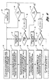
- FIG. 6 a flowchart of the method of the present invention is shown.
- controlled amount of diesel fuel is routinely injected into the exhaust to enhance catalytic reduction of NOX x .
- the EEC determines the rate and the duration of HC injection in the specified temperature range and engine speed and load. This information plus the pre- and post-catalyst temperatures are recorded for a predetermined time period (e.g., 300 to 1200 sec) in the EEC for analysis. After the analysis, the data will be erased for the next batch recording and analysis.
- a predetermined time period e.g. 300 to 1200 sec
- T1 and T2 are the lower and upper limits of a temperature range, which encloses the HC light-off temperature (LT).
- the LT is equal to that of a fresh catalyst, initially, but is to be updated periodically due to catalyst ageing.
- the range of (T2-T1) can be anywhere from 10° to 300° C, preferably from 20° to 120° C.
- T(T) and R(T) are calculated. As indicated in block 24, once the sections are selected, the EEC begins to determine delay time, dt, and the predicted post-catalyst temperature PPT(T) for each T, assuming no fuel injection occurred, from the lookup tables. For the first data point in each section, this value is determined based on the post-catalyst temperature measured, PT. For the rest of data point, PPT(T)s are determined using the previous predicted post-catalyst temperatures.
- ⁇ T(T) depends on the quantity of fuel injected and exhaust gas flow rate.
- R(T) ⁇ T(T)/T ⁇ T, is used, as indicated in block 26. This R(T) is a normalised quantity and is independent of the above mentioned variables.
- light-off temperature is determined.
- a matrix of R(T)s from T1 to T2 for all selected sections is generated. All R(T)s at the same T are averaged to obtain AR(T)s.
- the AR(T)s should show an increase trend from T1 to T2.
- the lowest T where AR(T) is equal or greater than a set value, M, is defined as MLT, which is the momentary light-off temperature, and M is a predefined number (e.g., 0.5 or from 0.3 to 0.8).
- catalyst activity is checked to determine whether the catalyst is performing properly or is malfunctioning.
- CFI is not X, as determined in block 38, at blocks 42-48 the fuel injection system is checked to determine whether the injection system is functioning properly.
Landscapes
- Engineering & Computer Science (AREA)
- Chemical & Material Sciences (AREA)
- Chemical Kinetics & Catalysis (AREA)
- Combustion & Propulsion (AREA)
- Mechanical Engineering (AREA)
- General Engineering & Computer Science (AREA)
- Health & Medical Sciences (AREA)
- Toxicology (AREA)
- Exhaust Gas After Treatment (AREA)
- Electrical Control Of Air Or Fuel Supplied To Internal-Combustion Engine (AREA)
- Combined Controls Of Internal Combustion Engines (AREA)
Abstract
Description
- AR(T)
- Average of R(T) @ T
- CFI
- Catalyst fault index
- dt
- The delay time to reach 95% of the predicted exotherm
- FLT
- HC light-off temperature for a fully aged catalyst that just fails to meet the emission standards
- FIFI
- Fuel injection fault index
- LT
- HC light-off temperature
- MLT
- Momentary light-off temperature
- NLT
- New HC light-off temperature
- PT
- Post-catalyst temperature measured
- PT
- (T)Post-catalyst temperature measured @T, dt
- PPT(T)
- Predicted post-catalyst temperature assuming no fuel injection occurred @ T, dt
- R(T)
- Ratio of ΔT(T)/ TΔT
- T
- Pre-catalyst temperature measured
- T1
- Lower limit of the temperature range enclosing LT
- T2
- Upper limit of the temperature range enclosing LT
- TΔT
- Exotherm or theoretical temperature rise
- ΔT(T
- The difference between the measured post-catalyst temperature, PT(T), and predicted post-catalyst temperature, PPT (T), at T, and a delay time, dt, assuming no fuel injection.
Claims (8)
Applications Claiming Priority (2)
| Application Number | Priority Date | Filing Date | Title |
|---|---|---|---|
| US09/621,309 US6363713B1 (en) | 2000-07-20 | 2000-07-20 | On-board diagnostics for detecting the operation of diesel emissions control system |
| US621309 | 2000-07-20 |
Publications (2)
| Publication Number | Publication Date |
|---|---|
| EP1174601A2 true EP1174601A2 (en) | 2002-01-23 |
| EP1174601A3 EP1174601A3 (en) | 2003-12-03 |
Family
ID=24489639
Family Applications (1)
| Application Number | Title | Priority Date | Filing Date |
|---|---|---|---|
| EP01305776A Withdrawn EP1174601A3 (en) | 2000-07-20 | 2001-07-04 | Monitoring of diesel emissions control system |
Country Status (2)
| Country | Link |
|---|---|
| US (1) | US6363713B1 (en) |
| EP (1) | EP1174601A3 (en) |
Cited By (5)
| Publication number | Priority date | Publication date | Assignee | Title |
|---|---|---|---|---|
| WO2003072916A1 (en) * | 2002-02-26 | 2003-09-04 | Denso Corporation | Control device and control method for internal combustion engine |
| GB2402088B (en) * | 2003-05-07 | 2007-04-25 | Ford Global Tech Llc | Diesel aftertreatment systems |
| FR2914693A1 (en) | 2007-04-06 | 2008-10-10 | Renault Sas | Gaseous effluent processing unit's i.e. catalytic converter, functioning state diagnosing method for internal combustion engine of motor vehicle , involves comparing test criteria with threshold value defining performance fall of converter |
| DE102006044886B4 (en) * | 2005-09-23 | 2012-07-19 | GM Global Technology Operations LLC (n. d. Ges. d. Staates Delaware) | Exhaust system diagnosis via ammonium nitrite deposition |
| CN108386256A (en) * | 2018-04-26 | 2018-08-10 | 潍柴动力股份有限公司 | A kind of device and method of detection urea injection line failure |
Families Citing this family (23)
| Publication number | Priority date | Publication date | Assignee | Title |
|---|---|---|---|---|
| FR2872207B1 (en) * | 2004-06-23 | 2006-09-29 | Peugeot Citroen Automobiles Sa | SYSTEM FOR EVALUATING A REGENERATION OF INTEGRATED EMISSION MEANS IN AN EXHAUST LINE OF A MOTOR VEHICLE ENGINE |
| JP3945526B2 (en) * | 2005-09-09 | 2007-07-18 | トヨタ自動車株式会社 | Fuel addition device |
| US20070283682A1 (en) * | 2006-06-12 | 2007-12-13 | Cullen Michael J | Cold Start Emission Reduction Monitoring System and Method |
| US8148290B2 (en) * | 2006-06-27 | 2012-04-03 | Basf Corporation | Diesel exhaust treatment system catalyst monitoring |
| FR2918113B1 (en) * | 2007-06-27 | 2009-09-18 | Renault Sas | METHOD FOR DIAGNOSING THE OPERATING STATE OF A CATALYTIC CONVERTER OF AN EXHAUST LINE OF AN INTERNAL COMBUSTION ENGINE. |
| GB2472986B (en) * | 2009-08-24 | 2016-09-07 | Gm Global Tech Operations Llc | Method and apparatus for monitoring the light-off temperature of a diesel oxidation catalyst |
| US8915062B2 (en) * | 2009-10-09 | 2014-12-23 | GM Global Technology Operations LLC | Method and apparatus for monitoring a reductant injection system in an exhaust aftertreatment system |
| DE102010037431A1 (en) * | 2010-09-09 | 2012-03-15 | Ford Global Technologies, Llc. | Method for adjusting an exothermic reaction in the exhaust system of a motor vehicle |
| KR101251515B1 (en) * | 2010-11-30 | 2013-04-05 | 현대자동차주식회사 | Exhaust gas post processing method |
| US20160084135A1 (en) * | 2014-09-22 | 2016-03-24 | Caterpillar Inc. | Catalyst Protection Against Hydrocarbon Exposure |
| US9982617B2 (en) | 2014-12-04 | 2018-05-29 | Achates Power, Inc. | On-board diagnostics for an opposed-piston engine equipped with a supercharger |
| US10598104B2 (en) | 2017-02-03 | 2020-03-24 | Achates Power, Inc. | Mass airflow sensor monitoring using supercharger airflow characteristics in an opposed-piston engine |
| US12251991B2 (en) | 2020-08-20 | 2025-03-18 | Denso International America, Inc. | Humidity control for olfaction sensors |
| US11760169B2 (en) | 2020-08-20 | 2023-09-19 | Denso International America, Inc. | Particulate control systems and methods for olfaction sensors |
| US12377711B2 (en) | 2020-08-20 | 2025-08-05 | Denso International America, Inc. | Vehicle feature control systems and methods based on smoking |
| US11636870B2 (en) | 2020-08-20 | 2023-04-25 | Denso International America, Inc. | Smoking cessation systems and methods |
| US11881093B2 (en) | 2020-08-20 | 2024-01-23 | Denso International America, Inc. | Systems and methods for identifying smoking in vehicles |
| US12017506B2 (en) | 2020-08-20 | 2024-06-25 | Denso International America, Inc. | Passenger cabin air control systems and methods |
| US11760170B2 (en) | 2020-08-20 | 2023-09-19 | Denso International America, Inc. | Olfaction sensor preservation systems and methods |
| US11813926B2 (en) | 2020-08-20 | 2023-11-14 | Denso International America, Inc. | Binding agent and olfaction sensor |
| US12269315B2 (en) | 2020-08-20 | 2025-04-08 | Denso International America, Inc. | Systems and methods for measuring and managing odor brought into rental vehicles |
| US11828210B2 (en) | 2020-08-20 | 2023-11-28 | Denso International America, Inc. | Diagnostic systems and methods of vehicles using olfaction |
| US11932080B2 (en) | 2020-08-20 | 2024-03-19 | Denso International America, Inc. | Diagnostic and recirculation control systems and methods |
Family Cites Families (12)
| Publication number | Priority date | Publication date | Assignee | Title |
|---|---|---|---|---|
| US5201802A (en) | 1991-02-04 | 1993-04-13 | Toyota Jidosha Kabushiki Kaisha | Exhaust gas purification system for an internal combustion engine |
| DE4211092A1 (en) * | 1992-04-03 | 1993-10-07 | Bosch Gmbh Robert | Method and device for assessing the functionality of a catalytic converter |
| JP3157061B2 (en) | 1993-04-26 | 2001-04-16 | 株式会社日立製作所 | Catalyst deterioration diagnosis system |
| US5419122A (en) * | 1993-10-04 | 1995-05-30 | Ford Motor Company | Detection of catalytic converter operability by light-off time determination |
| US5626014A (en) | 1995-06-30 | 1997-05-06 | Ford Motor Company | Catalyst monitor based on a thermal power model |
| US5706652A (en) | 1996-04-22 | 1998-01-13 | General Motors Corporation | Catalytic converter monitor method and apparatus |
| DE19629163C1 (en) | 1996-07-19 | 1997-10-09 | Daimler Benz Ag | Diesel engine operation to suppress nitrogen oxides emission |
| JPH1047048A (en) * | 1996-08-02 | 1998-02-17 | Toyota Motor Corp | Exhaust gas purification device for internal combustion engine |
| US5787705A (en) * | 1996-08-30 | 1998-08-04 | General Motors Corporation | Catalyst diagnostic |
| DE19714293C1 (en) | 1997-04-07 | 1998-09-03 | Siemens Ag | Procedure for checking the convertibility of a catalytic converter |
| DE19736384A1 (en) * | 1997-08-21 | 1999-02-25 | Man Nutzfahrzeuge Ag | Method for metering a reducing agent into nitrogen oxide-containing exhaust gas from an internal combustion engine |
| JP3092569B2 (en) * | 1997-11-25 | 2000-09-25 | トヨタ自動車株式会社 | Compression ignition type internal combustion engine |
-
2000
- 2000-07-20 US US09/621,309 patent/US6363713B1/en not_active Expired - Fee Related
-
2001
- 2001-07-04 EP EP01305776A patent/EP1174601A3/en not_active Withdrawn
Cited By (8)
| Publication number | Priority date | Publication date | Assignee | Title |
|---|---|---|---|---|
| WO2003072916A1 (en) * | 2002-02-26 | 2003-09-04 | Denso Corporation | Control device and control method for internal combustion engine |
| US7143756B2 (en) | 2002-02-26 | 2006-12-05 | Toyota Jidosha Kabushiki Kaisha | Control device and control method for internal combustion engine |
| GB2402088B (en) * | 2003-05-07 | 2007-04-25 | Ford Global Tech Llc | Diesel aftertreatment systems |
| DE102006044886B4 (en) * | 2005-09-23 | 2012-07-19 | GM Global Technology Operations LLC (n. d. Ges. d. Staates Delaware) | Exhaust system diagnosis via ammonium nitrite deposition |
| US8544258B2 (en) | 2005-09-23 | 2013-10-01 | GM Global Technology Operations LLC | Exhaust treatment system diagnostic via ammonium nitrite decomposition |
| FR2914693A1 (en) | 2007-04-06 | 2008-10-10 | Renault Sas | Gaseous effluent processing unit's i.e. catalytic converter, functioning state diagnosing method for internal combustion engine of motor vehicle , involves comparing test criteria with threshold value defining performance fall of converter |
| CN108386256A (en) * | 2018-04-26 | 2018-08-10 | 潍柴动力股份有限公司 | A kind of device and method of detection urea injection line failure |
| CN108386256B (en) * | 2018-04-26 | 2023-08-18 | 潍柴动力股份有限公司 | A device and method for detecting failure of urea injection pipeline |
Also Published As
| Publication number | Publication date |
|---|---|
| EP1174601A3 (en) | 2003-12-03 |
| US6363713B1 (en) | 2002-04-02 |
Similar Documents
| Publication | Publication Date | Title |
|---|---|---|
| US6363713B1 (en) | On-board diagnostics for detecting the operation of diesel emissions control system | |
| US6408616B1 (en) | Diesel OBD-II system for detection of degradation of catalyst activity | |
| US9051867B2 (en) | Diagnostics for hydrocarbon injection for filter regeneration | |
| KR100268751B1 (en) | Process for monitoring the operation of a catalytic converter | |
| US6990800B2 (en) | Diesel aftertreatment systems | |
| US8266890B2 (en) | Preventing soot underestimation in diesel particulate filters by determining the restriction sensitivity of soot | |
| US6990854B2 (en) | Active lean NOx catalyst diagnostics | |
| US9046021B2 (en) | Exhaust treatment regeneration control system | |
| US8205436B2 (en) | Unintended exothermal reactions monitoring for diesel after-treatment systems | |
| US8276438B2 (en) | Method for verifying the aging condition of a catalytic converter on board a vehicle | |
| US7558668B2 (en) | Exhaust system having temperature sensor verification | |
| EP0442648B1 (en) | Method of and apparatus for monitoring operation of a catalytic converter | |
| US6502386B1 (en) | Catalyst monitoring in a diesel engine | |
| JP3316137B2 (en) | Engine exhaust purification device | |
| JP4358309B2 (en) | Method and apparatus for monitoring NOx accumulation | |
| RU2540559C2 (en) | Method and device for monitoring of activation temperature of diesel oxidation catalyst | |
| US5647205A (en) | Process for checking the conversion capability of a catalyst | |
| JP2001336415A (en) | Method for inspecting operability of catalyst for exhaust gas purification | |
| GB2402088A (en) | Diesel aftertreatment systems | |
| US5630315A (en) | Catalyst diagnostic system and method | |
| CN103225534A (en) | Soot sensor monitoring | |
| US5822979A (en) | Catalyst monitoring using a hydrocarbon sensor | |
| US5732549A (en) | Method for checking the conversion capability of a catalytic converter | |
| US7007457B2 (en) | Method for monitoring the light-off performance of an exhaust gas catalytic converter system | |
| US11193409B2 (en) | Method for managing the lightoff of a pollution-control catalytic converter |
Legal Events
| Date | Code | Title | Description |
|---|---|---|---|
| PUAI | Public reference made under article 153(3) epc to a published international application that has entered the european phase |
Free format text: ORIGINAL CODE: 0009012 |
|
| AK | Designated contracting states |
Kind code of ref document: A2 Designated state(s): AT BE CH CY DE DK ES FI FR GB GR IE IT LI LU MC NL PT SE TR |
|
| AX | Request for extension of the european patent |
Free format text: AL;LT;LV;MK;RO;SI |
|
| PUAL | Search report despatched |
Free format text: ORIGINAL CODE: 0009013 |
|
| AK | Designated contracting states |
Kind code of ref document: A3 Designated state(s): AT BE CH CY DE DK ES FI FR GB GR IE IT LI LU MC NL PT SE TR |
|
| AX | Request for extension of the european patent |
Extension state: AL LT LV MK RO SI |
|
| 17P | Request for examination filed |
Effective date: 20040428 |
|
| 17Q | First examination report despatched |
Effective date: 20040524 |
|
| AKX | Designation fees paid |
Designated state(s): DE GB SE |
|
| STAA | Information on the status of an ep patent application or granted ep patent |
Free format text: STATUS: THE APPLICATION IS DEEMED TO BE WITHDRAWN |
|
| 18D | Application deemed to be withdrawn |
Effective date: 20050203 |