EP1174587A2 - Method of adjusting component airflow - Google Patents
Method of adjusting component airflow Download PDFInfo
- Publication number
- EP1174587A2 EP1174587A2 EP01306168A EP01306168A EP1174587A2 EP 1174587 A2 EP1174587 A2 EP 1174587A2 EP 01306168 A EP01306168 A EP 01306168A EP 01306168 A EP01306168 A EP 01306168A EP 1174587 A2 EP1174587 A2 EP 1174587A2
- Authority
- EP
- European Patent Office
- Prior art keywords
- airflow
- cooling holes
- component
- thermal barrier
- barrier coating
- Prior art date
- Legal status (The legal status is an assumption and is not a legal conclusion. Google has not performed a legal analysis and makes no representation as to the accuracy of the status listed.)
- Granted
Links
- 238000000034 method Methods 0.000 title claims abstract description 35
- 238000001816 cooling Methods 0.000 claims abstract description 102
- 239000012720 thermal barrier coating Substances 0.000 claims abstract description 51
- 238000000151 deposition Methods 0.000 claims abstract description 23
- 238000005240 physical vapour deposition Methods 0.000 claims abstract description 13
- 230000000873 masking effect Effects 0.000 claims description 4
- 239000007789 gas Substances 0.000 description 13
- 239000011248 coating agent Substances 0.000 description 6
- 238000000576 coating method Methods 0.000 description 6
- 238000002485 combustion reaction Methods 0.000 description 4
- 238000005260 corrosion Methods 0.000 description 3
- 230000007797 corrosion Effects 0.000 description 3
- 238000010894 electron beam technology Methods 0.000 description 3
- 230000002401 inhibitory effect Effects 0.000 description 3
- 239000000463 material Substances 0.000 description 3
- 238000011144 upstream manufacturing Methods 0.000 description 3
- XKRFYHLGVUSROY-UHFFFAOYSA-N Argon Chemical compound [Ar] XKRFYHLGVUSROY-UHFFFAOYSA-N 0.000 description 2
- QVGXLLKOCUKJST-UHFFFAOYSA-N atomic oxygen Chemical compound [O] QVGXLLKOCUKJST-UHFFFAOYSA-N 0.000 description 2
- 239000000356 contaminant Substances 0.000 description 2
- 230000008021 deposition Effects 0.000 description 2
- 239000001301 oxygen Substances 0.000 description 2
- 229910052760 oxygen Inorganic materials 0.000 description 2
- 239000002253 acid Substances 0.000 description 1
- 229910052786 argon Inorganic materials 0.000 description 1
- 230000004888 barrier function Effects 0.000 description 1
- 230000000903 blocking effect Effects 0.000 description 1
- 239000012530 fluid Substances 0.000 description 1
- 238000013101 initial test Methods 0.000 description 1
- 238000007689 inspection Methods 0.000 description 1
- 238000004519 manufacturing process Methods 0.000 description 1
- 239000000523 sample Substances 0.000 description 1
- 239000007921 spray Substances 0.000 description 1
- 239000011364 vaporized material Substances 0.000 description 1
Images


Classifications
-
- F—MECHANICAL ENGINEERING; LIGHTING; HEATING; WEAPONS; BLASTING
- F01—MACHINES OR ENGINES IN GENERAL; ENGINE PLANTS IN GENERAL; STEAM ENGINES
- F01D—NON-POSITIVE DISPLACEMENT MACHINES OR ENGINES, e.g. STEAM TURBINES
- F01D5/00—Blades; Blade-carrying members; Heating, heat-insulating, cooling or antivibration means on the blades or the members
- F01D5/12—Blades
- F01D5/14—Form or construction
- F01D5/18—Hollow blades, i.e. blades with cooling or heating channels or cavities; Heating, heat-insulating or cooling means on blades
- F01D5/186—Film cooling
-
- C—CHEMISTRY; METALLURGY
- C23—COATING METALLIC MATERIAL; COATING MATERIAL WITH METALLIC MATERIAL; CHEMICAL SURFACE TREATMENT; DIFFUSION TREATMENT OF METALLIC MATERIAL; COATING BY VACUUM EVAPORATION, BY SPUTTERING, BY ION IMPLANTATION OR BY CHEMICAL VAPOUR DEPOSITION, IN GENERAL; INHIBITING CORROSION OF METALLIC MATERIAL OR INCRUSTATION IN GENERAL
- C23C—COATING METALLIC MATERIAL; COATING MATERIAL WITH METALLIC MATERIAL; SURFACE TREATMENT OF METALLIC MATERIAL BY DIFFUSION INTO THE SURFACE, BY CHEMICAL CONVERSION OR SUBSTITUTION; COATING BY VACUUM EVAPORATION, BY SPUTTERING, BY ION IMPLANTATION OR BY CHEMICAL VAPOUR DEPOSITION, IN GENERAL
- C23C14/00—Coating by vacuum evaporation, by sputtering or by ion implantation of the coating forming material
- C23C14/04—Coating on selected surface areas, e.g. using masks
- C23C14/046—Coating cavities or hollow spaces, e.g. interior of tubes; Infiltration of porous substrates
-
- F—MECHANICAL ENGINEERING; LIGHTING; HEATING; WEAPONS; BLASTING
- F01—MACHINES OR ENGINES IN GENERAL; ENGINE PLANTS IN GENERAL; STEAM ENGINES
- F01D—NON-POSITIVE DISPLACEMENT MACHINES OR ENGINES, e.g. STEAM TURBINES
- F01D5/00—Blades; Blade-carrying members; Heating, heat-insulating, cooling or antivibration means on the blades or the members
- F01D5/12—Blades
- F01D5/14—Form or construction
- F01D5/18—Hollow blades, i.e. blades with cooling or heating channels or cavities; Heating, heat-insulating or cooling means on blades
-
- F—MECHANICAL ENGINEERING; LIGHTING; HEATING; WEAPONS; BLASTING
- F01—MACHINES OR ENGINES IN GENERAL; ENGINE PLANTS IN GENERAL; STEAM ENGINES
- F01D—NON-POSITIVE DISPLACEMENT MACHINES OR ENGINES, e.g. STEAM TURBINES
- F01D5/00—Blades; Blade-carrying members; Heating, heat-insulating, cooling or antivibration means on the blades or the members
- F01D5/12—Blades
- F01D5/28—Selecting particular materials; Particular measures relating thereto; Measures against erosion or corrosion
- F01D5/288—Protective coatings for blades
-
- B—PERFORMING OPERATIONS; TRANSPORTING
- B23—MACHINE TOOLS; METAL-WORKING NOT OTHERWISE PROVIDED FOR
- B23P—METAL-WORKING NOT OTHERWISE PROVIDED FOR; COMBINED OPERATIONS; UNIVERSAL MACHINE TOOLS
- B23P2700/00—Indexing scheme relating to the articles being treated, e.g. manufactured, repaired, assembled, connected or other operations covered in the subgroups
- B23P2700/06—Cooling passages of turbine components, e.g. unblocking or preventing blocking of cooling passages of turbine components
-
- Y—GENERAL TAGGING OF NEW TECHNOLOGICAL DEVELOPMENTS; GENERAL TAGGING OF CROSS-SECTIONAL TECHNOLOGIES SPANNING OVER SEVERAL SECTIONS OF THE IPC; TECHNICAL SUBJECTS COVERED BY FORMER USPC CROSS-REFERENCE ART COLLECTIONS [XRACs] AND DIGESTS
- Y10—TECHNICAL SUBJECTS COVERED BY FORMER USPC
- Y10T—TECHNICAL SUBJECTS COVERED BY FORMER US CLASSIFICATION
- Y10T29/00—Metal working
- Y10T29/49—Method of mechanical manufacture
- Y10T29/49316—Impeller making
- Y10T29/4932—Turbomachine making
Definitions
- the present invention relates generally to cooling hole airflow of gas turbine engine components, and more particularly to a method of adjusting cooling hole airflow.
- Cooling holes are formed in many gas turbine components for transporting film cooling air through the component to cool the component and to form a fluid barrier between the component and hot gases traveling through a main flowpath of the engine.
- some components such as combustion chamber centerbodies are coated with a corrosion inhibiting coating by a conventional flame spray process to prevent the centerbodies from being corrosively attacked by the hot gases traveling through the combustion chamber.
- the centerbodies are also coated with a thermal barrier coating by a conventional physical vapor deposition process to insulate the centerbodies. After a period of service, the centerbodies are removed from the engine for replacement or repair.
- the corrosion inhibiting coating, thermal barrier coating and contaminants are removed from the centerbodies by a conventional acid strip process.
- the strip process removes the coating and contaminants, as well as some base material resulting in the cooling holes being enlarged.
- the centerbodies are recoated with a corrosion inhibiting coating and then recoated with thermal barrier coating.
- the coated centerbodies are flow checked to determine if the cooling hole airflow is within preselected limits. If the centerbodies pass the flow check, they are returned to service. In the past, no procedure was available to correct airflow if the centerbodies did not pass the flow check during repair or during initial manufacture.
- a method of adjusting airflow through a plurality of cooling holes by depositing a thermal barrier coating on an exterior surface and/or an interior surface of the component by a physical vapor deposition process.
- the cooling holes are not masked.
- a portion of the thermal barrier coating partially obstructs airflow through the cooling holes and reduces airflow through the cooling holes.
- a predetermined pressure drop is developed across the cooling holes and airflow through the cooling holes is measured.
- the measured airflow is compared to a preselected range of desired cooling hole airflows and the steps of depositing the thermal barrier coating, developing the predetermined pressure drop, calculating airflow and comparing the measured airflow to the preselected range are repeated until the measured airflow is within the preselected range of desired cooling hole airflows.
- the method of the present invention includes the steps of selecting a period of time during which to deposit a second thermal barrier coating based on the measured airflow so airflow through the cooling holes after depositing the second thermal barrier coating is within a preselected range of cooling hole airflows.
- the second thermal barrier coating is then deposited for the selected period of time.
- the method of the present invention includes the steps of developing a predetermined pressure drop across the cooling holes and calculating airflow through the cooling holes resulting from the predetermined pressure.
- the method also includes the step of selecting a period of time during which to deposit a thermal barrier coating based on the measured airflow through the cooling holes so airflow through the cooling holes after depositing the thermal barrier coating is within a preselected range of cooling hole airflows.
- the thermal barrier coating is deposited on either the exterior surface or the interior surface of the component for the selected period of time by a physical vapor deposition process without masking the cooling holes.
- a portion of the thermal barrier coating partially obstructs airflow through the cooling holes and reduces airflow through the cooling holes thereby obtaining airflow through the cooling holes within the preselected range of cooling hole airflows.
- the present invention includes a gas turbine engine component comprising a body having a plurality of cooling holes therein.
- the component has a plurality of layers of thermal barrier coating extending over at least a portion of an interior surface and/or an exterior surface of the component.
- Each layer of thermal barrier coating at least partially obstructs airflow through the cooling holes to reduce airflow through the cooling holes.
- apparatus for depositing a thermal barrier coating by a physical vapor deposition process is designated in its entirety by the reference character 10.
- the apparatus 10 includes a pressurized enclosure 12 having an interior chamber 14 sized and shaped for receiving a gas turbine engine component, generally designated by 16, such as a combustion chamber centerbody.
- Electron beam guns 20 provided at the top of the enclosure 12 are aimed at consumable ingots 22 mounted at the bottom of the enclosure 12 to vaporize the ingot material.
- the vaporized material rises through the interior chamber 14 and deposits on the component 16.
- Other features of the apparatus 10 including instrumentation, controls and elements for controlling operation of the apparatus are conventional and have been omitted from Fig. 1.
- a component 16 is loaded into the interior chamber 14 of the enclosure 12.
- the interior chamber 14 of the apparatus 10 is filled with conventional process gases (e.g., 50 percent oxygen and 50 percent argon or 100 percent oxygen), the gases are heated (e.g., to about 1000 degrees Celsius) and the chamber is pressurized (e.g., to a pressure in a range of between about 0.006 millibar and about 0.012 millibar).
- the electron beam guns 20 are then energized to vaporize the ingot material for a period of time (e.g., between about 55 minutes and about 70 minutes) after which the enclosure 12 is vented before removing the component 16 from the chamber 14.
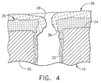
- the gas turbine engine component 16 has a body 30 with cooling holes 32 extending from an interior surface (not shown) of the component to an exterior surface 34 of the component.
- the apparatus 10 deposits a layer of thermal barrier coating, generally designated by 36, on the exterior surface 34 and the interior surface of the component 16 by a physical vapor deposition process. Because the cooling holes 32 are not masked during the physical vapor deposition process, a portion 38 of the thermal barrier coating 36 partially obstructs airflow through the cooling holes and coats the inside of the cooling holes, This portion 38 of the thermal barrier coating 36 reduces airflow through the cooling holes.
- a pressure flow stand is used to flow check the component 16 after depositing the thermal barrier coating 36 on the component.
- the stand 40 includes a compressor 42 connected to a duct 44.
- the component 16 is mounted on a bulkhead 46 positioned along the duct 44.
- An end of the duct opposite the compressor 42 is open.
- an end of the duct 48 upstream from the bulkhead 46 is pressurized and an end of the duct 50 downstream from the bulkhead 46 is at ambient pressure.
- a pressure probe 52 connected to the duct 48 measures pressure upstream from the bulkhead 46.
- airflow through the cooling holes can be calculated. This airflow is compared to a preselected range of desired cooling hole airflows. If the airflow is within the preselected range of desired cooling hole airflows and the component 16 otherwise meets component specifications, it is returned to service.
- the component 16 is loaded into the physical vapor deposition apparatus 10 and additional thermal barrier coating 36 is deposited on the component.
- the electron beam guns 20 are energized for a shorter period of time (e.g., between about 15 minutes and 30 minutes) than during the first deposition step.
- the coated component 16 is removed from the physical vapor deposition apparatus 10 and loaded into the pressure stand 40. Airflow through the cooling holes 32 is measured as before and the measured airflow is again compared to the preselected range. In one preferred embodiment of the present invention, these steps are repeated until the measured airflow is within the preselected range of desired cooling hole airflows.
- the time period during which the thermal barrier coating is deposited when repeating the steps is selected based on the measured airflow. It is envisioned that this time period can be determined from experience, and can be derived using empirical formulas. Preferably, the step of depositing the thermal barrier coating need be repeated no more than once during the second preferred embodiment. In a third preferred embodiment of the present invention, the time period during which the thermal barrier coating is deposited is determined before depositing the thermal barrier coating so the step of depositing the thermal barrier coating is performed only once.
- the minimum airflow of the preselected range of desired cooling airflows is selected to provide sufficient airflow through the cooling holes 32 to maintain the component 16 below a selected maximum temperature during engine operation.
- This maximum temperature is calculated to provide an environment in which component life requirements will be met.
- the maximum airflow of the range is selected to ensure sufficient cooling airflow through other components within the gas turbine engine to maintain the other components below maximum temperatures at which their respective life requirements are met.
- the method described above provides a gas turbine engine component 16 (Fig. 2) having more than one (and preferably only two) layer(s) of thermal barrier coating 36 applied to at least a portion of at least one of the surfaces of the component.
- Each of these layers of thermal barrier coating 36 at least partially obstructs the cooling holes 32 thereby reducing airflow through the cooling holes.
- eighty percent of the tested centerbodies had airflows nominally five percent above maximum allowable flow after a first coating 36 was applied. After a second coating 36 was applied, the centerbody airflows were reduced by about eight percent and were within specifications.
Landscapes
- Engineering & Computer Science (AREA)
- Chemical & Material Sciences (AREA)
- Mechanical Engineering (AREA)
- General Engineering & Computer Science (AREA)
- Materials Engineering (AREA)
- Chemical Kinetics & Catalysis (AREA)
- Metallurgy (AREA)
- Organic Chemistry (AREA)
- Turbine Rotor Nozzle Sealing (AREA)
- Application Of Or Painting With Fluid Materials (AREA)
- Sorption Type Refrigeration Machines (AREA)
- Separation By Low-Temperature Treatments (AREA)
Abstract
Description
Claims (10)
- A method of adjusting airflow through a plurality of cooling holes (32) extending through a gas turbine engine component (16) from an interior surface of the component (16) to an exterior surface (34) of the component (16), the method comprising the steps of:depositing a thermal barrier coating (36) on at least one of the exterior surface (34) and the interior surface of the component (16) by a physical vapor deposition process without masking said plurality of cooling holes (32) thereby permitting a portion (38) of the thermal barrier coating (36) to partially obstruct airflow through said plurality of cooling holes (32) and reducing airflow through said plurality of cooling holes (32);developing a predetermined pressure drop across said plurality of cooling holes (32) after depositing the thermal barrier coating (36) on the component (16);calculating airflow through said plurality of cooling holes (32) resulting from the predetermined pressure drop across said plurality of cooling holes (32);comparing the measured airflow through said plurality of cooling holes (32) to a preselected range of desired cooling hole airflows; andrepeating the steps of depositing the thermal barrier coating (36), developing the predetermined pressure drop, calculating airflow and comparing the measured airflow to the preselected range until the measured airflow is within the preselected range of desired cooling hole airflows.
- A method as set forth in claim 1 wherein said preselected range of desired cooling hole airflows includes a minimum airflow selected to provide sufficient airflow through said plurality of cooling holes (32) to maintain the component (16) below a maximum temperature at which component (16) life requirements are met.
- A method as set forth in claim 1 wherein said preselected range of desired cooling hole airflows includes a maximum airflow selected to ensure sufficient cooling airflow through other components within the gas turbine engine to maintain said other components below maximum temperatures at which their respective life requirements are met.
- A method as set forth in claim 1 wherein the step of repeating the steps is performed only once.
- A method as set forth in claim 1 wherein when repeating the steps the thermal barrier coating (36) is deposited for a period of time which is selected based on the measured airflow through said plurality of cooling holes (32).
- A method of adjusting airflow through a plurality of cooling holes (32) extending through a gas turbine engine component (16) from an interior surface of the component (16) to an exterior surface (34) of the component (16), the method comprising the steps of:depositing a thermal barrier coating (36) on at least one of the exterior surface (34) and the interior surface of the component (16) by a physical vapor deposition process without masking said plurality of cooling holes (32) thereby permitting a portion (38) of the thermal barrier coating (36) to partially obstruct airflow through said plurality of cooling holes (32) and reducing airflow through said plurality of cooling holes (32);developing a predetermined pressure drop across said plurality of cooling holes (32) after depositing the thermal barrier coating (36) on the component (16);calculating airflow through said plurality of cooling holes (32) resulting from the predetermined pressure drop across said plurality of cooling holes (32);selecting a period of time during which to deposit a second thermal barrier coating (36) based on the measured airflow through said plurality of cooling holes (32) so airflow through said plurality of cooling holes (32) after depositing said second thermal barrier coating (36) is within a preselected range of cooling hole airflows; anddepositing said second thermal barrier coating (36) for the selected period of time thereby obtaining airflow through said plurality of cooling holes (32) within the preselected range of cooling hole airflows.
- A method as set forth in claim 6 wherein said preselected range of desired cooling hole airflows includes a minimum airflow selected to provide sufficient airflow through said plurality of cooling holes (32) to maintain the component (16) below a maximum temperature at which component (16) life requirements are met.
- A method as set forth in claim 6 wherein said preselected range of desired cooling hole airflows includes a maximum airflow selected to ensure sufficient cooling airflow through other components within the gas turbine engine to maintain said other components below maximum temperatures at which their respective life requirements are met.
- A method of adjusting airflow through a plurality of cooling holes (32) extending through a gas turbine engine component (16) from an interior surface of the component (16) to an exterior surface (34) of the component (16), the method comprising the steps of:developing a predetermined pressure drop across said plurality of cooling holes (32);calculating airflow through said plurality of cooling holes (32) resulting from the predetermined pressure drop across said plurality of cooling holes (32);selecting a period of time during which to deposit a thermal barrier coating (36) based on the measured airflow through said plurality of cooling holes (32) so airflow through said plurality of cooling holes (32) after depositing said thermal barrier coating (36) is within a preselected range of cooling hole airflows; anddepositing the thermal barrier coating (36) on at least one of the exterior surface (34) and the interior surface of the component (16) for the selected period of time by a physical vapor deposition process without masking said plurality of cooling holes (32) thereby permitting a portion (38) of the thermal barrier coating (36) to partially obstruct airflow through said plurality of cooling holes (32) and reducing airflow through said plurality of cooling holes (32) thereby obtaining airflow through said plurality of cooling holes (32) within the preselected range of cooling hole airflows.
- A gas turbine engine component (16) comprising a body having a plurality of cooling holes (32) therein extending from an interior surface of the component (16) to an exterior surface (34) of the component (16), and a plurality of layers of thermal barrier coating (36) extending over at least a portion (38) of at least one of said interior and exterior surfaces, each of said plurality of layers of thermal barrier coating (36) at least partially obstructing airflow through said plurality of cooling holes (32) thereby reducing airflow through said plurality of cooling holes (32).
Applications Claiming Priority (2)
| Application Number | Priority Date | Filing Date | Title |
|---|---|---|---|
| US618571 | 2000-07-18 | ||
| US09/618,571 US6408610B1 (en) | 2000-07-18 | 2000-07-18 | Method of adjusting gas turbine component cooling air flow |
Publications (3)
| Publication Number | Publication Date |
|---|---|
| EP1174587A2 true EP1174587A2 (en) | 2002-01-23 |
| EP1174587A3 EP1174587A3 (en) | 2003-11-12 |
| EP1174587B1 EP1174587B1 (en) | 2006-05-17 |
Family
ID=24478242
Family Applications (1)
| Application Number | Title | Priority Date | Filing Date |
|---|---|---|---|
| EP01306168A Expired - Lifetime EP1174587B1 (en) | 2000-07-18 | 2001-07-18 | Method of adjusting component airflow |
Country Status (6)
| Country | Link |
|---|---|
| US (1) | US6408610B1 (en) |
| EP (1) | EP1174587B1 (en) |
| JP (1) | JP4776822B2 (en) |
| AT (1) | ATE326617T1 (en) |
| CA (1) | CA2352698C (en) |
| DE (1) | DE60119628T2 (en) |
Cited By (6)
| Publication number | Priority date | Publication date | Assignee | Title |
|---|---|---|---|---|
| DE10143153A1 (en) * | 2001-09-03 | 2003-03-20 | Rolls Royce Deutschland | Turbine blade for a gas turbine with at least one cooling recess |
| EP1533476A2 (en) | 2003-11-19 | 2005-05-25 | Massachussetts Institute of Technology | Method for assembling gas turbine engine components |
| WO2010142599A1 (en) * | 2009-06-12 | 2010-12-16 | Snecma | Method for reducing the diameter of an opening |
| EP2937513A3 (en) * | 2014-04-25 | 2016-02-17 | United Technologies Corporation | Method of forming a component and corresponding component |
| EP3058200A4 (en) * | 2013-10-18 | 2016-11-16 | United Technologies Corp | Turbine exhaust case with coated cooling holes |
| EP3561388A1 (en) * | 2018-04-23 | 2019-10-30 | Honeywell International Inc. | System and method for monitoring for sand plugging in gas turbine engines |
Families Citing this family (30)
| Publication number | Priority date | Publication date | Assignee | Title |
|---|---|---|---|---|
| US6499949B2 (en) * | 2001-03-27 | 2002-12-31 | Robert Edward Schafrik | Turbine airfoil trailing edge with micro cooling channels |
| US6551061B2 (en) * | 2001-03-27 | 2003-04-22 | General Electric Company | Process for forming micro cooling channels inside a thermal barrier coating system without masking material |
| US6761956B2 (en) * | 2001-12-20 | 2004-07-13 | General Electric Company | Ventilated thermal barrier coating |
| US6640546B2 (en) * | 2001-12-20 | 2003-11-04 | General Electric Company | Foil formed cooling area enhancement |
| US6749396B2 (en) | 2002-06-17 | 2004-06-15 | General Electric Company | Failsafe film cooled wall |
| US6723951B1 (en) | 2003-06-04 | 2004-04-20 | Siemens Westinghouse Power Corporation | Method for reestablishing holes in a component |
| RU2267615C1 (en) * | 2004-05-21 | 2006-01-10 | Федеральное государственное унитарное предприятие "Центральный институт авиационного моторостроения им. П.И. Баранова" | Turbine blade |
| US20060016191A1 (en) * | 2004-07-23 | 2006-01-26 | Honeywell International Inc. | Combined effusion and thick TBC cooling method |
| US7216485B2 (en) * | 2004-09-03 | 2007-05-15 | General Electric Company | Adjusting airflow in turbine component by depositing overlay metallic coating |
| US7186091B2 (en) * | 2004-11-09 | 2007-03-06 | General Electric Company | Methods and apparatus for cooling gas turbine engine components |
| GB2428608A (en) * | 2005-07-30 | 2007-02-07 | Siemens Ind Turbomachinery Ltd | A method for production of a set of holes by monitoring fluid flow |
| GB2429515B (en) * | 2005-08-11 | 2008-06-25 | Rolls Royce Plc | Cooling method and apparatus |
| US20090142548A1 (en) * | 2007-10-18 | 2009-06-04 | David Bruce Patterson | Air cooled gas turbine components and methods of manufacturing and repairing the same |
| US20090226327A1 (en) * | 2008-03-07 | 2009-09-10 | Siemens Power Generation, Inc. | Gas Turbine Engine Including Temperature Control Device and Method Using Memory Metal |
| US20100329887A1 (en) * | 2009-06-26 | 2010-12-30 | Andy Eifert | Coolable gas turbine engine component |
| US8460760B2 (en) | 2010-11-30 | 2013-06-11 | United Technologies Corporation | Coating a perforated surface |
| US10060630B2 (en) * | 2012-10-01 | 2018-08-28 | Ansaldo Energia Ip Uk Limited | Flamesheet combustor contoured liner |
| US20140174091A1 (en) * | 2012-12-21 | 2014-06-26 | United Technologies Corporation | Repair procedure for a gas turbine engine via variable polarity welding |
| US20160237950A1 (en) * | 2013-10-07 | 2016-08-18 | United Technologies Corporation | Backside coating cooling passage |
| US10704424B2 (en) * | 2013-11-04 | 2020-07-07 | Raytheon Technologies Corporation | Coated cooling passage |
| US9744614B2 (en) * | 2013-11-18 | 2017-08-29 | General Electric Company | Method for modifying an aperture and system for modifying flow through a component |
| FR3013996B1 (en) | 2013-12-02 | 2017-04-28 | Office National Detudes Et De Rech Aerospatiales Onera | PROCESS FOR THE LOCAL REPAIR OF THERMAL BARRIERS |
| FR3014115B1 (en) | 2013-12-02 | 2017-04-28 | Office National Detudes Et De Rech Aerospatiales Onera | METHOD AND SYSTEM FOR OXIDE DEPOSITION ON POROUS COMPONENT |
| US9151175B2 (en) * | 2014-02-25 | 2015-10-06 | Siemens Aktiengesellschaft | Turbine abradable layer with progressive wear zone multi level ridge arrays |
| US10934853B2 (en) | 2014-07-03 | 2021-03-02 | Rolls-Royce Corporation | Damage tolerant cooling of high temperature mechanical system component including a coating |
| US9869183B2 (en) * | 2014-08-01 | 2018-01-16 | United Technologies Corporation | Thermal barrier coating inside cooling channels |
| KR102405991B1 (en) * | 2014-11-21 | 2022-06-10 | 에이치2 아이피 유케이 리미티드 | Flamesheet combustor contoured liner |
| US10829845B2 (en) * | 2017-01-06 | 2020-11-10 | General Electric Company | Selective thermal coating of cooling holes with air flow |
| US11286792B2 (en) * | 2019-07-30 | 2022-03-29 | Rolls-Royce Plc | Ceramic matrix composite vane with cooling holes and methods of making the same |
| US11585224B2 (en) | 2020-08-07 | 2023-02-21 | General Electric Company | Gas turbine engines and methods associated therewith |
Family Cites Families (16)
| Publication number | Priority date | Publication date | Assignee | Title |
|---|---|---|---|---|
| JP2695835B2 (en) * | 1988-05-06 | 1998-01-14 | 株式会社日立製作所 | Ceramic coated heat resistant material |
| US5247766A (en) * | 1992-01-31 | 1993-09-28 | Kildea Robert J | Process for improving cooling hole flow control |
| US5350599A (en) * | 1992-10-27 | 1994-09-27 | General Electric Company | Erosion-resistant thermal barrier coating |
| JPH07286503A (en) * | 1994-04-20 | 1995-10-31 | Hitachi Ltd | High efficiency gas turbine |
| DE69524353T2 (en) * | 1994-10-04 | 2002-08-08 | General Electric Co., Schenectady | High-temperature protective layer |
| WO1996011288A1 (en) * | 1994-10-05 | 1996-04-18 | United Technologies Corporation | Multiple nanolayer coating system |
| KR100463008B1 (en) * | 1995-06-26 | 2005-06-16 | 제너럴 일렉트릭 캄파니 | Protected Thermal Barrier Coating Composite With Multiple Coatings |
| US5724816A (en) * | 1996-04-10 | 1998-03-10 | General Electric Company | Combustor for a gas turbine with cooling structure |
| US5682747A (en) * | 1996-04-10 | 1997-11-04 | General Electric Company | Gas turbine combustor heat shield of casted super alloy |
| US5771577A (en) * | 1996-05-17 | 1998-06-30 | General Electric Company | Method for making a fluid cooled article with protective coating |
| US5822853A (en) * | 1996-06-24 | 1998-10-20 | General Electric Company | Method for making cylindrical structures with cooling channels |
| JP2001521989A (en) * | 1997-11-03 | 2001-11-13 | シーメンス アクチエンゲゼルシヤフト | Method for forming a film and apparatus for performing the method |
| GB9723762D0 (en) * | 1997-11-12 | 1998-01-07 | Rolls Royce Plc | A method of coating a component |
| DE19859763A1 (en) * | 1998-12-23 | 2000-06-29 | Abb Alstom Power Ch Ag | Process for neutralizing constrictions in the cooling holes of gas-cooled parts that occur when coating with a protective layer |
| US6210488B1 (en) * | 1998-12-30 | 2001-04-03 | General Electric Company | Method of removing a thermal barrier coating |
| US6126400A (en) * | 1999-02-01 | 2000-10-03 | General Electric Company | Thermal barrier coating wrap for turbine airfoil |
-
2000
- 2000-07-18 US US09/618,571 patent/US6408610B1/en not_active Expired - Fee Related
-
2001
- 2001-07-05 CA CA002352698A patent/CA2352698C/en not_active Expired - Fee Related
- 2001-07-17 JP JP2001216071A patent/JP4776822B2/en not_active Expired - Fee Related
- 2001-07-18 EP EP01306168A patent/EP1174587B1/en not_active Expired - Lifetime
- 2001-07-18 DE DE60119628T patent/DE60119628T2/en not_active Expired - Lifetime
- 2001-07-18 AT AT01306168T patent/ATE326617T1/en not_active IP Right Cessation
Cited By (11)
| Publication number | Priority date | Publication date | Assignee | Title |
|---|---|---|---|---|
| DE10143153A1 (en) * | 2001-09-03 | 2003-03-20 | Rolls Royce Deutschland | Turbine blade for a gas turbine with at least one cooling recess |
| US6817833B2 (en) | 2001-09-03 | 2004-11-16 | Rolls-Royce Deutschland Ltd & Co Kg | Turbine blade of a gas turbine with at least one cooling excavation |
| EP1533476A2 (en) | 2003-11-19 | 2005-05-25 | Massachussetts Institute of Technology | Method for assembling gas turbine engine components |
| EP1533476A3 (en) * | 2003-11-19 | 2008-12-10 | Massachussetts Institute of Technology | Method for assembling gas turbine engine components |
| WO2010142599A1 (en) * | 2009-06-12 | 2010-12-16 | Snecma | Method for reducing the diameter of an opening |
| FR2946555A1 (en) * | 2009-06-12 | 2010-12-17 | Snecma | METHOD FOR REDUCING THE DIAMETER OF AN ORIFICE |
| CN102458756A (en) * | 2009-06-12 | 2012-05-16 | 斯奈克玛 | Method of reducing opening diameter |
| EP3058200A4 (en) * | 2013-10-18 | 2016-11-16 | United Technologies Corp | Turbine exhaust case with coated cooling holes |
| EP2937513A3 (en) * | 2014-04-25 | 2016-02-17 | United Technologies Corporation | Method of forming a component and corresponding component |
| EP3561388A1 (en) * | 2018-04-23 | 2019-10-30 | Honeywell International Inc. | System and method for monitoring for sand plugging in gas turbine engines |
| US10900377B2 (en) | 2018-04-23 | 2021-01-26 | Honeywell International Inc. | System and method for monitoring for sand plugging in gas turbine engines |
Also Published As
| Publication number | Publication date |
|---|---|
| DE60119628T2 (en) | 2007-03-08 |
| CA2352698A1 (en) | 2002-01-18 |
| US6408610B1 (en) | 2002-06-25 |
| DE60119628D1 (en) | 2006-06-22 |
| CA2352698C (en) | 2008-06-17 |
| ATE326617T1 (en) | 2006-06-15 |
| EP1174587A3 (en) | 2003-11-12 |
| JP2002097968A (en) | 2002-04-05 |
| EP1174587B1 (en) | 2006-05-17 |
| JP4776822B2 (en) | 2011-09-21 |
Similar Documents
| Publication | Publication Date | Title |
|---|---|---|
| EP1174587B1 (en) | Method of adjusting component airflow | |
| CA2517080C (en) | Adjusting airflow in turbine component by depositing overlay metallic coating | |
| CN1740641B (en) | Combustor member and method for making a combustor assembly | |
| US6042880A (en) | Renewing a thermal barrier coating system | |
| US6364608B1 (en) | Partially coated airfoil and method for making | |
| US6042898A (en) | Method for applying improved durability thermal barrier coatings | |
| US5702288A (en) | Method of removing excess overlay coating from within cooling holes of aluminide coated gas turbine engine components | |
| EP1245787B1 (en) | Cooling system for a coated turbine blade tip | |
| US5614054A (en) | Process for removing a thermal barrier coating | |
| RU2485206C2 (en) | Method for aluminising from vapour phase of metal part of gas-turbine engine, donor jacket and blade of gas-turbine engine, which contains such jacket | |
| US20070036942A1 (en) | Cooling method and apparatus | |
| US6434823B1 (en) | Method for repairing a coated article | |
| US20240052497A1 (en) | Cmas-resistant thermal barrier coating for part of gas turbine engine | |
| US20200001404A1 (en) | Method for repairing a part | |
| US5780106A (en) | Method for low temperature aluminum coating of an article | |
| GB2117269A (en) | Thermal barrier coating | |
| US20040048003A1 (en) | Method for coating a substrate having holes | |
| US20040159552A1 (en) | Method of depositing a local MCrAIY-coating | |
| US20150308937A1 (en) | Method of testing the oxidation resistance of an alloy | |
| Bunker | The effect of thermal barrier coating roughness magnitude on heat transfer with and without flowpath surface steps | |
| WO2005038074A1 (en) | Method of applying a thermal barrier coating system to a superalloy substrate | |
| US9932665B2 (en) | Corrosion resistant coating application method | |
| EP1852524A2 (en) | Method for manufacturing thermal barrier coatings with improved thermal insulation characteristics | |
| Gogidze et al. | Effect of Dust Chemistry on Cyclic Deposition in an Impingement/Effusion Cooling Geometry | |
| Kool et al. | Operational Experience With Internal Coatings in Aero-and Industrial Gas Turbine Airfoils |
Legal Events
| Date | Code | Title | Description |
|---|---|---|---|
| PUAI | Public reference made under article 153(3) epc to a published international application that has entered the european phase |
Free format text: ORIGINAL CODE: 0009012 |
|
| AK | Designated contracting states |
Kind code of ref document: A2 Designated state(s): AT BE CH CY DE DK ES FI FR GB GR IE IT LI LU MC NL PT SE TR |
|
| AX | Request for extension of the european patent |
Free format text: AL;LT;LV;MK;RO;SI |
|
| PUAL | Search report despatched |
Free format text: ORIGINAL CODE: 0009013 |
|
| AK | Designated contracting states |
Kind code of ref document: A3 Designated state(s): AT BE CH CY DE DK ES FI FR GB GR IE IT LI LU MC NL PT SE TR |
|
| AX | Request for extension of the european patent |
Extension state: AL LT LV MK RO SI |
|
| RIC1 | Information provided on ipc code assigned before grant |
Ipc: 7F 01D 5/18 A Ipc: 7C 23C 16/04 B Ipc: 7C 23C 4/00 B Ipc: 7F 01D 5/28 B |
|
| 17P | Request for examination filed |
Effective date: 20040512 |
|
| AKX | Designation fees paid |
Designated state(s): AT BE CH CY DE DK ES FI FR GB GR IE IT LI LU MC NL PT SE TR |
|
| 17Q | First examination report despatched |
Effective date: 20050203 |
|
| GRAP | Despatch of communication of intention to grant a patent |
Free format text: ORIGINAL CODE: EPIDOSNIGR1 |
|
| GRAS | Grant fee paid |
Free format text: ORIGINAL CODE: EPIDOSNIGR3 |
|
| GRAA | (expected) grant |
Free format text: ORIGINAL CODE: 0009210 |
|
| AK | Designated contracting states |
Kind code of ref document: B1 Designated state(s): AT BE CH CY DE DK ES FI FR GB GR IE IT LI LU MC NL PT SE TR |
|
| PG25 | Lapsed in a contracting state [announced via postgrant information from national office to epo] |
Ref country code: BE Free format text: LAPSE BECAUSE OF FAILURE TO SUBMIT A TRANSLATION OF THE DESCRIPTION OR TO PAY THE FEE WITHIN THE PRESCRIBED TIME-LIMIT Effective date: 20060517 Ref country code: LI Free format text: LAPSE BECAUSE OF FAILURE TO SUBMIT A TRANSLATION OF THE DESCRIPTION OR TO PAY THE FEE WITHIN THE PRESCRIBED TIME-LIMIT Effective date: 20060517 Ref country code: AT Free format text: LAPSE BECAUSE OF FAILURE TO SUBMIT A TRANSLATION OF THE DESCRIPTION OR TO PAY THE FEE WITHIN THE PRESCRIBED TIME-LIMIT Effective date: 20060517 Ref country code: FI Free format text: LAPSE BECAUSE OF FAILURE TO SUBMIT A TRANSLATION OF THE DESCRIPTION OR TO PAY THE FEE WITHIN THE PRESCRIBED TIME-LIMIT Effective date: 20060517 Ref country code: CH Free format text: LAPSE BECAUSE OF FAILURE TO SUBMIT A TRANSLATION OF THE DESCRIPTION OR TO PAY THE FEE WITHIN THE PRESCRIBED TIME-LIMIT Effective date: 20060517 |
|
| REG | Reference to a national code |
Ref country code: GB Ref legal event code: FG4D |
|
| REG | Reference to a national code |
Ref country code: CH Ref legal event code: EP |
|
| REG | Reference to a national code |
Ref country code: IE Ref legal event code: FG4D |
|
| REF | Corresponds to: |
Ref document number: 60119628 Country of ref document: DE Date of ref document: 20060622 Kind code of ref document: P |
|
| PGFP | Annual fee paid to national office [announced via postgrant information from national office to epo] |
Ref country code: IE Payment date: 20060726 Year of fee payment: 6 |
|
| PG25 | Lapsed in a contracting state [announced via postgrant information from national office to epo] |
Ref country code: MC Free format text: LAPSE BECAUSE OF NON-PAYMENT OF DUE FEES Effective date: 20060731 |
|
| PG25 | Lapsed in a contracting state [announced via postgrant information from national office to epo] |
Ref country code: SE Free format text: LAPSE BECAUSE OF FAILURE TO SUBMIT A TRANSLATION OF THE DESCRIPTION OR TO PAY THE FEE WITHIN THE PRESCRIBED TIME-LIMIT Effective date: 20060817 Ref country code: DK Free format text: LAPSE BECAUSE OF FAILURE TO SUBMIT A TRANSLATION OF THE DESCRIPTION OR TO PAY THE FEE WITHIN THE PRESCRIBED TIME-LIMIT Effective date: 20060817 |
|
| PG25 | Lapsed in a contracting state [announced via postgrant information from national office to epo] |
Ref country code: ES Free format text: LAPSE BECAUSE OF FAILURE TO SUBMIT A TRANSLATION OF THE DESCRIPTION OR TO PAY THE FEE WITHIN THE PRESCRIBED TIME-LIMIT Effective date: 20060828 |
|
| PG25 | Lapsed in a contracting state [announced via postgrant information from national office to epo] |
Ref country code: PT Free format text: LAPSE BECAUSE OF FAILURE TO SUBMIT A TRANSLATION OF THE DESCRIPTION OR TO PAY THE FEE WITHIN THE PRESCRIBED TIME-LIMIT Effective date: 20061017 |
|
| REG | Reference to a national code |
Ref country code: CH Ref legal event code: PL |
|
| ET | Fr: translation filed | ||
| PLBE | No opposition filed within time limit |
Free format text: ORIGINAL CODE: 0009261 |
|
| STAA | Information on the status of an ep patent application or granted ep patent |
Free format text: STATUS: NO OPPOSITION FILED WITHIN TIME LIMIT |
|
| 26N | No opposition filed |
Effective date: 20070220 |
|
| PG25 | Lapsed in a contracting state [announced via postgrant information from national office to epo] |
Ref country code: GR Free format text: LAPSE BECAUSE OF FAILURE TO SUBMIT A TRANSLATION OF THE DESCRIPTION OR TO PAY THE FEE WITHIN THE PRESCRIBED TIME-LIMIT Effective date: 20060818 |
|
| PG25 | Lapsed in a contracting state [announced via postgrant information from national office to epo] |
Ref country code: LU Free format text: LAPSE BECAUSE OF NON-PAYMENT OF DUE FEES Effective date: 20060718 |
|
| PG25 | Lapsed in a contracting state [announced via postgrant information from national office to epo] |
Ref country code: IE Free format text: LAPSE BECAUSE OF NON-PAYMENT OF DUE FEES Effective date: 20070718 |
|
| PG25 | Lapsed in a contracting state [announced via postgrant information from national office to epo] |
Ref country code: CY Free format text: LAPSE BECAUSE OF FAILURE TO SUBMIT A TRANSLATION OF THE DESCRIPTION OR TO PAY THE FEE WITHIN THE PRESCRIBED TIME-LIMIT Effective date: 20060517 |
|
| PG25 | Lapsed in a contracting state [announced via postgrant information from national office to epo] |
Ref country code: TR Free format text: LAPSE BECAUSE OF FAILURE TO SUBMIT A TRANSLATION OF THE DESCRIPTION OR TO PAY THE FEE WITHIN THE PRESCRIBED TIME-LIMIT Effective date: 20060517 |
|
| PGFP | Annual fee paid to national office [announced via postgrant information from national office to epo] |
Ref country code: GB Payment date: 20120725 Year of fee payment: 12 |
|
| PGFP | Annual fee paid to national office [announced via postgrant information from national office to epo] |
Ref country code: FR Payment date: 20120731 Year of fee payment: 12 Ref country code: DE Payment date: 20120727 Year of fee payment: 12 Ref country code: IT Payment date: 20120723 Year of fee payment: 12 |
|
| PGFP | Annual fee paid to national office [announced via postgrant information from national office to epo] |
Ref country code: NL Payment date: 20120724 Year of fee payment: 12 |
|
| REG | Reference to a national code |
Ref country code: NL Ref legal event code: V1 Effective date: 20140201 |
|
| GBPC | Gb: european patent ceased through non-payment of renewal fee |
Effective date: 20130718 |
|
| REG | Reference to a national code |
Ref country code: FR Ref legal event code: ST Effective date: 20140331 |
|
| PG25 | Lapsed in a contracting state [announced via postgrant information from national office to epo] |
Ref country code: GB Free format text: LAPSE BECAUSE OF NON-PAYMENT OF DUE FEES Effective date: 20130718 Ref country code: DE Free format text: LAPSE BECAUSE OF NON-PAYMENT OF DUE FEES Effective date: 20140201 Ref country code: NL Free format text: LAPSE BECAUSE OF NON-PAYMENT OF DUE FEES Effective date: 20140201 |
|
| REG | Reference to a national code |
Ref country code: DE Ref legal event code: R119 Ref document number: 60119628 Country of ref document: DE Effective date: 20140201 |
|
| PG25 | Lapsed in a contracting state [announced via postgrant information from national office to epo] |
Ref country code: FR Free format text: LAPSE BECAUSE OF NON-PAYMENT OF DUE FEES Effective date: 20130731 Ref country code: IT Free format text: LAPSE BECAUSE OF NON-PAYMENT OF DUE FEES Effective date: 20130718 |