EP1174270A1 - Rotating disk cleaning assembly apparatus and method for an inkjet print head with fixed gutter - Google Patents
Rotating disk cleaning assembly apparatus and method for an inkjet print head with fixed gutter Download PDFInfo
- Publication number
- EP1174270A1 EP1174270A1 EP01202523A EP01202523A EP1174270A1 EP 1174270 A1 EP1174270 A1 EP 1174270A1 EP 01202523 A EP01202523 A EP 01202523A EP 01202523 A EP01202523 A EP 01202523A EP 1174270 A1 EP1174270 A1 EP 1174270A1
- Authority
- EP
- European Patent Office
- Prior art keywords
- print head
- cleaning
- rotating disk
- cleaning assembly
- ink jet
- Prior art date
- Legal status (The legal status is an assumption and is not a legal conclusion. Google has not performed a legal analysis and makes no representation as to the accuracy of the status listed.)
- Withdrawn
Links
- 238000004140 cleaning Methods 0.000 title claims abstract description 153
- 238000000034 method Methods 0.000 title description 13
- 239000007788 liquid Substances 0.000 claims abstract description 42
- 239000000356 contaminant Substances 0.000 claims abstract description 26
- 230000002745 absorbent Effects 0.000 claims description 14
- 239000002250 absorbent Substances 0.000 claims description 14
- 238000007639 printing Methods 0.000 claims description 11
- 238000012423 maintenance Methods 0.000 claims description 2
- 230000007246 mechanism Effects 0.000 abstract description 18
- 239000000976 ink Substances 0.000 description 92
- 239000000463 material Substances 0.000 description 11
- 238000010586 diagram Methods 0.000 description 5
- 229910052751 metal Inorganic materials 0.000 description 4
- 239000002184 metal Substances 0.000 description 4
- 239000002245 particle Substances 0.000 description 4
- 239000013618 particulate matter Substances 0.000 description 4
- 238000013519 translation Methods 0.000 description 4
- 230000009471 action Effects 0.000 description 3
- 230000008901 benefit Effects 0.000 description 3
- 230000015572 biosynthetic process Effects 0.000 description 3
- MTHSVFCYNBDYFN-UHFFFAOYSA-N diethylene glycol Chemical compound OCCOCCO MTHSVFCYNBDYFN-UHFFFAOYSA-N 0.000 description 3
- 238000012545 processing Methods 0.000 description 3
- 238000004064 recycling Methods 0.000 description 3
- 239000002904 solvent Substances 0.000 description 3
- 238000012546 transfer Methods 0.000 description 3
- LYCAIKOWRPUZTN-UHFFFAOYSA-N Ethylene glycol Chemical compound OCCO LYCAIKOWRPUZTN-UHFFFAOYSA-N 0.000 description 2
- KFZMGEQAYNKOFK-UHFFFAOYSA-N Isopropanol Chemical compound CC(C)O KFZMGEQAYNKOFK-UHFFFAOYSA-N 0.000 description 2
- XUIMIQQOPSSXEZ-UHFFFAOYSA-N Silicon Chemical compound [Si] XUIMIQQOPSSXEZ-UHFFFAOYSA-N 0.000 description 2
- 239000000428 dust Substances 0.000 description 2
- 230000005684 electric field Effects 0.000 description 2
- 239000004519 grease Substances 0.000 description 2
- 238000010438 heat treatment Methods 0.000 description 2
- 239000000203 mixture Substances 0.000 description 2
- 229920003023 plastic Polymers 0.000 description 2
- 239000004033 plastic Substances 0.000 description 2
- 238000007790 scraping Methods 0.000 description 2
- 229910052710 silicon Inorganic materials 0.000 description 2
- 239000010703 silicon Substances 0.000 description 2
- 239000004094 surface-active agent Substances 0.000 description 2
- 238000009736 wetting Methods 0.000 description 2
- 239000002253 acid Substances 0.000 description 1
- 150000007513 acids Chemical class 0.000 description 1
- 230000000712 assembly Effects 0.000 description 1
- 238000000429 assembly Methods 0.000 description 1
- 229910002113 barium titanate Inorganic materials 0.000 description 1
- JRPBQTZRNDNNOP-UHFFFAOYSA-N barium titanate Chemical compound [Ba+2].[Ba+2].[O-][Ti]([O-])([O-])[O-] JRPBQTZRNDNNOP-UHFFFAOYSA-N 0.000 description 1
- 239000002585 base Substances 0.000 description 1
- 230000001680 brushing effect Effects 0.000 description 1
- 239000000919 ceramic Substances 0.000 description 1
- 230000008859 change Effects 0.000 description 1
- 238000007600 charging Methods 0.000 description 1
- 238000011109 contamination Methods 0.000 description 1
- 238000013461 design Methods 0.000 description 1
- 229940028356 diethylene glycol monobutyl ether Drugs 0.000 description 1
- NKZSPGSOXYXWQA-UHFFFAOYSA-N dioxido(oxo)titanium;lead(2+) Chemical compound [Pb+2].[O-][Ti]([O-])=O NKZSPGSOXYXWQA-UHFFFAOYSA-N 0.000 description 1
- 238000001035 drying Methods 0.000 description 1
- 238000007786 electrostatic charging Methods 0.000 description 1
- 238000005516 engineering process Methods 0.000 description 1
- -1 felt Substances 0.000 description 1
- 230000006870 function Effects 0.000 description 1
- WGCNASOHLSPBMP-UHFFFAOYSA-N hydroxyacetaldehyde Natural products OCC=O WGCNASOHLSPBMP-UHFFFAOYSA-N 0.000 description 1
- 238000007641 inkjet printing Methods 0.000 description 1
- 238000010030 laminating Methods 0.000 description 1
- 229910052451 lead zirconate titanate Inorganic materials 0.000 description 1
- HFGPZNIAWCZYJU-UHFFFAOYSA-N lead zirconate titanate Chemical compound [O-2].[O-2].[O-2].[O-2].[O-2].[Ti+4].[Zr+4].[Pb+2] HFGPZNIAWCZYJU-UHFFFAOYSA-N 0.000 description 1
- 238000005461 lubrication Methods 0.000 description 1
- 239000004530 micro-emulsion Substances 0.000 description 1
- 238000012986 modification Methods 0.000 description 1
- 230000004048 modification Effects 0.000 description 1
- TVMXDCGIABBOFY-UHFFFAOYSA-N octane Chemical compound CCCCCCCC TVMXDCGIABBOFY-UHFFFAOYSA-N 0.000 description 1
- JCGNDDUYTRNOFT-UHFFFAOYSA-N oxolane-2,4-dione Chemical compound O=C1COC(=O)C1 JCGNDDUYTRNOFT-UHFFFAOYSA-N 0.000 description 1
- 229920001343 polytetrafluoroethylene Polymers 0.000 description 1
- 229920002635 polyurethane Polymers 0.000 description 1
- 239000004814 polyurethane Substances 0.000 description 1
- 238000003825 pressing Methods 0.000 description 1
- 230000008569 process Effects 0.000 description 1
- 239000010453 quartz Substances 0.000 description 1
- VYPSYNLAJGMNEJ-UHFFFAOYSA-N silicon dioxide Inorganic materials O=[Si]=O VYPSYNLAJGMNEJ-UHFFFAOYSA-N 0.000 description 1
- 239000007787 solid Substances 0.000 description 1
- 238000005507 spraying Methods 0.000 description 1
- 239000000126 substance Substances 0.000 description 1
- 239000000758 substrate Substances 0.000 description 1
- 239000011032 tourmaline Substances 0.000 description 1
- 229940070527 tourmaline Drugs 0.000 description 1
- 229910052613 tourmaline Inorganic materials 0.000 description 1
- XLYOFNOQVPJJNP-UHFFFAOYSA-N water Substances O XLYOFNOQVPJJNP-UHFFFAOYSA-N 0.000 description 1
Images






Classifications
-
- B—PERFORMING OPERATIONS; TRANSPORTING
- B41—PRINTING; LINING MACHINES; TYPEWRITERS; STAMPS
- B41J—TYPEWRITERS; SELECTIVE PRINTING MECHANISMS, i.e. MECHANISMS PRINTING OTHERWISE THAN FROM A FORME; CORRECTION OF TYPOGRAPHICAL ERRORS
- B41J2/00—Typewriters or selective printing mechanisms characterised by the printing or marking process for which they are designed
- B41J2/005—Typewriters or selective printing mechanisms characterised by the printing or marking process for which they are designed characterised by bringing liquid or particles selectively into contact with a printing material
- B41J2/01—Ink jet
- B41J2/015—Ink jet characterised by the jet generation process
- B41J2/02—Ink jet characterised by the jet generation process generating a continuous ink jet
- B41J2/03—Ink jet characterised by the jet generation process generating a continuous ink jet by pressure
-
- B—PERFORMING OPERATIONS; TRANSPORTING
- B41—PRINTING; LINING MACHINES; TYPEWRITERS; STAMPS
- B41J—TYPEWRITERS; SELECTIVE PRINTING MECHANISMS, i.e. MECHANISMS PRINTING OTHERWISE THAN FROM A FORME; CORRECTION OF TYPOGRAPHICAL ERRORS
- B41J2/00—Typewriters or selective printing mechanisms characterised by the printing or marking process for which they are designed
- B41J2/005—Typewriters or selective printing mechanisms characterised by the printing or marking process for which they are designed characterised by bringing liquid or particles selectively into contact with a printing material
- B41J2/01—Ink jet
- B41J2/135—Nozzles
- B41J2/165—Prevention or detection of nozzle clogging, e.g. cleaning, capping or moistening for nozzles
- B41J2/16517—Cleaning of print head nozzles
- B41J2/16552—Cleaning of print head nozzles using cleaning fluids
-
- B—PERFORMING OPERATIONS; TRANSPORTING
- B41—PRINTING; LINING MACHINES; TYPEWRITERS; STAMPS
- B41J—TYPEWRITERS; SELECTIVE PRINTING MECHANISMS, i.e. MECHANISMS PRINTING OTHERWISE THAN FROM A FORME; CORRECTION OF TYPOGRAPHICAL ERRORS
- B41J2/00—Typewriters or selective printing mechanisms characterised by the printing or marking process for which they are designed
- B41J2/005—Typewriters or selective printing mechanisms characterised by the printing or marking process for which they are designed characterised by bringing liquid or particles selectively into contact with a printing material
- B41J2/01—Ink jet
- B41J2/17—Ink jet characterised by ink handling
- B41J2/1714—Conditioning of the outside of ink supply systems, e.g. inkjet collector cleaning, ink mist removal
-
- B—PERFORMING OPERATIONS; TRANSPORTING
- B41—PRINTING; LINING MACHINES; TYPEWRITERS; STAMPS
- B41J—TYPEWRITERS; SELECTIVE PRINTING MECHANISMS, i.e. MECHANISMS PRINTING OTHERWISE THAN FROM A FORME; CORRECTION OF TYPOGRAPHICAL ERRORS
- B41J2/00—Typewriters or selective printing mechanisms characterised by the printing or marking process for which they are designed
- B41J2/005—Typewriters or selective printing mechanisms characterised by the printing or marking process for which they are designed characterised by bringing liquid or particles selectively into contact with a printing material
- B41J2/01—Ink jet
- B41J2/015—Ink jet characterised by the jet generation process
- B41J2/02—Ink jet characterised by the jet generation process generating a continuous ink jet
- B41J2/03—Ink jet characterised by the jet generation process generating a continuous ink jet by pressure
- B41J2002/032—Deflection by heater around the nozzle
Definitions
- This invention generally relates to a self-cleaning ink jet printer and methods for cleaning the same, and more particularly to a rotating disk cleaning assembly for an ink jet printer having a fixed canopy-type gutter.
- An ink jet printer produces images by ejecting ink droplets onto a receiver medium in an image-wise fashion.
- the advantages of non-impact, low-noise, low energy use, and low cost operation in addition to the capability of the printer to print on plain paper mediums are largely responsible for the wide acceptance of ink jet printers in the marketplace.
- On demand ink jet printers utilize a pressurization actuator to produce the ink jet droplet at orifices of a print head.
- actuators either one of two types of actuators may be used including heat actuators and piezoelectric actuators.
- heat actuators a heater placed at a convenient location heats the ink and a quantity of the ink will phase change into a gaseous steam bubble and raise the internal ink pressure sufficiently for an ink droplet to be expelled onto the recording medium.
- piezoelectric actuators a piezoelectric material possessing properties such that an electric field is produced when a mechanical stress is applied. The converse also holds true; that is, an applied electric field will produce a mechanical stress in the material. Some naturally occurring materials possessing these characteristics are quartz and tourmaline. The most commonly produced piezoelectric ceramics are lead zirconate titanate, barium titanate, lead titanate, and lead metaniobate.
- electrostatic charging tunnels are placed close to the point where ink droplets are being ejected in the form of a stream. Selected droplets are electrically charged by the charging tunnels. The charged droplets are deflected downstream by the presence of deflector plates that have a predetermined electric potential difference between them. A gutter may be used to intercept the charged droplets, while the uncharged droplets are free to strike the recording medium.
- Inks for high-speed ink jet printers must have a number of special characteristics.
- the ink should incorporate a nondrying characteristic, so that drying of ink in the ink ejection chamber is hindered or slowed to such a state that by occasional spitting of ink droplets, the cavities and corresponding nozzles are kept open.
- glycol facilitates free flow of ink through the ink jet chamber.
- the ink jet print head is exposed to the environment where the ink jet printing occurs.
- the previously mentioned nozzles are exposed to many kinds of air born particulates. Particulate debris may accumulate on surfaces formed around the nozzles and may accumulate in the nozzles and chambers themselves.
- the ink may combine with such particulate debris to form an interference burr that blocks the nozzle or that alters surface wetting to inhibit proper formation of the ink droplet.
- the particulate debris should be cleaned from the surface and nozzle to restore proper droplet formation. In the prior art, this cleaning is commonly accomplished by brushing, wiping, spraying, vacuum suction, and/or spitting of ink through the nozzle.
- ink jet printers can be said to have the following problems: the inks tend to dry-out in and around the nozzles resulting in clogging of the nozzles; and the wiping of the nozzle plate causes wear on plate and wiper, the wiper itself producing particles that clog the nozzle.
- cleaning an ink jet nozzle plate that has limited accessibility due to the placement of a fixed gutter poses extra demands on the design of cleaning members and on methods used.
- Ink jet print head cleaners are known.
- a print head wiping system for ink jet print heads is disclosed in U.S. Patent 5,614,930, entitled "Orthogonal Rotary Wiping System For Ink jet Printheads" issued March 25,1997 in the name of William S. Osborne et al.
- the Osborne et al. patent discloses a rotary service station, which incorporates a wiper-supporting tumbler. The tumbler rotates to wipe the print head along a length of a linearly aligned nozzle.
- a wiper scraping system scrapes the wipers to clean the wipers.
- Osborne et al. do not disclose use of an external solvent to assist cleaning and also does not disclose complete removal of the external solvent.
- a wiper scraping system is limited by the size constraints imposed by the print head itself. This is particularly true for fixed gutter ink jet print head systems, which partially encloses the print head surfaces. Fixed gutter systems require a mechanism that can work within small tolerances imposed by the integrated gutter in order to clean the print head. The Osborne et al. cannot tolerate the stresses demanded by the tight spacing and limited size of current ink jet print heads.
- the cleaning mechanism composed of a rotating disk cleaning assembly for use in a self-cleaning printer.
- the self-cleaning printer includes a print head having a print head surface and an ink channel therein, and a structural member that functions as a gutter for collecting ink disposed opposite to the print head surface.
- the cleaning mechanism is adapted to clean contaminant from the print head surface.
- a self-cleaning printer including a print head defining a plurality of ink channels therein, each ink channel terminating in a nozzle.
- the print head also has a surface thereon surrounding all the nozzles.
- the print head is capable of jetting ink through the nozzles, such that ink jets are subsequently heated to cause ink drops to form and to selectively deviate for printing. Ink drops are intercepted by either a receiver or a gutter.
- ink is selectively deflected onto a receiver (e.g., paper or transparency) supported by a platen disposed adjacent the print head, while the non-deflected ink drops are intercepted by the gutter.
- Contaminant such as an oily film-like deposit or particulate matter may reside on the surface and may completely or partially obstruct the nozzle.
- the oily film may be, for example, grease and the particulate matter may be particles of dirt, dust, metal and/or encrustations of dried ink. Presence of the contaminant interferes with proper ejection of the ink droplets from their respective nozzles and therefore may give rise to undesirable image artifacts, such as banding. It is therefore desirable to clean the contaminant from the surface and the nozzles.
- a cleaning mechanism is disposed relative to the surface and/or the nozzle, such that a flow of cleaning liquid may be directed along the surface and/or across the nozzle.
- the cleaning mechanism is disposed relative to the surface and/or the nozzle so as to direct a rotating disk cleaning assembly to clean the contaminant from the surface and/or nozzle via contact with the rotating disk cleaning assembly.
- ink delivered by the print head may be used as cleaning liquid.
- Ink squirted onto to the rotating disk is used to facilitate and augment cleaning by the rotating disk cleaning assembly.
- the rotating disk rotates by the rotating action of the internal rotating member, which in turn is connected to a driver that is driven by a motor.
- the rotating disk is surrounded by a soft and preferably porous covering. The rotating disk and soft covering upon sliding and rotating contact with a print head surface work together to remove contaminants from the print head surface.
- the soft covering surrounding the rotating disk also serves to hold contaminants and cleaning liquid during cleaning.
- cleaning liquid may be supplied to the print head surface through channels provided in the gutter.
- the rotating disk cleaning assembly may be combined with an ultrasonic transducer.
- a feature of the present invention is the provision of a rotating disk cleaning assembly with channels for liquid that fit in the restricted space between the print head surface and the gutter and is capable removing contaminant from the surface and/or nozzle.
- Another feature of the present invention is the provision of a piping circuit to deliver and remove cleaning liquid from the print head surface.
- Another feature of the present invention is the provision of a mechanism to align and transport the rotating disk during cleaning operation.
- Another feature of the present invention is the provision of an ultrasonic transducer to energize the cleaning action by the rotating disk and the cleaning liquid.
- An advantage of the present invention is that the cleaning assembly belonging to the invention cleans the contaminant from the surface and/or nozzle in the confined space between the print head surface and the fixed gutter.
- FIGS. 1A and 1B therein are shown first and second examples of a first embodiment self-cleaning printer system denoted generally as 400 and 410, respectively, according to the invention.
- the self-cleaning printer systems 400 and 410 utilize an image source 10, such as a scanner or a computer, that provides the raster image data, outline image data in the form of a page description language, or other forms of digital image data.
- the image source 10 is converted to half-toned bitmap image data by an image-processing unit 12, which stores the image data in memory.
- a plurality of heater control circuits 14 read the data from memory within the image-processing unit 12 and apply time-varying electrical pulses to a set of nozzle heaters 50 that are part of a print head 16.
- FIG. 3 The action of the nozzle heaters 59 and print head 16 during printing is shown in FIG. 3 wherein the electrical pulses are applied at an appropriate time, and to the appropriate nozzle, so that drops 23 form a continuous ink jet stream to create spots on a recording medium 18, typically paper, in an appropriate position designated by the data in the memory of the image processing unit 12. Non-deflected ink drops 21 formed in the non-printing area are intercepted by a gutter 17, which is fixed in relation to the print head 16.
- recording medium 18 is moved relative to the print head 16 by a recording medium transport system 20, which is electronically controlled by a paper transport control system 22, and which, in turn, is controlled by a micro-controller 24.
- the paper medium transport system 22 shown in FIGS. 1A and 1B is shown in schematic form only, and many different mechanical configurations are possible, as is known to those of skill in the art.
- a transfer roller could be used as a paper medium transport system 22 to facilitate transfer of the ink drops 23 to recording medium 18.
- Such transfer roller technology is well known in the art.
- page width print heads it is most convenient to move the recording medium 18 past a stationary print head.
- a scanning print system (as shown schematically in FIG. 1B)
- ink is contained in an ink reservoir 28 under pressure.
- continuous ink jet drop streams are unable to reach the recording medium 18 due to the position of gutter 17 that blocks the stream to allow a portion of the ink to be recycled by an ink recycling unit 19.
- the ink-recycling unit 19 reconditions the ink and feeds it back to ink reservoir 28.
- Such ink recycling units are well known in the art.
- the ink pressure suitable for optimal operation will depend on a number of factors, including geometry and thermal properties of the nozzles and thermal properties of the ink.
- a constant ink pressure can be achieved by applying pressure to ink reservoir 28 under the control of ink pressure regulator 26.
- the ink is distributed to the back surface of the print head 16 by an ink channel device 30 and through ink channel 31, as shown in FIG. 4.
- the ink preferably flows through slots and/or holes etched through silicon substrate of print head 16 to its print head surface 15, where a plurality of nozzles 25 and heaters 50 are situated.
- FIG. 2 is an isotropic view of the print head 16 and gutter 17. With print head 16 fabricated from silicon, it is possible to integrate heater control circuits 14 with the print head 16. In operation, non-deflected ink drops 21 are intercepted by gutter 17, while deflected ink drops 23 land on the recording medium 18. Deflection may be caused by a variety of methods including the asymmetric heating method discussed in US Patent Application Serial No. 08/954317 to Chwalek et al.
- Contaminant 55 may be, for example, an oily film or particulate matter residing on the surface of print head surface 15. Contaminant 55 also may partially or completely obstructs one or more of the plurality of nozzles 25.
- the particulate matter may be, for example, particles of dirt, dust, metal and/or encrustations of dried ink.
- the oily film may be, for example, grease or the like. Presence of contaminant 55 is undesirable because when contaminant 55 completely obstructs one or more of the plurality of nozzles 25, ink is prevented from being ejected from nozzle 25.
- the terms "nozzle” and “nozzles" are used interchangeably throughout either in the singular or plural as may be appropriate.
- ink droplets 60 may be diverted from first axis 63 to travel along a second axis 65 (as shown). If ink droplets 60 travels along second axis 65, ink droplets 60 will land on recording medium 18 in an unintended location. In this manner, such complete or partial obstruction of nozzle 25 leads to printing artifacts such as "banding", a highly undesirable result. A similar printing artifact results if non-selected drops 21 travel on third axis 66. Also, the presence of contaminant 55 may alter surface wetting and inhibit proper formation of droplets 60. Therefore, it is desirable to clean (i.e., remove) contaminant 55 to avoid these and other printing artifacts.
- the self-cleaning printer systems 400 and 410 are equipped with a cleaning mechanism 140 that can be used for simultaneously removing contaminant 55 from the print head surface 15 of the print head 16 and the nozzles 25, according to the invention.
- the self-cleaning printer system 400 of FIG. 1A is of the page width print head variety
- self-cleaning printer system 410 of FIG. 1B illustrates a scanning type print head.
- the differences between a page width print head and a scanning type print head are well understood by those of ordinary skill.
- the cleaning mechanism 140 includes a rotating disk cleaning assembly 32, disposed for directing cleaning liquid 300 carried in or on a soft absorbent covering 195 on disk 190 to surface 15 and nozzles 25.
- Disk 190 moves along the print head surface 15 and across nozzles 25 to clean contaminant 55 therefrom.
- Disk 190 may be constructed of a soft absorbent material such as felt, polyurethane sponge or expanded polytetrafluroethylene so that cleaning liquid supplied to it is absorbed by the soft absorbent covering.
- cleaning liquid 300 in or on soft absorbent covering 195 provides chemical cleaning and lubrication between disk 190 and print head surface 15.
- disk 190 may be constructed of a stiff material such as plastic or metal coated with soft absorbent material 195.
- the stiff material 193 is perforated to allow cleaning liquid 300 supplied to it to wick through and get absorbed by soft absorbent covering 195.
- the cleaning liquid 300 mentioned hereinabove may be any suitable liquid solvent composition, such as ink, water, isopropanol, diethylene glycol, diethylene glycol monobutyl ether, octane, acids and bases, surfactant solutions and any combination thereof.
- suitable liquid solvent compositions such as ink, water, isopropanol, diethylene glycol, diethylene glycol monobutyl ether, octane, acids and bases, surfactant solutions and any combination thereof.
- Complex liquid compositions may also be used, such as microemulsions, micellar surfactant solutions, vesicles and solid particles dispersed in the cleaning liquid 300.
- FIG. 6 is a perspective view of a section of rotating disk cleaning assembly 32 having a disk 190 and a shaft 191 for removing contaminant from a print head surface 15, in accordance with a preferred embodiment of the present invention.
- the disk 190 can be constructed by laminating a perforated metal or plastic disk 193 with a soft absorbent material 195.
- Arrow 604 indicates the motion of disk 190 when driven by a motor (not shown) coupled to shaft 191.
- cleaning liquid is supplied to the absorbent covering 195 through channels (not shown) in cleaning assembly block 180 prior to engagement of disk 190 with print head surface 15.
- disk 190 is pre-aligned-with print head surface 15 of print head 16 so that when print head 16 reaches disk 190, print head surface 15 and nozzles 25 are in contact with soft absorbent material 195 of disk 190.
- print head 16 is translated back along direction of arrow 44b to its normal printing position.
- cleaning assembly 32 may be optionally equipped with its own translation capability wherein the cleaning assembly 32 moves from a "home" position to a cleaning position that enables the disk 190 to come into contact with the print head surface 15.
- FIG. 7 therein is shown an example of self cleaning ink jet printer system, denoted generally as 420 in which cleaning assembly 32 may be translated for the purpose of cleaning print head surface 15 and nozzles 25 of print head 16.
- print head cleaning assembly 32 may be supported on an elevator (not shown) and lifted in direction of arrow 46b to appropriate location in order to engage the disk 190 with print head surface 15 of print head 16. This corresponds to the cleaning position of the cleaning assembly 32.
- translation of cleaning assembly 32 along arrows 70a and 70b may also be utilized to aid optimal engagement of disk 190 with print head surface 15 of print head 16. After print head surface 15 and nozzles 25 have been cleaned, print head 16 is translated back to its printing position, and print head cleaning assembly 32 is lowered to its rest or home position along arrow 46a.
- disk 190 When required, disk 190 may be replaced or cleaned. Disk 190 may be cleaned using cleaning liquid supply to cleaning assembly block 180. For example, cleaning liquid 300 may be suctioned from the cleaning liquid reservoir 270 and directed through piping segment 38a and squirted onto disk 190 during cleaning. Used cleaning liquid can be returned to cleaning liquid reservoir 270 via piping segment 38b. Alternatively, a mechanism (not shown) may be provided to lower disk 190 so that it is in contact with vacuum slots (not shown) provided in cleaning assembly block 180. Cleaning liquid 300 supplied to disk 190 by pump 36 may now be sucked away by vacuum pump 34.
- cleaning liquid 300 supplied to disk 190 by pump 36 may now be sucked away by vacuum pump 34.
- FIGS. 8, 9, and 10 therein is shown an example of a third embodiment self cleaning ink jet printer system, denoted generally as 430, in which a print head cleaning assembly 33 is provided on the same block as print head 16.
- a print head cleaning assembly 33 is provided on the same block as print head 16.
- disk 190 translates back and forth on guide rail 77 following arrows75a and 75b.
- rotating disk cleaning assembly 33 is mounted on print head 16 and pre-aligned with surface 15 and gutter 17.
- rotating disk cleaning assembly 33 Upon receiving an appropriate electrical signal from cleaning assembly controller 40 and micro-controller 24, rotating disk cleaning assembly 33 is activated to translate along the direction of seventh arrow 75a using guide rail 77, as shown in FIG. 9.
- the motor driving the rotating disk cleaning assembly 33 is not shown.
- disk 190 is covered with a soft absorbent material 195 and may be cleaned on pad 90.
- Cleaning liquid 300 is supplied via duct 500 and recycled through duct 510. Further more, a separate duct (not shown) may be provided to supply vacuum suction to disk 190 during cleaning.
- ink jet printer system 440 capable of removing contaminant 55 from surface 15 and nozzles 25.
- ink jet printer system 440 has a disk 190 that is supplied with cleaning liquid 300 through modified gutter 17a.
- Cleaning liquid 300 is pumped to modified gutter 17a through valve 520 and piping segment 530 by pump 36.
- modified gutter 17a has an internal duct 85, which delivers cleaning liquid 300 onto a soft absorbent covering 195 on the disk 190. Delivery of cleaning liquid through modified gutter 17a is compatible with previously discussed self cleaning printer systems, i.e., modified gutter 17a, valve 520 and piping segment 530 may readily be added to self cleaning printer systems 400, 410, 420 and 430.
- FIGS. 7, 8, 9, and 11 depict a page width print head by way of example only. Scanning type print heads that are smaller than page width size can also be cleaned using a variation of the method described above. In yet another variation, rather that use a cleaning liquid 300 for cleaning print head surface 15 and nozzles 25 of print head 16, ink 29 may be squirted out of nozzles 25 on to soft absorbent covering 195 on disk 190 during cleaning.
- disk 190 and soft absorbent covering 195 may be cleaned with cleaning liquid 300 by the methods described above.
- cleaning assemblies 32 and 33 may be coupled to an ultrasonic transducer to enhance cleaning of print head print head surface 15 and nozzles 25.
- many modifications may be made to adapt a particular situation and material to a teaching of the present invention without departing from the essential teachings of the invention.
Landscapes
- Ink Jet (AREA)
Abstract
Description
- This invention generally relates to a self-cleaning ink jet printer and methods for cleaning the same, and more particularly to a rotating disk cleaning assembly for an ink jet printer having a fixed canopy-type gutter.
- An ink jet printer produces images by ejecting ink droplets onto a receiver medium in an image-wise fashion. The advantages of non-impact, low-noise, low energy use, and low cost operation in addition to the capability of the printer to print on plain paper mediums are largely responsible for the wide acceptance of ink jet printers in the marketplace.
- "On demand" ink jet printers utilize a pressurization actuator to produce the ink jet droplet at orifices of a print head. In this regard, either one of two types of actuators may be used including heat actuators and piezoelectric actuators. With heat actuators, a heater placed at a convenient location heats the ink and a quantity of the ink will phase change into a gaseous steam bubble and raise the internal ink pressure sufficiently for an ink droplet to be expelled onto the recording medium. With respect to piezoelectric actuators, a piezoelectric material possessing properties such that an electric field is produced when a mechanical stress is applied. The converse also holds true; that is, an applied electric field will produce a mechanical stress in the material. Some naturally occurring materials possessing these characteristics are quartz and tourmaline. The most commonly produced piezoelectric ceramics are lead zirconate titanate, barium titanate, lead titanate, and lead metaniobate.
- In the case of "continuous" ink jet printers, electrostatic charging tunnels are placed close to the point where ink droplets are being ejected in the form of a stream. Selected droplets are electrically charged by the charging tunnels. The charged droplets are deflected downstream by the presence of deflector plates that have a predetermined electric potential difference between them. A gutter may be used to intercept the charged droplets, while the uncharged droplets are free to strike the recording medium.
- Recently a new type of continuous ink jet printer has been disclosed. US patent applications bearing Serial No. 08/954317 and Serial No. 09/342,371 to Chwalek et al., which describe a continuous ink jet printer in which on demand asymmetric heating of an ink jet causes selected drops to deflect. In one mode of operation, selected drops are deflected toward an image-recording medium while the other drops are intercepted in a canopy-type gutter that is placed in close proximity (for example, 3 mm) to the ink jet nozzle plate.
- Inks for high-speed ink jet printers, whether of the "continuous" or "piezoelectric" type, must have a number of special characteristics. For example, the ink should incorporate a nondrying characteristic, so that drying of ink in the ink ejection chamber is hindered or slowed to such a state that by occasional spitting of ink droplets, the cavities and corresponding nozzles are kept open. The addition of glycol facilitates free flow of ink through the ink jet chamber. Of course, the ink jet print head is exposed to the environment where the ink jet printing occurs. Thus, the previously mentioned nozzles are exposed to many kinds of air born particulates. Particulate debris may accumulate on surfaces formed around the nozzles and may accumulate in the nozzles and chambers themselves. That is, the ink may combine with such particulate debris to form an interference burr that blocks the nozzle or that alters surface wetting to inhibit proper formation of the ink droplet. The particulate debris should be cleaned from the surface and nozzle to restore proper droplet formation. In the prior art, this cleaning is commonly accomplished by brushing, wiping, spraying, vacuum suction, and/or spitting of ink through the nozzle.
- Thus, ink jet printers can be said to have the following problems: the inks tend to dry-out in and around the nozzles resulting in clogging of the nozzles; and the wiping of the nozzle plate causes wear on plate and wiper, the wiper itself producing particles that clog the nozzle. In addition, cleaning an ink jet nozzle plate that has limited accessibility due to the placement of a fixed gutter poses extra demands on the design of cleaning members and on methods used.
- Ink jet print head cleaners are known. For example, a print head wiping system for ink jet print heads is disclosed in U.S. Patent 5,614,930, entitled "Orthogonal Rotary Wiping System For Ink jet Printheads" issued March 25,1997 in the name of William S. Osborne et al. The Osborne et al. patent discloses a rotary service station, which incorporates a wiper-supporting tumbler. The tumbler rotates to wipe the print head along a length of a linearly aligned nozzle. In addition, a wiper scraping system scrapes the wipers to clean the wipers. However, Osborne et al. do not disclose use of an external solvent to assist cleaning and also does not disclose complete removal of the external solvent. In addition, a wiper scraping system is limited by the size constraints imposed by the print head itself. This is particularly true for fixed gutter ink jet print head systems, which partially encloses the print head surfaces. Fixed gutter systems require a mechanism that can work within small tolerances imposed by the integrated gutter in order to clean the print head. The Osborne et al. cannot tolerate the stresses demanded by the tight spacing and limited size of current ink jet print heads.
- Therefore, there is a need to provide a suitable ink jet printer with a cleaning mechanism, and method of assembling the same, wherein the cleaning mechanism is capable of cleaning the print head surface within the confines of small tolerances and limited spacing. There is also a need to supply cleaning liquid to lubricate and aid cleaning in a manner that does not cause wear of the print head nozzle plate. Furthermore, there is a need for a cleaning mechanism that can operate within the limited spacing imposed by an fixed canopy-type gutter.
- It is an object of the present invention to provide a self-cleaning ink jet printer with a cleaning mechanism and method of assembling the same, wherein a surface of a print head belonging to the printer is effectively cleaned.
- It is another object of the present invention to provide an ink jet print head assembly that includes a cleaning mechanism and method of assembling the same that can be utilized in fixed gutter continuous ink jet printers.
- With the above objects in view, disclosed is a cleaning mechanism composed of a rotating disk cleaning assembly for use in a self-cleaning printer. The self-cleaning printer includes a print head having a print head surface and an ink channel therein, and a structural member that functions as a gutter for collecting ink disposed opposite to the print head surface. The cleaning mechanism is adapted to clean contaminant from the print head surface.
- According to an exemplary embodiment of the present invention, a self-cleaning printer is disclosed, wherein the self-cleaning printer includes a print head defining a plurality of ink channels therein, each ink channel terminating in a nozzle. The print head also has a surface thereon surrounding all the nozzles. The print head is capable of jetting ink through the nozzles, such that ink jets are subsequently heated to cause ink drops to form and to selectively deviate for printing. Ink drops are intercepted by either a receiver or a gutter. In one method of operation, ink is selectively deflected onto a receiver (e.g., paper or transparency) supported by a platen disposed adjacent the print head, while the non-deflected ink drops are intercepted by the gutter.
- Ink intercepted by the gutter may be recycled. Contaminant such as an oily film-like deposit or particulate matter may reside on the surface and may completely or partially obstruct the nozzle. The oily film may be, for example, grease and the particulate matter may be particles of dirt, dust, metal and/or encrustations of dried ink. Presence of the contaminant interferes with proper ejection of the ink droplets from their respective nozzles and therefore may give rise to undesirable image artifacts, such as banding. It is therefore desirable to clean the contaminant from the surface and the nozzles.
- Therefore, a cleaning mechanism is disposed relative to the surface and/or the nozzle, such that a flow of cleaning liquid may be directed along the surface and/or across the nozzle. The cleaning mechanism is disposed relative to the surface and/or the nozzle so as to direct a rotating disk cleaning assembly to clean the contaminant from the surface and/or nozzle via contact with the rotating disk cleaning assembly. As described in detail herein, ink delivered by the print head may be used as cleaning liquid. Ink squirted onto to the rotating disk is used to facilitate and augment cleaning by the rotating disk cleaning assembly. The rotating disk rotates by the rotating action of the internal rotating member, which in turn is connected to a driver that is driven by a motor. The rotating disk is surrounded by a soft and preferably porous covering. The rotating disk and soft covering upon sliding and rotating contact with a print head surface work together to remove contaminants from the print head surface. The soft covering surrounding the rotating disk also serves to hold contaminants and cleaning liquid during cleaning.
- In another embodiment, cleaning liquid may be supplied to the print head surface through channels provided in the gutter. In yet another embodiment, the rotating disk cleaning assembly may be combined with an ultrasonic transducer.
- A feature of the present invention is the provision of a rotating disk cleaning assembly with channels for liquid that fit in the restricted space between the print head surface and the gutter and is capable removing contaminant from the surface and/or nozzle.
- Another feature of the present invention is the provision of a piping circuit to deliver and remove cleaning liquid from the print head surface.
- Yet, another feature of the present invention is the provision of a mechanism to align and transport the rotating disk during cleaning operation.
- Yet, another feature of the present invention is the provision of an ultrasonic transducer to energize the cleaning action by the rotating disk and the cleaning liquid.
- An advantage of the present invention is that the cleaning assembly belonging to the invention cleans the contaminant from the surface and/or nozzle in the confined space between the print head surface and the fixed gutter.
- These and other objects, features and advantages of the present invention will become apparent to those skilled in the art upon a reading of the following detailed description taken in conjunction with the appended drawings which show and describe illustrative embodiments of the invention.
- While the specification concludes with claims particularly pointing out and distinctly claiming the subject matter of the present invention, it is believed the invention will be better understood from the following detailed description taken in conjunction with the accompanying drawings wherein:
- FIG. 1A is a simplified block schematic diagram of a first embodiment printer system equipped with a page width print head with fixed gutter and cleaning mechanism disposed adjacent to the print head;
- FIG. 1B is a simplified block schematic diagram of a first embodiment printer, the printer equipped with a reciprocating print head with fixed gutter and cleaning mechanism disposed adjacent to the print head;
- FIG. 2 is an isotropic view of the print head with fixed gutter, the print head defining a plurality of channels therein, each channel terminating in a nozzle;
- FIG. 3 is a side view of a print head according to the invention, showing deflected ink drops directed toward a receiving medium and non-deflected ink drops intercepted by the fixed gutter;
- FIG. 4 is a fragmented view in cross-section of the print head shown in FIG. 3;
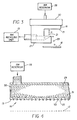
- FIG. 5 is a fragmented view in cross-section of a contaminated print head with schematic representation of misaligned ink drops due to contamination;
- FIG. 6 is a perspective view of a rotating disk cleaning assembly having a rotating disk and shaft for removing contaminant from a print head surface, in accordance with a preferred embodiment of the present invention;
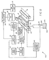
- FIG. 7 is a simplified block schematic diagram of a second embodiment printer system equipped with a page width print head with fixed gutter and rotating disk cleaning assembly disposed adjacent to the print head;
- FIG. 8 is a simplified block schematic diagram of a third embodiment printer equipped with a reciprocating print head with fixed gutter and cleaning mechanism disposed on the same block as print head;
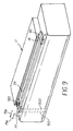
- FIG. 9 shows an isometric view of print head with a rotating disk cleaning assembly aligned for widthwise translation;
- FIG. 10 shows a side view of the rotating disk cleaning assembly of FIG. 9 aligned for widthwise translation;
- FIG. 11 is a simplified block schematic diagram of a fourth embodiment printer system equipped with a modified gutter for facilitating the flow of a cleaning liquid onto the rotating disk; and
- FIG. 12 is a side view of a print head with a modified gutter according to the fourth embodiment printer system shown in FIG. 11.
-
- Numerals and parts in the detailed description correspond to like references in the figures unless otherwise indicated.
- The present description will be directed in particular to elements forming part of, or cooperating more directly with, apparatus in accordance with the present invention. It is to be understood that elements not specifically shown or described may take various forms well known to those skilled in the art.
- Therefore, referring to FIGS. 1A and 1B, therein are shown first and second examples of a first embodiment self-cleaning printer system denoted generally as 400 and 410, respectively, according to the invention. The self-cleaning
printer systems image source 10, such as a scanner or a computer, that provides the raster image data, outline image data in the form of a page description language, or other forms of digital image data. Theimage source 10 is converted to half-toned bitmap image data by an image-processingunit 12, which stores the image data in memory. A plurality ofheater control circuits 14 read the data from memory within the image-processingunit 12 and apply time-varying electrical pulses to a set ofnozzle heaters 50 that are part of aprint head 16. The action of the nozzle heaters 59 andprint head 16 during printing is shown in FIG. 3 wherein the electrical pulses are applied at an appropriate time, and to the appropriate nozzle, so that drops 23 form a continuous ink jet stream to create spots on arecording medium 18, typically paper, in an appropriate position designated by the data in the memory of theimage processing unit 12. Non-deflected ink drops 21 formed in the non-printing area are intercepted by agutter 17, which is fixed in relation to theprint head 16. - Referring to FIGS. 1A and 2B,
recording medium 18 is moved relative to theprint head 16 by a recordingmedium transport system 20, which is electronically controlled by a papertransport control system 22, and which, in turn, is controlled by amicro-controller 24. The papermedium transport system 22 shown in FIGS. 1A and 1B is shown in schematic form only, and many different mechanical configurations are possible, as is known to those of skill in the art. For example, a transfer roller could be used as a papermedium transport system 22 to facilitate transfer of the ink drops 23 torecording medium 18. Such transfer roller technology is well known in the art. In the case of page width print heads, it is most convenient to move therecording medium 18 past a stationary print head. However, in the case of a scanning print system (as shown schematically in FIG. 1B), it is usually most convenient to move the print head along one axis (the sub-scanning direction) and therecording medium 18 along an orthogonal axis (the main scanning direction) in a relative raster motion. - Referring to FIGS. 1A, 1B, 3 and 4, ink is contained in an
ink reservoir 28 under pressure. In the non printing state, continuous ink jet drop streams are unable to reach therecording medium 18 due to the position ofgutter 17 that blocks the stream to allow a portion of the ink to be recycled by anink recycling unit 19. The ink-recycling unit 19 reconditions the ink and feeds it back toink reservoir 28. Such ink recycling units are well known in the art. The ink pressure suitable for optimal operation will depend on a number of factors, including geometry and thermal properties of the nozzles and thermal properties of the ink. A constant ink pressure can be achieved by applying pressure toink reservoir 28 under the control ofink pressure regulator 26. - The ink is distributed to the back surface of the
print head 16 by anink channel device 30 and throughink channel 31, as shown in FIG. 4. The ink preferably flows through slots and/or holes etched through silicon substrate ofprint head 16 to itsprint head surface 15, where a plurality ofnozzles 25 andheaters 50 are situated. FIG. 2 is an isotropic view of theprint head 16 andgutter 17. Withprint head 16 fabricated from silicon, it is possible to integrateheater control circuits 14 with theprint head 16. In operation, non-deflected ink drops 21 are intercepted bygutter 17, while deflected ink drops 23 land on therecording medium 18. Deflection may be caused by a variety of methods including the asymmetric heating method discussed in US Patent Application Serial No. 08/954317 to Chwalek et al. - Turning now to FIG. 5, it has been observed that the
print head surface 15 may become fouled bycontaminant 55.Contaminant 55 may be, for example, an oily film or particulate matter residing on the surface ofprint head surface 15.Contaminant 55 also may partially or completely obstructs one or more of the plurality ofnozzles 25. The particulate matter may be, for example, particles of dirt, dust, metal and/or encrustations of dried ink. The oily film may be, for example, grease or the like. Presence ofcontaminant 55 is undesirable because whencontaminant 55 completely obstructs one or more of the plurality ofnozzles 25, ink is prevented from being ejected fromnozzle 25. In this regard, the terms "nozzle" and "nozzles" are used interchangeably throughout either in the singular or plural as may be appropriate. - In addition, when
contaminant 55 partially obstructsnozzle 25, flight ofink droplets 60 may be diverted fromfirst axis 63 to travel along a second axis 65 (as shown). Ifink droplets 60 travels along second axis 65,ink droplets 60 will land onrecording medium 18 in an unintended location. In this manner, such complete or partial obstruction ofnozzle 25 leads to printing artifacts such as "banding", a highly undesirable result. A similar printing artifact results if non-selected drops 21 travel onthird axis 66. Also, the presence ofcontaminant 55 may alter surface wetting and inhibit proper formation ofdroplets 60. Therefore, it is desirable to clean (i.e., remove)contaminant 55 to avoid these and other printing artifacts. - Therefore, the self-cleaning
printer systems cleaning mechanism 140 that can be used for simultaneously removingcontaminant 55 from theprint head surface 15 of theprint head 16 and thenozzles 25, according to the invention. In particular, the self-cleaningprinter system 400 of FIG. 1A is of the page width print head variety, while self-cleaningprinter system 410 of FIG. 1B illustrates a scanning type print head. The differences between a page width print head and a scanning type print head are well understood by those of ordinary skill. Thecleaning mechanism 140 includes a rotatingdisk cleaning assembly 32, disposed for directingcleaning liquid 300 carried in or on a soft absorbent covering 195 ondisk 190 to surface 15 andnozzles 25.Disk 190 moves along theprint head surface 15 and acrossnozzles 25 to cleancontaminant 55 therefrom.Disk 190 may be constructed of a soft absorbent material such as felt, polyurethane sponge or expanded polytetrafluroethylene so that cleaning liquid supplied to it is absorbed by the soft absorbent covering. During cleaning, cleaning liquid 300 in or on soft absorbent covering 195 provides chemical cleaning and lubrication betweendisk 190 andprint head surface 15. Alternatively,disk 190 may be constructed of a stiff material such as plastic or metal coated with softabsorbent material 195. Thestiff material 193 is perforated to allow cleaning liquid 300 supplied to it to wick through and get absorbed by soft absorbent covering 195. The cleaning liquid 300 mentioned hereinabove may be any suitable liquid solvent composition, such as ink, water, isopropanol, diethylene glycol, diethylene glycol monobutyl ether, octane, acids and bases, surfactant solutions and any combination thereof. Complex liquid compositions may also be used, such as microemulsions, micellar surfactant solutions, vesicles and solid particles dispersed in the cleaningliquid 300. - To better understand the implementation of print
head cleaning assembly 32 and, in particular, thedisk 190, reference is made to FIG. 6. FIG. 6 is a perspective view of a section of rotatingdisk cleaning assembly 32 having adisk 190 and ashaft 191 for removing contaminant from aprint head surface 15, in accordance with a preferred embodiment of the present invention. Thedisk 190 can be constructed by laminating a perforated metal orplastic disk 193 with a softabsorbent material 195.Arrow 604 indicates the motion ofdisk 190 when driven by a motor (not shown) coupled toshaft 191. In first embodiment self-cleaningprinter systems assembly block 180 prior to engagement ofdisk 190 withprint head surface 15. - In operation, upon receiving an electronic signal from
micro-controller 24 via cleaningassembly control 40, pump 36 is activated causing cleaning liquid 300 to be sprayed onto surface ofdisk 190.Cleaning assembly control 40 also activates disk motor (not shown) causing thedisk 190 to rotate.Micro-controller 24 also sends as electronic signal to printhead transport control 42, which causesprint head 16 to assume a "maintenance" position by translating towarddisk 190 following the direction of arrow 44a. Preferably,disk 190 is pre-aligned-withprint head surface 15 ofprint head 16 so that whenprint head 16 reachesdisk 190,print head surface 15 andnozzles 25 are in contact with softabsorbent material 195 ofdisk 190. Thus, asprint head 16 continues to travel along direction of arrow 44a,contaminant 55 onprint head surface 15 and innozzles 25 is removed by thedisk 190. After cleaning,print head 16 is translated back along direction ofarrow 44b to its normal printing position. - As can be appreciated by those of ordinary skill, the process of
engaging disk 190 withprint head surface 15 described above is one of many methods of usingcleaning assembly 32 to cleanprint head surface 15 andnozzles 25. For example rather that havingprint head surface 15 moved towardsdisk 190, cleaningassembly 32 may be optionally equipped with its own translation capability wherein the cleaningassembly 32 moves from a "home" position to a cleaning position that enables thedisk 190 to come into contact with theprint head surface 15. - Referring to FIG. 7, therein is shown an example of self cleaning ink jet printer system, denoted generally as 420 in which
cleaning assembly 32 may be translated for the purpose of cleaningprint head surface 15 andnozzles 25 ofprint head 16. By way of example only, printhead cleaning assembly 32 may be supported on an elevator (not shown) and lifted in direction ofarrow 46b to appropriate location in order to engage thedisk 190 withprint head surface 15 ofprint head 16. This corresponds to the cleaning position of the cleaningassembly 32. Similarly, translation of cleaningassembly 32 alongarrows 70a and 70b may also be utilized to aid optimal engagement ofdisk 190 withprint head surface 15 ofprint head 16. Afterprint head surface 15 andnozzles 25 have been cleaned,print head 16 is translated back to its printing position, and printhead cleaning assembly 32 is lowered to its rest or home position alongarrow 46a. - When required,
disk 190 may be replaced or cleaned.Disk 190 may be cleaned using cleaning liquid supply to cleaningassembly block 180. For example, cleaningliquid 300 may be suctioned from the cleaningliquid reservoir 270 and directed through piping segment 38a and squirted ontodisk 190 during cleaning. Used cleaning liquid can be returned to cleaningliquid reservoir 270 viapiping segment 38b. Alternatively, a mechanism (not shown) may be provided tolower disk 190 so that it is in contact with vacuum slots (not shown) provided in cleaningassembly block 180. Cleaning liquid 300 supplied todisk 190 bypump 36 may now be sucked away byvacuum pump 34. - Referring to FIGS. 8, 9, and 10 therein is shown an example of a third embodiment self cleaning ink jet printer system, denoted generally as 430, in which a print
head cleaning assembly 33 is provided on the same block asprint head 16. In order to cleanprint head surface 15 andnozzles 25,disk 190 translates back and forth onguide rail 77 following arrows75a and 75b. According to the third embodiment ofprinter system 430, rotatingdisk cleaning assembly 33 is mounted onprint head 16 and pre-aligned withsurface 15 andgutter 17. Upon receiving an appropriate electrical signal from cleaningassembly controller 40 andmicro-controller 24, rotatingdisk cleaning assembly 33 is activated to translate along the direction of seventh arrow 75a usingguide rail 77, as shown in FIG. 9. The motor driving the rotatingdisk cleaning assembly 33 is not shown. - As before,
disk 190 is covered with a softabsorbent material 195 and may be cleaned onpad 90.Cleaning liquid 300 is supplied viaduct 500 and recycled throughduct 510. Further more, a separate duct (not shown) may be provided to supply vacuum suction todisk 190 during cleaning. - Referring to FIGS. 11 and 12 therein is shown an example of a fourth embodiment self cleaning ink
jet printer system 440 capable of removingcontaminant 55 fromsurface 15 andnozzles 25. In particular, inkjet printer system 440 has adisk 190 that is supplied with cleaning liquid 300 through modified gutter 17a.Cleaning liquid 300 is pumped to modified gutter 17a throughvalve 520 andpiping segment 530 bypump 36. To facilitate the flow of cleaning liquid, modified gutter 17a has aninternal duct 85, which delivers cleaning liquid 300 onto a soft absorbent covering 195 on thedisk 190. Delivery of cleaning liquid through modified gutter 17a is compatible with previously discussed self cleaning printer systems, i.e., modified gutter 17a,valve 520 andpiping segment 530 may readily be added to self cleaningprinter systems - While the invention has been described with particular reference to its preferred embodiments, it will be understood by those skilled in the art that various changes may be made and equivalents may be substituted for elements of the preferred embodiments without departing from the invention. For example, it will be appreciated that FIGS. 7, 8, 9, and 11 depict a page width print head by way of example only. Scanning type print heads that are smaller than page width size can also be cleaned using a variation of the method described above. In yet another variation, rather that use a cleaning
liquid 300 for cleaningprint head surface 15 andnozzles 25 ofprint head 16,ink 29 may be squirted out ofnozzles 25 on to soft absorbent covering 195 ondisk 190 during cleaning. At the end of the cleaning cycle,disk 190 and soft absorbent covering 195 may be cleaned with cleaning liquid 300 by the methods described above. In yet another variation, cleaningassemblies print head surface 15 andnozzles 25. In addition, many modifications may be made to adapt a particular situation and material to a teaching of the present invention without departing from the essential teachings of the invention.
Claims (10)
- A self-cleaning ink jet printer system, comprising:a print head (16) having a surface (15) thereon;an ink reservoir (28) containing ink (29);a gutter (17) integrally connected to said print head (16) for intercepting said ink (29) in a non-printing mode characterized by,a rotating disk cleaning assembly (32) for cleaning said print head surface.
- The ink jet printer system of claim 1, wherein said rotating disk cleaning assembly (32) comprises:a disk (190);a shaft (191) having an internal rotating member, said internal rotating member of said shaft connected to said disk for coming into direct rotating sliding contact with said print head surface to thereby remove contaminants from said print head surface; anda motor for driving said shaft.
- The ink jet printer of system of claim 2, further comprising an absorbent covering (195) surrounding said disk.
- The ink jet printer system of claim 1, further comprising:a reservoir (270) for storing a cleaning liquid;a first piping segment (38a) providing a flow channel in a first direction between said reservoir and said rotating disk cleaning assembly (32); anda pump for directing a cleaning liquid from said reservoir to said rotating disk cleaning assembly (32) via said first piping segment (38a).
- The ink jet printed system of claim 4, further comprising a second piping segment (38b) providing a flow channel in a second direction between said reservoir and said rotating disk cleaning assembly (38b) so that used cleaning liquid is returned to said cleaning reservoir.
- The ink jet printer system of claim 2, further comprising a cleaning assembly control (40) configured to cause said rotating disk cleaning assembly (32) to assume a cleaning position, said cleaning assembly control being configured to cause said rotating disk cleaning assembly (32) to assume a normal printing position after cleaning of said printer head surface.
- The ink jet printer system of claim 2, further comprising a micro-controller (24) configured to send an electronic signal that causes said print head (16) to assume a maintenance position wherein said print head surface is translated towards said rotating disk cleaning assembly (32).
- The ink jet printer system of claim 2, further comprising a block (33) supporting said print head (16) and wherein said rotating disk cleaning assembly (32) is mounted on said block adjacent said print head (16).
- The ink jet printer system of claim 8, further comprising a guide rail (77) configured to permit said disk to translate along an areas spanned by said print head surface.
- The ink jet printer system of claim 2, wherein said rotating disk cleaning assembly (32) is mounted on said print head (16) and pre-aligned with said print head surface.
Applications Claiming Priority (2)
| Application Number | Priority Date | Filing Date | Title |
|---|---|---|---|
| US09/619,999 US6554391B1 (en) | 2000-07-20 | 2000-07-20 | Rotating disk cleaning assembly apparatus and method for an ink jet print head with fixed gutter |
| US619999 | 2000-07-20 |
Publications (1)
| Publication Number | Publication Date |
|---|---|
| EP1174270A1 true EP1174270A1 (en) | 2002-01-23 |
Family
ID=24484169
Family Applications (1)
| Application Number | Title | Priority Date | Filing Date |
|---|---|---|---|
| EP01202523A Withdrawn EP1174270A1 (en) | 2000-07-20 | 2001-07-02 | Rotating disk cleaning assembly apparatus and method for an inkjet print head with fixed gutter |
Country Status (3)
| Country | Link |
|---|---|
| US (1) | US6554391B1 (en) |
| EP (1) | EP1174270A1 (en) |
| JP (1) | JP2002036575A (en) |
Families Citing this family (9)
| Publication number | Priority date | Publication date | Assignee | Title |
|---|---|---|---|---|
| JP4058969B2 (en) * | 2002-03-15 | 2008-03-12 | セイコーエプソン株式会社 | Film forming apparatus, head cleaning method, device manufacturing apparatus and device |
| US7128823B2 (en) | 2002-07-24 | 2006-10-31 | Applied Materials, Inc. | Anolyte for copper plating |
| US7247222B2 (en) * | 2002-07-24 | 2007-07-24 | Applied Materials, Inc. | Electrochemical processing cell |
| JP4389443B2 (en) * | 2002-12-20 | 2009-12-24 | セイコーエプソン株式会社 | Wiping unit for inkjet head, liquid droplet ejection apparatus including the same, and method for manufacturing electro-optical device |
| US20050035991A1 (en) * | 2003-08-12 | 2005-02-17 | Fredrickson Daniel John | Inkjet printer cleaning system and method |
| US20050125928A1 (en) * | 2003-12-16 | 2005-06-16 | Pitney Bowes Inc. | Optical sensor cleaner |
| US7895378B2 (en) | 2004-04-27 | 2011-02-22 | Apple Inc. | Method and system for allowing a media player to transfer digital audio to an accessory |
| KR100651919B1 (en) * | 2005-09-29 | 2006-12-01 | 엘지전자 주식회사 | Mobile communication terminal with recording speed control function and method using the same |
| JP5438632B2 (en) * | 2010-08-31 | 2014-03-12 | 富士フイルム株式会社 | Droplet discharge device |
Citations (2)
| Publication number | Priority date | Publication date | Assignee | Title |
|---|---|---|---|---|
| JPS6322656A (en) * | 1986-07-01 | 1988-01-30 | Yokogawa Hewlett Packard Ltd | Ink jet printer |
| EP0988978A1 (en) * | 1998-09-24 | 2000-03-29 | EASTMAN KODAK COMPANY (a New Jersey corporation) | Cleaning of orifices in an ink jet printing apparatus |
Family Cites Families (11)
| Publication number | Priority date | Publication date | Assignee | Title |
|---|---|---|---|---|
| US4401990A (en) * | 1980-08-28 | 1983-08-30 | Sharp Kabushiki Kaisha | Nozzle cleaning device in an ink jet system printer |
| DE3042997A1 (en) * | 1980-11-14 | 1982-07-01 | Olympia Werke Ag, 2940 Wilhelmshaven | Typing head nozzle ink collector - has moistened surface placed against edge between nozzle face and underside |
| JPS5914964A (en) * | 1982-07-15 | 1984-01-25 | Seiko Epson Corp | inkjet printer |
| IT1195151B (en) | 1986-09-05 | 1988-10-12 | Olivetti & Co Spa | Operation restoring appts. for ink jet printing nozzle |
| US4933015A (en) * | 1987-04-02 | 1990-06-12 | Charles D. Knapp | Method of cleaning type elements and print heads |
| US4829318A (en) | 1987-09-30 | 1989-05-09 | Dataproducts, Inc. | Head tending system for purging and cleaning an ink jet print head |
| US4968994A (en) | 1987-10-23 | 1990-11-06 | Howtek, Inc. | Head tending apparatus for an ink jet printer |
| US5103244A (en) * | 1990-07-05 | 1992-04-07 | Hewlett-Packard Company | Method and apparatus for cleaning ink-jet printheads |
| US5614930A (en) | 1994-03-25 | 1997-03-25 | Hewlett-Packard Company | Orthogonal rotary wiping system for inkjet printheads |
| US5574485A (en) * | 1994-10-13 | 1996-11-12 | Xerox Corporation | Ultrasonic liquid wiper for ink jet printhead maintenance |
| US5914734A (en) | 1996-11-13 | 1999-06-22 | Hewlett-Packard Company | Printhead servicing system and method using a moveable wiper between a fluid source and a printhead |
-
2000
- 2000-07-20 US US09/619,999 patent/US6554391B1/en not_active Expired - Fee Related
-
2001
- 2001-07-02 EP EP01202523A patent/EP1174270A1/en not_active Withdrawn
- 2001-07-23 JP JP2001221324A patent/JP2002036575A/en active Pending
Patent Citations (2)
| Publication number | Priority date | Publication date | Assignee | Title |
|---|---|---|---|---|
| JPS6322656A (en) * | 1986-07-01 | 1988-01-30 | Yokogawa Hewlett Packard Ltd | Ink jet printer |
| EP0988978A1 (en) * | 1998-09-24 | 2000-03-29 | EASTMAN KODAK COMPANY (a New Jersey corporation) | Cleaning of orifices in an ink jet printing apparatus |
Non-Patent Citations (1)
| Title |
|---|
| PATENT ABSTRACTS OF JAPAN vol. 012, no. 227 (M - 713) 28 June 1988 (1988-06-28) * |
Also Published As
| Publication number | Publication date |
|---|---|
| US6554391B1 (en) | 2003-04-29 |
| JP2002036575A (en) | 2002-02-05 |
Similar Documents
| Publication | Publication Date | Title |
|---|---|---|
| EP1108546B1 (en) | An apparatus and methods for a wiper edge cleaner for ink jet print head with fixed gutter | |
| US6164751A (en) | Ink jet printer with wiper blade and vacuum canopy cleaning mechanism and method of assembling the printer | |
| US6435647B2 (en) | Ink jet printer with cleaning mechanism and method of assembling same | |
| EP1060894B1 (en) | Multi-fluidic cleaning for ink jet print heads | |
| US6241337B1 (en) | Ink jet printer with cleaning mechanism having a wiper blade and transducer and method of assembling the printer | |
| US6406122B1 (en) | Method and cleaning assembly for cleaning an ink jet print head in a self-cleaning ink jet printer system | |
| KR100408354B1 (en) | Inkjet printhead inspection service method and inkjet printhead inspection service station for repair | |
| US6511151B1 (en) | Ink jet printer and cleaning blade and method of cleaning | |
| US6283575B1 (en) | Ink printing head with gutter cleaning structure and method of assembling the printer | |
| US6367905B1 (en) | Print head cleaning assembly with roller and method for an ink jet print head with fixed gutter | |
| US6497472B2 (en) | Self-cleaning ink jet printer and print head with cleaning fluid flow system | |
| US6585348B2 (en) | Inkjet printer cartridge adapted for enhanced cleaning thereof and method of assembling the printer cartridge | |
| US6789873B2 (en) | Inkjet printer with nozzle maintenance system relocated by media carrier | |
| EP0914953B1 (en) | Electrical interconnect cleaning system for inkjet cartridges | |
| US6663218B2 (en) | Head recovery device, head recovery method and ink jet recording apparatus | |
| US6554391B1 (en) | Rotating disk cleaning assembly apparatus and method for an ink jet print head with fixed gutter | |
| US6523930B2 (en) | Ink jet printer with cleaning mechanism using laminated polyimide structure and method cleaning an ink jet printer | |
| JP2001219565A (en) | Ink jet recording device | |
| JPH07246709A (en) | Inkjet recording device | |
| JPH07205436A (en) | Inkjet recording device |
Legal Events
| Date | Code | Title | Description |
|---|---|---|---|
| PUAI | Public reference made under article 153(3) epc to a published international application that has entered the european phase |
Free format text: ORIGINAL CODE: 0009012 |
|
| AK | Designated contracting states |
Kind code of ref document: A1 Designated state(s): DE FR GB Kind code of ref document: A1 Designated state(s): AT BE CH CY DE DK ES FI FR GB GR IE IT LI LU MC NL PT SE TR |
|
| AX | Request for extension of the european patent |
Free format text: AL;LT;LV;MK;RO;SI |
|
| 17P | Request for examination filed |
Effective date: 20020606 |
|
| AKX | Designation fees paid |
Free format text: DE FR GB |
|
| 17Q | First examination report despatched |
Effective date: 20041118 |
|
| GRAP | Despatch of communication of intention to grant a patent |
Free format text: ORIGINAL CODE: EPIDOSNIGR1 |
|
| STAA | Information on the status of an ep patent application or granted ep patent |
Free format text: STATUS: THE APPLICATION IS DEEMED TO BE WITHDRAWN |
|
| 18D | Application deemed to be withdrawn |
Effective date: 20060325 |