EP1172917A2 - Spindle Motor - Google Patents
Spindle Motor Download PDFInfo
- Publication number
- EP1172917A2 EP1172917A2 EP01116382A EP01116382A EP1172917A2 EP 1172917 A2 EP1172917 A2 EP 1172917A2 EP 01116382 A EP01116382 A EP 01116382A EP 01116382 A EP01116382 A EP 01116382A EP 1172917 A2 EP1172917 A2 EP 1172917A2
- Authority
- EP
- European Patent Office
- Prior art keywords
- flange
- stator
- shaft
- rotor
- magnet
- Prior art date
- Legal status (The legal status is an assumption and is not a legal conclusion. Google has not performed a legal analysis and makes no representation as to the accuracy of the status listed.)
- Withdrawn
Links
Images
Classifications
-
- F—MECHANICAL ENGINEERING; LIGHTING; HEATING; WEAPONS; BLASTING
- F16—ENGINEERING ELEMENTS AND UNITS; GENERAL MEASURES FOR PRODUCING AND MAINTAINING EFFECTIVE FUNCTIONING OF MACHINES OR INSTALLATIONS; THERMAL INSULATION IN GENERAL
- F16C—SHAFTS; FLEXIBLE SHAFTS; ELEMENTS OR CRANKSHAFT MECHANISMS; ROTARY BODIES OTHER THAN GEARING ELEMENTS; BEARINGS
- F16C27/00—Elastic or yielding bearings or bearing supports, for exclusively rotary movement
- F16C27/04—Ball or roller bearings, e.g. with resilient rolling bodies
-
- H—ELECTRICITY
- H02—GENERATION; CONVERSION OR DISTRIBUTION OF ELECTRIC POWER
- H02K—DYNAMO-ELECTRIC MACHINES
- H02K1/00—Details of the magnetic circuit
- H02K1/06—Details of the magnetic circuit characterised by the shape, form or construction
- H02K1/12—Stationary parts of the magnetic circuit
- H02K1/18—Means for mounting or fastening magnetic stationary parts on to, or to, the stator structures
- H02K1/187—Means for mounting or fastening magnetic stationary parts on to, or to, the stator structures to inner stators
-
- H—ELECTRICITY
- H02—GENERATION; CONVERSION OR DISTRIBUTION OF ELECTRIC POWER
- H02K—DYNAMO-ELECTRIC MACHINES
- H02K5/00—Casings; Enclosures; Supports
- H02K5/24—Casings; Enclosures; Supports specially adapted for suppression or reduction of noise or vibrations
Definitions
- the present invention relates to a spindle motor employed for rotating and driving a disk or the like.
- a motor of such a type that a stator is supported and fixed to a flange on which a shaft is fixedly supported and a rotor provided with a magnet in its inner periphery is rotatably supported by the shaft while the magnet is opposed with a predetermined interval to the outer periphery of the stator.
- the rotor rotates on the outer periphery of the stator in accordance with the interaction between magnetic flux generated from a coil provided in the stator and magnetic flux generated from the magnet.
- this spindle motor is particularly suitable to a motor for rotating and driving a disk storage medium such as a magnetic disk used as a storage medium of a computer.
- stator comes into direct contact with the flange and is fixedly supported to the flange, electromagnetic vibration and vibration caused from a rotating action which are generated in the stator by an alternating current supplied to the coil (stator coil) of the stator are directly transmitted to the flange.
- the shaft comes into direct contact with the flange and is supported by and fixed to the flange, the vibration due to the rotation of the rotor which the shaft receives (rotating vibration) is, inconveniently, transmitted directly to the flange as it is.
- the electromagnetic vibration and the vibration caused from the rotating action from the stator and the rotating vibration from the shaft are both transmitted to the flange as they are, so that the vibration is doubled. Further, a larger vibration is sometimes generated due to the interaction of both the vibrations, or due to resonance with the flange or the like, which undesirably causes generation of noise.
- the present invention was made in order to solve the problems of the above-mentioned prior art and it is an object of the present invention to provide a spindle motor in which the transmission of electromagnetic vibration and vibration caused from a rotating action from a stator or rotating vibration from a shaft to a flange can be suppressed and the generation of vibration, especially, the generation of large vibration or noise in the flange, can be prevented.
- a spindle motor comprising: a flange for supporting and fixing a shaft; a stator supported by and fixed to the flange; and a rotor provided with a magnet in its inner periphery, the rotor being rotatably supported by the shaft in a condition where the magnet is opposed with a predetermined interval to the outer periphery of the stator, the rotor rotating in accordance with the interaction between magnetic flux from a coil provided in the stator and magnetic flux from the magnet, characterized in that a damping member is interposed between the flange and the stator.
- a spindle motor comprising: a flange for supporting and fixing a shaft; a stator supported by and fixed to the flange; and a rotor provided with a magnet in its inner periphery, the rotor being rotatably supported by the shaft in a condition where the magnet is opposed with a predetermined interval to the outer periphery of the stator, the rotor rotating in accordance with the interaction between magnetic flux from a coil provided in the stator and magnetic flux from the magnet, characterized in that a damping member is interposed between the flange and the shaft.
- a spindle motor comprising: a flange for supporting and fixing a shaft; a stator supported by and fixed to the flange; and a rotor provided with a magnet in its inner periphery, the rotor being rotatably supported by the shaft in a condition where the magnet is opposed with a predetermined interval to the outer periphery of the stator, the rotor rotating in accordance with the interaction between magnetic flux from a coil provided in the stator and magnetic flux from the magnet, characterized in that each of the shaft and the stator comes into direct contact with the flange and is supported by and fixed to the flange, and in that at least portions of the flange which are in contact with the shaft and the stator, respectively, are formed of damping material.
- the spindle motor of the first, the second, or the third aspect of the present invention is characterized in that the rotor can be loaded with a disk storage medium, and the spindle motor is configured in such a manner as to rotate and drive a disk.
- the damping member is interposed between the flange and the stator, so that the electromagnetic vibration and the vibration caused from a rotating action which are generated on the stator due to an alternating current supplied to the coil of the stator (stator coil) can be damped and absorbed by the damping member and can be prevented from being transmitted to the flange.
- the damping member is interposed between the flange and the shaft, the rotating vibration of the rotor which the shaft receives is damped and absorbed by the damping member and can be prevented from being transmitted to the flange.
- At least portions of the flange which are in contact with the shaft and the stator, respectively, are formed of damping material.
- the shaft and the stator are merely mounted on the flange without taking a trouble to interpose the damping members respectively between the flange and the shaft, and between the flange and the stator, thereby obtaining the same effect as those provided by the first and second aspects of the present invention.
- the disk storage medium can be mounted on the rotor so that the spindle motor of the present invention is configured as a motor for rotating and driving a disk.
- a motor for rotating and driving the disk storage medium provided with a characteristic that the vibration from the stator or the rotor is damped and absorbed by the damping members or portions formed of damping material as well as a characteristic of small unevenness in rotation which is originally included in the outer rotor type spindle motor.
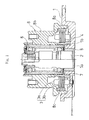
- Fig. 1 is a longitudinal sectional view of one embodiment of a spindle motor according to the present invention.
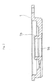
- the numeral 1 designates a flange serving as a motor base. To the flange 1, each of a shaft 2 and a stator 3 is fixed.
- the flange 1 is formed substantially in the shape of a tray.
- a shaft support hole 1a is opened on the substantially central portion of the flange 1.
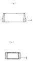
- the stator 3 is supported by and fixed to the outer periphery of the support portion 1b in the peripheral edge of the shaft support hole 1a opened on the flange 1 through a substantially cylindrical first bush 4 (see Fig. 3).
- the first bush 4 is initially fitted to the outer periphery of the support portion 1b, then, the stator 3 is fitted and fixed to the outer periphery (the outer periphery of an upper end side with a slightly small diameter) of the first bush 4, so that the stator 3 is supported by and fixed to the flange 1.
- This stator 3 mainly comprises a coil (stator coil) 3a and a core (stator core) 3b.
- the above-mentioned shaft 2 is supported and fixed into the shaft support hole 1a opened on the flange 1 through a cylindrical second bush 5 (see Fig. 4).
- the second bush 5 is initially fitted to the inner periphery of the shaft support hole 1a and then, the shaft 2 is fitted and inserted into the second bush 5 from an upper side in the drawing, so that the shaft 2 is supported by and fixed to the flange 1.
- Both the first bush 4 and the second bush 5 are made of a damping material and constitutes damping members.
- the damping material employed here for example, there is exemplified "D2052" alloy (alloy comprising Mn and Cu as main components) produced by Daido Co., Ltd.
- a rotor 8 is rotatably attached through bearings 6 and 7 arranged in two positions with a predetermined interval in the axial direction of the shaft.
- the bearings 6 and 7 used here while the outer rings of the bearings 6 and 7 are commonly formed, the inner ring of the bearing 6 is independent and the inner ring of the bearing 7 is formed integrally with the shaft 2.
- the bearings (not shown) whose inner rings and outer rings are both independent may be employed.
- the lower end portion 8a of the rotor 8 in Fig. 1 is coaxially expanded more outward than an intermediate portion 8b, and a ring shaped permanent magnet 8c opposed with a predetermined interval to the stator core 3b is fixed to the inner periphery of the lower end portion 8a.
- the motor of the present invention is employed as a motor for rotating and driving a disk storage medium such as a magnetic disk, an optical disk or a photomagnetic disk
- the desired number of disks are mounted on the outer periphery of the intermediate portion 8b.
- a plurality of disks are mounted on the intermediate portion 8b of the rotor, they are laminated and mounted axially in the outer periphery direction of the intermediate portion 8b.
- the rotor 8 rotates in accordance with the interaction between magnetic flux from the stator coil 3a and magnetic flux from the permanent magnet 8c.
- the generation of vibration or noise of the flange 1 due to the electromagnetic vibration and the vibration caused from a rotating action from the stator 3 and the rotating vibration from the shaft 2 can be prevented by the bushes 4 and 5 of damping members that are separate from the flange 1, it should be noted that the flange 1 itself may be formed of damping material. Further, only portions of the flange 1 which are in contact with the shaft 2 and the stator 3, respectively, may be formed of damping material.
- damping member or damping material used in the motor of the present invention is not limited to that employed in the above embodiment.
- the motor according to the present invention is also suitable for a scanner motor and so on, in addition to the motor for rotating and driving a disk storage medium.
- the electromagnetic vibration and the vibration caused from a rotating action from the stator or the rotating vibration from the shaft are damped and absorbed by the damping members, the generation of vibration in the flange, especially, the generation of large vibration or noise can be effectively prevented.
- the motor of the present invention allows a disk storage medium to be mounted on the rotor, and the spindle motor is formed for rotating and driving a disk
- the motor for rotating and driving the disk storage medium can be obtained, in which no vibration or noise is generated in the flange, because the vibration from the stator or the rotor is damped and absorbed by the damping member.
Landscapes
- Engineering & Computer Science (AREA)
- Power Engineering (AREA)
- General Engineering & Computer Science (AREA)
- Mechanical Engineering (AREA)
- Motor Or Generator Frames (AREA)
- Permanent Magnet Type Synchronous Machine (AREA)
- Iron Core Of Rotating Electric Machines (AREA)
- Rotational Drive Of Disk (AREA)
- Connection Of Motors, Electrical Generators, Mechanical Devices, And The Like (AREA)
Abstract
Description
Claims (4)
- A spindle motor comprising: a flange for supporting and fixing a shaft; a stator supported by and fixed to said flange; and a rotor provided with a magnet in its inner periphery, said rotor being rotatably supported by said shaft in a condition where said magnet is opposed with a predetermined interval to the outer periphery of said stator, said rotor rotating in accordance with the interaction between magnetic flux from a coil provided in said stator and magnetic flux from said magnet, characterizedin that
a damping member is interposed between said flange and said stator. - A spindle motor comprising: a flange for supporting and fixing a shaft; a stator supported by and fixed to said flange; and a rotor provided with a magnet in its inner periphery, said rotor being rotatably supported by said shaft in a condition where said magnet is opposed with a predetermined interval to the outer periphery of said stator, said rotor rotating in accordance with the interaction between magnetic flux from a coil provided in said stator and magnetic flux from said magnet, characterized in that
a damping member is interposed between said flange and said shaft. - A spindle motor comprising: a flange for supporting and fixing a shaft; a stator supported by and fixed to said flange; and a rotor provided with a magnet in its inner periphery, said rotor being rotatably supported by said shaft in a condition where said magnet is opposed with a predetermined interval to the outer periphery of said stator, said rotor rotating in accordance with the interaction between magnetic flux from a coil provided in said stator and magnetic flux from said magnet, characterized in thateach of said shaft and said stator comes into direct contact with said flange and is supported by and fixed to said flange, and in thatat least portions of said flange which are in contact with said shaft and said stator, respectively, are formed of damping material.
- The spindle motor according to claim 1, 2 or 3, wherein said rotor can be loaded with a disk storage medium and said spindle motor is configured in such a manner as to rotate and drive a disk.
Applications Claiming Priority (2)
| Application Number | Priority Date | Filing Date | Title |
|---|---|---|---|
| JP2000212706 | 2000-07-13 | ||
| JP2000212706A JP2002034201A (en) | 2000-07-13 | 2000-07-13 | Spindle motor |
Publications (2)
| Publication Number | Publication Date |
|---|---|
| EP1172917A2 true EP1172917A2 (en) | 2002-01-16 |
| EP1172917A3 EP1172917A3 (en) | 2004-12-22 |
Family
ID=18708584
Family Applications (1)
| Application Number | Title | Priority Date | Filing Date |
|---|---|---|---|
| EP01116382A Withdrawn EP1172917A3 (en) | 2000-07-13 | 2001-07-06 | Spindle Motor |
Country Status (3)
| Country | Link |
|---|---|
| US (1) | US6826010B2 (en) |
| EP (1) | EP1172917A3 (en) |
| JP (1) | JP2002034201A (en) |
Cited By (2)
| Publication number | Priority date | Publication date | Assignee | Title |
|---|---|---|---|---|
| DE10237203A1 (en) * | 2002-08-14 | 2004-02-26 | Deere & Company, Moline | transverse flux |
| EP3068018A1 (en) * | 2015-03-12 | 2016-09-14 | Honda Motor Co., Ltd. | Outer rotor motor |
Families Citing this family (6)
| Publication number | Priority date | Publication date | Assignee | Title |
|---|---|---|---|---|
| CN1306684C (en) * | 2003-11-07 | 2007-03-21 | 日本电产株式会社 | Spindle motor and recording disc drive therewith |
| JP4617860B2 (en) * | 2004-12-09 | 2011-01-26 | 株式会社明電舎 | Test equipment for vehicle parts and engines |
| JP2006185484A (en) * | 2004-12-27 | 2006-07-13 | Hitachi Global Storage Technologies Netherlands Bv | Bearing mechanism for head of magnetic disk device and magnetic disk device having the same |
| US7436625B1 (en) * | 2005-01-11 | 2008-10-14 | Western Digital Technologies, Inc. | Disk drive spindle motor having a cavity defined by one of an upper surface of a stator support structure and a lower surface of a stator tooth |
| KR100774889B1 (en) * | 2005-07-16 | 2007-11-08 | 엘지이노텍 주식회사 | Spindle motor |
| JP5081005B2 (en) * | 2007-03-09 | 2012-11-21 | アスモ株式会社 | Brushless motor and manufacturing method thereof |
Family Cites Families (9)
| Publication number | Priority date | Publication date | Assignee | Title |
|---|---|---|---|---|
| DE3347360C2 (en) * | 1983-12-28 | 1995-04-13 | Papst Motoren Gmbh & Co Kg | Brushless external rotor DC motor |
| US4760299A (en) * | 1987-06-11 | 1988-07-26 | The Singer Company | Distortion free synchro |
| US5365388A (en) * | 1991-09-13 | 1994-11-15 | Iomega Corporation | Disk drive constructed to isolate motor vibration |
| JPH06139675A (en) * | 1992-10-27 | 1994-05-20 | Hitachi Ltd | Drive device for disk storage medium |
| US5376850A (en) * | 1993-07-02 | 1994-12-27 | Seagate Technology, Inc. | Audible noise reduction in a disc drive |
| US5481144A (en) * | 1994-06-03 | 1996-01-02 | Seagate Technology, Inc. | Wire guide and adhesive retaining ring for disc drive spindle motor |
| JP3282406B2 (en) * | 1994-09-30 | 2002-05-13 | 富士通株式会社 | Rotary drive device and storage device |
| JP2002533051A (en) * | 1998-12-14 | 2002-10-02 | ビーイーアイ、キムコ・マグネティクス・ディビジョン | Apparatus and method for noise and vibration reduction in electromotive devices |
| WO2001045233A1 (en) * | 1999-12-17 | 2001-06-21 | Encap Motor Corporation | Spindle motor with encapsulated stator and method of making same |
-
2000
- 2000-07-13 JP JP2000212706A patent/JP2002034201A/en not_active Abandoned
-
2001
- 2001-06-29 US US09/893,405 patent/US6826010B2/en not_active Expired - Fee Related
- 2001-07-06 EP EP01116382A patent/EP1172917A3/en not_active Withdrawn
Cited By (3)
| Publication number | Priority date | Publication date | Assignee | Title |
|---|---|---|---|---|
| DE10237203A1 (en) * | 2002-08-14 | 2004-02-26 | Deere & Company, Moline | transverse flux |
| EP3068018A1 (en) * | 2015-03-12 | 2016-09-14 | Honda Motor Co., Ltd. | Outer rotor motor |
| US10193411B2 (en) | 2015-03-12 | 2019-01-29 | Honda Motor Co., Ltd. | Outer rotor motor |
Also Published As
| Publication number | Publication date |
|---|---|
| US20020006012A1 (en) | 2002-01-17 |
| US6826010B2 (en) | 2004-11-30 |
| EP1172917A3 (en) | 2004-12-22 |
| JP2002034201A (en) | 2002-01-31 |
Similar Documents
| Publication | Publication Date | Title |
|---|---|---|
| US4943748A (en) | Motor with cup-shaped rotor having cylindrical portions of different diameter | |
| US6700260B2 (en) | Rotor structure of motor | |
| EP1750352A2 (en) | Spindle motor and disk drive unit | |
| US6826010B2 (en) | Spindle motor | |
| JP3502266B2 (en) | Drive motor for recording medium | |
| EP0613134A1 (en) | Magnetic disk unit | |
| US5475274A (en) | Driving motor | |
| US6469410B2 (en) | Spindle motor for driving disc | |
| US6133660A (en) | Bearing structure for brushless DC motor | |
| US7552453B2 (en) | Disk driving apparatus | |
| JP2002034201A5 (en) | ||
| JP3079536B2 (en) | Spindle motor vibration prevention structure | |
| JP2992862B2 (en) | Motor device | |
| KR100585121B1 (en) | Spindle Motor for Disc Drive | |
| JP2002281712A (en) | Disc driving motor | |
| JP2005192385A (en) | Spindle motor | |
| JP3558704B2 (en) | Spindle motor | |
| JP2005020857A (en) | Stepping motor | |
| JP3026117B2 (en) | Rotating machine | |
| JP2566616Y2 (en) | Rotary cylinder device | |
| JP4232224B2 (en) | PM stepping motor | |
| JPH07231634A (en) | Radial gap spindle motor | |
| JPH11103558A (en) | Automatic balancing apparatus of motor | |
| JPH11113209A (en) | Bearing structure of small-sized motor | |
| JPH10177762A (en) | Spindle mechanism |
Legal Events
| Date | Code | Title | Description |
|---|---|---|---|
| PUAI | Public reference made under article 153(3) epc to a published international application that has entered the european phase |
Free format text: ORIGINAL CODE: 0009012 |
|
| AK | Designated contracting states |
Kind code of ref document: A2 Designated state(s): AT BE CH CY DE DK ES FI FR GB GR IE IT LI LU MC NL PT SE TR |
|
| AX | Request for extension of the european patent |
Free format text: AL;LT;LV;MK;RO;SI |
|
| PUAL | Search report despatched |
Free format text: ORIGINAL CODE: 0009013 |
|
| AK | Designated contracting states |
Kind code of ref document: A3 Designated state(s): AT BE CH CY DE DK ES FI FR GB GR IE IT LI LU MC NL PT SE TR |
|
| AX | Request for extension of the european patent |
Extension state: AL LT LV MK RO SI |
|
| 17P | Request for examination filed |
Effective date: 20050604 |
|
| AKX | Designation fees paid |
Designated state(s): DE GB |
|
| 17Q | First examination report despatched |
Effective date: 20080424 |
|
| STAA | Information on the status of an ep patent application or granted ep patent |
Free format text: STATUS: THE APPLICATION IS DEEMED TO BE WITHDRAWN |
|
| 18D | Application deemed to be withdrawn |
Effective date: 20080905 |