EP1172904A2 - A temporary rotation clamping mechanism for a cable reel - Google Patents
A temporary rotation clamping mechanism for a cable reel Download PDFInfo
- Publication number
- EP1172904A2 EP1172904A2 EP01115208A EP01115208A EP1172904A2 EP 1172904 A2 EP1172904 A2 EP 1172904A2 EP 01115208 A EP01115208 A EP 01115208A EP 01115208 A EP01115208 A EP 01115208A EP 1172904 A2 EP1172904 A2 EP 1172904A2
- Authority
- EP
- European Patent Office
- Prior art keywords
- piece
- rotation clamping
- rotor
- lateral
- lateral piece
- Prior art date
- Legal status (The legal status is an assumption and is not a legal conclusion. Google has not performed a legal analysis and makes no representation as to the accuracy of the status listed.)
- Withdrawn
Links
Images




Classifications
-
- B—PERFORMING OPERATIONS; TRANSPORTING
- B60—VEHICLES IN GENERAL
- B60R—VEHICLES, VEHICLE FITTINGS, OR VEHICLE PARTS, NOT OTHERWISE PROVIDED FOR
- B60R16/00—Electric or fluid circuits specially adapted for vehicles and not otherwise provided for; Arrangement of elements of electric or fluid circuits specially adapted for vehicles and not otherwise provided for
- B60R16/02—Electric or fluid circuits specially adapted for vehicles and not otherwise provided for; Arrangement of elements of electric or fluid circuits specially adapted for vehicles and not otherwise provided for electric constitutive elements
- B60R16/023—Electric or fluid circuits specially adapted for vehicles and not otherwise provided for; Arrangement of elements of electric or fluid circuits specially adapted for vehicles and not otherwise provided for electric constitutive elements for transmission of signals between vehicle parts or subsystems
- B60R16/027—Electric or fluid circuits specially adapted for vehicles and not otherwise provided for; Arrangement of elements of electric or fluid circuits specially adapted for vehicles and not otherwise provided for electric constitutive elements for transmission of signals between vehicle parts or subsystems between relatively movable parts of the vehicle, e.g. between steering wheel and column
-
- H—ELECTRICITY
- H01—ELECTRIC ELEMENTS
- H01R—ELECTRICALLY-CONDUCTIVE CONNECTIONS; STRUCTURAL ASSOCIATIONS OF A PLURALITY OF MUTUALLY-INSULATED ELECTRICAL CONNECTING ELEMENTS; COUPLING DEVICES; CURRENT COLLECTORS
- H01R35/00—Flexible or turnable line connectors, i.e. the rotation angle being limited
- H01R35/02—Flexible line connectors without frictional contact members
- H01R35/025—Flexible line connectors without frictional contact members having a flexible conductor wound around a rotation axis
Definitions
- the present invention relates to a temporary clamp mechanism in a cable reel mounted on a steering apparatus of vehicles.
- the present invention also relates to a temporary clamp mechanism that eliminates the need to provide a steering wheel with a pullout clamp hole under the condition where a rotor of a cable reel is fastened to a steering column with the cable reel temporarily clamped to a stator through a rotation clamping member and the rotation clamping member, which has temporarily stopped the rotation of a rotor, are pulled out after assembling a steering wheel over the stator and rotor.
- a known temporary rotation clamping mechanism for a cable reel is shown in Fig.6 from, for example, Japanese Unexamined Patent Publication No. 2000-48925.
- the cable reel 51 is mounted on a steering apparatus of a vehicle for electrically connecting circuits of a vehicle body with electrical devices (a horn switch, an air bag, etc.)
- a stator 52 fastened to a steering column and a rotor 53 fastened to a steering wheel (hereafter abbreviated as a wheel) side are constructed so that they relatively rotate.
- a flat cable 55 is housed in a wound condition and the flat cable 55 is wound up of wound out in accordance with the direction of rotation of the rotor 53 which follows the wheel rotation.
- the stator 52 and the rotor 53 are positioned in a predetermined rotation phase, and side, generally T-shaped, rotation clamping members 56 are temporarily placed over the stator 52 and the rotor 53 from an upper position so that the stator 52 and the rotor 53 cannot rotate in order to maintain the predetermined rotation phase. That is, a lateral piece 57 of the rotation clamping member 56 is fixed to an upper surface 53a of the rotor 53 through a clamp hole 57a, and a bottom portion 58a of a vertical piece 58 is fixed in the recess 59a of a stop 59 on the peripheral surface of the stator, preventing rotation of the stator and the rotor.
- the aforementioned cable reel 51 is fastened to a steering column under the condition of the rotor 53 connected with the stator by the rotation clamping member 56, and subsequently, the steering wheel 60 is assembled on top.
- the rotation clamping member 56 is removed to enable the rotor 53 to rotate. That is, as shown in Fig. 7, the wheel hub 61 of the steering wheel 60 is provided with a clamp hole 61a for removing the rotation clamping member 56.
- an operator holds and pulls up the top portion 58b of the vertical piece 58 of the rotation clamping member 56 through the clamp hole 61a.
- the clamp hole 61a cannot be machined through the wheel hub of the steering wheel 60, the rotation clamping member 56 must be extracted laterally, and it is difficult to laterally remove the rotation clamping member because of a narrow working space.
- the clamp hole 61a is provided through the wheel hub of the wheel 60, there are problems such as decrease in strength of the wheel 60, and the like.
- the present invention has been made considering the aforementioned problems, and makes it possible to remove the rotation clamping member, not by removing it laterally, but by pulling it upwardly without providing the wheel hub of the steering wheel with a clamp hole.
- the present invention offers a temporary rotation clamping mechanism for a cable reel, the cable reel being mountable on a steering apparatus and includes a rotor and stator.
- the rotor is temporarily clamped to the stator through rotation clamping members.
- the rotation clamping members include a vertical piece positionable in an axial direction of the cable reel and a lateral piece horizontally projecting toward the center of the cable reel from a middle position of the vertical piece, and a lateral piece is connected with the vertical piece through a hinge which is pivotable downwardly.
- a bottom portion of the vertical piece is inserted into an engaging area provided on an outer peripheral surface of the stator and the lateral piece projects over an upper surface of the rotor.
- a projection on the upper surface of the rotor is inserted into an engaging clamp hole provided in the lateral piece to temporarily stop rotation of the rotor.
- the lateral piece and the rotor are disengaged by holding and pulling up an upper portion of the vertical piece to allow the lateral piece to be lifted up through the outside of the wheel boss by engagement against a periphery of a wheel hub followed by downward pivoting of the hinge, so that the rotation clamping members may be removed.
- the rotation clamping members temporarily placed over the stator and the rotor have a construction where the lateral piece is connected through the hinge which permits the lateral piece to pivot downwardly from the level of the root. Therefore, the lateral piece of the rotation clamping members may be lifted up to release the clamped rotation of the rotor and the stator which engages the periphery of the wheel hub to pivot downwardly from the level of the root and passes through the outer surface of the wheel hub to be removed smoothly upwardly. As a result, even if a removal clamp hole is not provided through the wheel hub, the rotation clamping members can be quickly removed by turning aside the wheel hub smartly.
- the hinge is formed unitarily and in one piece to include a lateral piece with a thin neck portion, and the lateral piece and the vertical piece are formed unitarily and in one piece through the hinge.
- the rotation clamping members may be formed of any suitable resin, and the vertical piece and the lateral piece are connected through the hinge. It is also possible that the vertical piece and the lateral piece are formed separately and integrated into a unit by engagement.
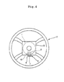
- the cable reel 1 includes a stator 2, which is formed with an annular bottom wall 2a and an annular outer peripheral wall 2b, and a rotor 3 which is formed with the annular upper wall 3a and an annular inner peripheral wall or center axis portion 3b, resulting in the ability to rotate coaxially and relatively.
- a flat cable 5 is housed in a wound condition in an annular hollow space 4 formed by the stator 2 and rotor 3. Opposite ends of the flat cable 5 are fastened to the stator 2 and the rotor 3, respectively, so that the flat cable 5 is wound in or wound out of the hollow space 4 in accordance with the reciprocal rotation of the rotor 3 corresponding to rotation of the steering wheel.
- This construction is the same as the known construction.
- the predetermined rotation phase is maintained upon mounting to the steering wheel by temporarily placing a lateral, generally T-shaped rotation clamping member 6 from an upper position over the stator 2 and the rotor 3 to make it impossible to rotate the rotor 3 relative to the stator 2.
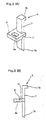
- the rotation clamping members 6 are, as shown in Figs.3(A) and (B), generally T-shaped components formed from a suitable material, such as a synthetic resin, assembled from two parts with a vertical piece 7 extending vertically along the side of the cable reel, and a lateral piece 8 horizontally projecting from about the middle of the vertical piece toward the center of the cable reel.
- a suitable material such as a synthetic resin
- the bottom portion 7a is straight to the very end, but the end of the top portion 7b is bent approximately 90° outward to facilitate holding thereof.
- the lateral piece 8 is provided with an engaging clamp hole 8a which extends generally vertically therethrough (in the thickness direction).
- the stator 2 is provided on the outer surface thereof with an engaging area 9 (notes Figs.1 and 2) including a clamp recess 9a, and the rotor 3 is provided on the upper surface with the projection 10.
- the rotation clamping members 6 are clamped on the peripheral surface of the stator 2 with the bottom portion 7a of the vertical piece 7 inserted into the clamp recess 9a, and are also clamped on the upper surface of the rotor 3 with the projection 10 engaged within the clamp hole 8a of the lateral piece 8, so that the stator 2 and the rotor 3 cannot rotate.
- stator 2 and the rotor 3 are made non-rotatable by operations such that the stator 2 and the rotor 3 are first positioned in the predetermined rotation phase and then, while the end of the bottom portion 7a of the vertical piece 7 of the rotation clamping members 6 enters the clamp recess 9a from above the stator 2 and the rotor 3, the clamp hole 8a of the lateral piece 8 engages with the projection 10 so that the rotation clamping members 6 are positioned on a shoulder of the cable reel 1.
- bottom portion 7a may be formed larger than the clamp recess 9a and is pressed into the clamp recess 9a, or a projection is provided at the end of the bottom portion 7a to engage with a hook provided inside the clamp recess 9a.
- the above-described rotation clamping members 6 are, as shown in Fig.3, connected with the vertical piece 7 through a hinge 11 which is provided for the lateral piece to pivot downwardly easily from the level of the root. That is, a recessed portion is formed along a width direction adjacent the end of the lateral piece 8 connected to the vertical piece 7 to form a thin root.
- the hinge and the lateral piece are formed unitarily and in one piece, and the lateral piece 8 can easily pivot downwardly about the root at the hinge.
- it is possible to form the hinge by cutting the edges of both sides of the lateral piece 8 to form the root as a slender neck.
- the lateral piece and the vertical piece are formed separately and integrated, and upon the integration, the hinge formed by the aforementioned thin portion or the slender neck is provided.
- the cable reel 1 is mounted on the steering apparatus in a temporary rotation clamping condition produced between the rotor 3 and the stator 2 by the aforementioned rotation clamping members 6, and the steering wheel 12 is then mounted over the cable reel 1. After assembling the steering wheel 12, the rotation clamping members, which make impossible for the stator and the rotor to rotate, are removed to release the temporary rotation clamp.
- a hole formerly provided for withdrawing the clamp members is not provided in the wheel hub 13 at the center of the steering wheel 12.
- the top portion 7b of the rotation clamping members 6 is positioned a little higher than the wheel boss 13 near the periphery of the wheel hub 13.
- the operator In order to remove the rotation clamping members 6, it is sufficient for the operator to hold and lift up the top portion 7b of the rotation clamping members 6. As shown in Fig.5(b), the lateral piece 8 of the rotation clamping members 6, which are lifted up, engages the periphery ofthe wheel hub 13, and pivots downwardly about the root of the hinge, and can be smoothly withdrawn through the outer surface of the wheel hub 13, so that the rotation clamping members are quickly removed.
- the rotation clamping members are temporarily placed over the stator and the rotor. Since the lateral piece is connected with the vertical piece through a hinge which allows the lateral piece to pivot downwardly from the root of the hinge, when the parts are lifted up to release the rotation clamp of the rotor, the lateral piece engages against the periphery of the wheel hub, pivots downwardly from the level of the root, and is withdrawn smoothly through the outer surface of the wheel hub. Therefore, the rotation clamping members are quickly removed and smartly evade the wheel hub even if a removal hole is not provided. Additionally, since it is not necessary to provide for the wheel hub with a hole, there is no concern regarding a reduction in strength of the wheel by provision of the hole for removal of the clamping members.
- the hinge which permits the lateral piece of the rotation clamping members lower is formed unitarily and in one piece with the lateral piece with the root of the lateral piece formed to have a thin or slender neck portion, the hinge is able to be simultaneously formed upon forming the rotation clamping members.
- a mechanism for removing rotation clamping members in which a rotor of a cable reel is temporarily clamped to a stator.
- Rotation clamping members which are temporarily positioned over the stator and the rotor of the cable reel are connected with a vertical piece through a hinge that allows a lateral piece to pivot downwardly easily from a root.
- the lateral piece of the rotation clamping members which is lifted up engages against the periphery of the wheel hub followed by downward pivoting from the root, so that the clamping members are removed smoothly through the side of the wheel boss.
Landscapes
- Engineering & Computer Science (AREA)
- Mechanical Engineering (AREA)
- Steering Controls (AREA)
- Manufacture Of Motors, Generators (AREA)
Abstract
Description
Claims (10)
- A temporary rotation clamping mechanism for a cable reel, the cable reel being mountable on a steering apparatus and including a rotor and a stator, and wherein the rotor is temporarily clamped to the stator through rotation clamping members, said rotation clamping members comprising:a vertical piece positionable in an axial direction of the cable reel and a lateral piece horizontally projecting toward the center of the cable reel from a middle position of said vertical piece, and said lateral piece being connected with said vertical piece through a hinge which is pivotable downwardly;a bottom portion of said vertical piece is insertable into an engaging area provided on an outer peripheral surface of the stator so that said lateral piece projects over an upper surface of the rotor, and a projection on the upper surface of the rotor is insertable into an engaging clamp hole provided in said lateral piece to temporarily stop rotation of the rotor; andwhen releasing the rotation clamping, said lateral piece and the rotor are disengaged by holding and pulling up an upper portion of said vertical piece to allow said lateral piece to be lifted up through the outside of a wheel hub by engagement of said lateral piece against a periphery of the wheel hub followed by downward bending of said hinge, so that the rotation clamping members may be removed.
- The temporary rotation clamping mechanism in a cable reel as claimed in claim 1, in which said hinge is formed unitarily and in one piece with said lateral piece to include a thin neck portion provided at the root of said lateral piece, and said vertical piece is formed unitarily and in one piece with said hinge.
- The temporary rotation clamping mechanism in a cable reel as claimed in claim 1, wherein said hinge is formed unitarily and in one piece with said lateral piece, and said lateral piece is separately formed and fixedly attached to said vertical piece.
- A temporary rotation clamping mechanism for a cable reel, the cable reel being mountable on a steering apparatus and including a rotor and a stator, said rotation clamping mechanism comprising:wherein said lateral piece is configured to project over an upper surface of the rotor during clamping with said projection received in said engaging clamp hole to provide rotation clamping, whereby in order to release the rotation clamping, said lateral piece and the rotor are disengageable by pulling a portion of said vertical piece to allow said lateral piece to be lifted up through the outside of a wheel hub by engagement of said lateral piece against a periphery of the wheel hub followed by pivoting of said hinge, so that said rotation clamping members may be removed.a vertical piece positionable in an axial direction of the cable reel;a lateral piece projecting toward the center of the cable reel, said lateral piece hingedly connected to said vertical piece and including an engaging clamp hole;an engaging area provided on an outer peripheral surface of the stator to receive a lower portion of said vertical piece which is insertable therein; anda projection on the upper surface of the rotor being insertable into said engaging clamp hole provided in said lateral piece to temporarily stop rotation of the rotor;
- The temporary rotation clamping mechanism as recited in claim 1, wherein said lateral piece is positioned at a central position of said vertical piece.
- The temporary rotation clamping mechanism as recited in claim 5, wherein said lateral piece is hingedly connected with said vertical piece through a hinge which is pivotable downwardly.
- The temporary rotation clamping mechanism as recited in claim 6, wherein said hinge is formed unitarily and in one piece with said lateral piece.
- The temporary rotation clamping mechanism as recited in claim 7, wherein said hinge includes a thin neck portion provided at the root of said lateral piece.
- The temporary rotation clamping mechanism as recited in claim 8, wherein said vertical piece is formed unitarily and in one piece with said hinge.
- The temporary rotation clamping mechanism as recited in claim 6, wherein said hinge is formed unitarily and in one piece with said lateral piece, and said lateral piece is separately formed and fixedly attached to said vertical piece.
Applications Claiming Priority (2)
| Application Number | Priority Date | Filing Date | Title |
|---|---|---|---|
| JP2000213082A JP2002029335A (en) | 2000-07-13 | 2000-07-13 | Temporary rotation fixing structure for cable reel |
| JP2000213082 | 2000-07-13 |
Publications (2)
| Publication Number | Publication Date |
|---|---|
| EP1172904A2 true EP1172904A2 (en) | 2002-01-16 |
| EP1172904A3 EP1172904A3 (en) | 2004-02-11 |
Family
ID=18708898
Family Applications (1)
| Application Number | Title | Priority Date | Filing Date |
|---|---|---|---|
| EP01115208A Withdrawn EP1172904A3 (en) | 2000-07-13 | 2001-06-22 | A temporary rotation clamping mechanism for a cable reel |
Country Status (3)
| Country | Link |
|---|---|
| US (1) | US6488225B2 (en) |
| EP (1) | EP1172904A3 (en) |
| JP (1) | JP2002029335A (en) |
Families Citing this family (3)
| Publication number | Priority date | Publication date | Assignee | Title |
|---|---|---|---|---|
| CA2749073C (en) | 2010-08-13 | 2015-05-19 | Tanner K. Stewart | Spool lock |
| US9627832B2 (en) * | 2014-08-04 | 2017-04-18 | American Furukawa, Inc. | Lock member for a rotary connector device |
| US10286861B2 (en) * | 2015-07-02 | 2019-05-14 | Honda Motor Co., Ltd. | Cable reel |
Family Cites Families (11)
| Publication number | Priority date | Publication date | Assignee | Title |
|---|---|---|---|---|
| JP2550413Y2 (en) * | 1991-11-26 | 1997-10-15 | 古河電気工業株式会社 | Rotating connector |
| FR2710597B1 (en) * | 1993-10-01 | 1995-11-24 | Valeo Electronique | Rotating switch for motor vehicle. |
| US5593310A (en) * | 1993-12-27 | 1997-01-14 | Nihon Plast Co., Ltd. | Cable type electric connector |
| KR0140588B1 (en) * | 1994-03-09 | 1998-07-01 | 가다오까 마사다까 | Rotating Connector |
| JPH0837072A (en) | 1994-07-22 | 1996-02-06 | Tokai Rika Co Ltd | Roll connector temporary fixing mechanism |
| JP3025626B2 (en) * | 1995-05-11 | 2000-03-27 | 矢崎総業株式会社 | Lock mechanism for electrical connection device |
| JP3273540B2 (en) * | 1996-02-07 | 2002-04-08 | アルプス電気株式会社 | Rotating connector mounting structure |
| JP3273426B2 (en) * | 1996-04-26 | 2002-04-08 | アルプス電気株式会社 | Rotating connector |
| US6059590A (en) * | 1999-04-08 | 2000-05-09 | Methode Electronics, Inc. | Clockspring tamper proof external lock |
| JP3700484B2 (en) * | 1999-08-18 | 2005-09-28 | 松下電器産業株式会社 | Rotating connector |
| JP3681623B2 (en) * | 2000-08-25 | 2005-08-10 | アルプス電気株式会社 | Rotating connector |
-
2000
- 2000-07-13 JP JP2000213082A patent/JP2002029335A/en not_active Withdrawn
-
2001
- 2001-06-22 EP EP01115208A patent/EP1172904A3/en not_active Withdrawn
- 2001-06-29 US US09/893,672 patent/US6488225B2/en not_active Expired - Fee Related
Also Published As
| Publication number | Publication date |
|---|---|
| JP2002029335A (en) | 2002-01-29 |
| US20020005450A1 (en) | 2002-01-17 |
| US6488225B2 (en) | 2002-12-03 |
| EP1172904A3 (en) | 2004-02-11 |
Similar Documents
| Publication | Publication Date | Title |
|---|---|---|
| US6488225B2 (en) | Temporary rotation clamping mechanism for a cable reel | |
| JPH09293576A (en) | Rotating connector | |
| EP1020876A3 (en) | Device for removing a wire harness from a vehicle | |
| US12565396B1 (en) | Wire rollers | |
| CN221534032U (en) | A multifunctional treatment vehicle | |
| US20220144029A1 (en) | Retention mount for trailer cord | |
| JP2000161538A (en) | Protector | |
| JP3262944B2 (en) | Cable reel | |
| JPH09253086A (en) | Surgical abdominal wall tractor | |
| JPH10255572A (en) | Grommet | |
| JP3075708U (en) | Hanging device for folding bicycle and folding bicycle provided with this hanging device | |
| KR100534302B1 (en) | Automobile Spare Tire Moving Apparatus | |
| JP2566017Y2 (en) | Holders for electric wires | |
| JPS633827B2 (en) | ||
| JPH0948312A (en) | Steering wheel with airbag device | |
| KR200498003Y1 (en) | An electric assist device to provide an auxiliary power source for a wheelchair | |
| JPH11144828A (en) | Cable reel stopper structure | |
| JP2571440Y2 (en) | Wire harness protector | |
| JP2594457Y2 (en) | Temporary fixing structure in the current supply device for vehicle airbag | |
| JP2500544Y2 (en) | Spare tire storage device | |
| JP2005312629A (en) | Wheelchair fixing device | |
| JP3109169U (en) | Auxiliary equipment for children's bicycles | |
| JPH0290154U (en) | ||
| JPS6312060Y2 (en) | ||
| JP2000337047A (en) | Fabric fixing structure of roll screen and fabric fixing method |
Legal Events
| Date | Code | Title | Description |
|---|---|---|---|
| PUAI | Public reference made under article 153(3) epc to a published international application that has entered the european phase |
Free format text: ORIGINAL CODE: 0009012 |
|
| 17P | Request for examination filed |
Effective date: 20010622 |
|
| AK | Designated contracting states |
Kind code of ref document: A2 Designated state(s): AT BE CH CY DE DK ES FI FR GB GR IE IT LI LU MC NL PT SE TR |
|
| AX | Request for extension of the european patent |
Free format text: AL;LT;LV;MK;RO;SI |
|
| PUAL | Search report despatched |
Free format text: ORIGINAL CODE: 0009013 |
|
| AK | Designated contracting states |
Kind code of ref document: A3 Designated state(s): AT BE CH CY DE DK ES FI FR GB GR IE IT LI LU MC NL PT SE TR |
|
| AX | Request for extension of the european patent |
Extension state: AL LT LV MK RO SI |
|
| AKX | Designation fees paid |
Designated state(s): DE FR GB IT |
|
| STAA | Information on the status of an ep patent application or granted ep patent |
Free format text: STATUS: THE APPLICATION IS DEEMED TO BE WITHDRAWN |
|
| 18D | Application deemed to be withdrawn |
Effective date: 20040810 |
|
| R18D | Application deemed to be withdrawn (corrected) |
Effective date: 20040812 |