EP1172896A2 - Waterproof connector - Google Patents
Waterproof connector Download PDFInfo
- Publication number
- EP1172896A2 EP1172896A2 EP01116570A EP01116570A EP1172896A2 EP 1172896 A2 EP1172896 A2 EP 1172896A2 EP 01116570 A EP01116570 A EP 01116570A EP 01116570 A EP01116570 A EP 01116570A EP 1172896 A2 EP1172896 A2 EP 1172896A2
- Authority
- EP
- European Patent Office
- Prior art keywords
- waterproof connector
- cover
- covers
- sealing member
- holes
- Prior art date
- Legal status (The legal status is an assumption and is not a legal conclusion. Google has not performed a legal analysis and makes no representation as to the accuracy of the status listed.)
- Granted
Links
Images



Classifications
-
- H—ELECTRICITY
- H01—ELECTRIC ELEMENTS
- H01R—ELECTRICALLY-CONDUCTIVE CONNECTIONS; STRUCTURAL ASSOCIATIONS OF A PLURALITY OF MUTUALLY-INSULATED ELECTRICAL CONNECTING ELEMENTS; COUPLING DEVICES; CURRENT COLLECTORS
- H01R13/00—Details of coupling devices of the kinds covered by groups H01R12/70 or H01R24/00 - H01R33/00
- H01R13/46—Bases; Cases
- H01R13/52—Dustproof, splashproof, drip-proof, waterproof, or flameproof cases
-
- H—ELECTRICITY
- H01—ELECTRIC ELEMENTS
- H01R—ELECTRICALLY-CONDUCTIVE CONNECTIONS; STRUCTURAL ASSOCIATIONS OF A PLURALITY OF MUTUALLY-INSULATED ELECTRICAL CONNECTING ELEMENTS; COUPLING DEVICES; CURRENT COLLECTORS
- H01R13/00—Details of coupling devices of the kinds covered by groups H01R12/70 or H01R24/00 - H01R33/00
- H01R13/46—Bases; Cases
- H01R13/52—Dustproof, splashproof, drip-proof, waterproof, or flameproof cases
- H01R13/5205—Sealing means between cable and housing, e.g. grommet
- H01R13/5208—Sealing means between cable and housing, e.g. grommet having at least two cable receiving openings
Definitions
- the present invention belongs to a technical field of waterproof connectors, and particularly relates to a waterproof connector wherein a plurality of terminals can be inserted into a housing and collectively waterproofed.
- a collectively-waterproofed type connector wherein an opening in a housing on its terminal insertion side is sealed with a sealing member and a wired terminal is inserted in each of a plurality of through holes in this sealing member and all the terminals are collectively waterproofed.
- This collectively-waterproofed type connector has a merit that the connector of this type can be compactified more easily than an individually-waterproofed-cell type connector wherein a housing is provided with a number of cells corresponding to the number of terminals and every individual cell and its terminal are sealed by inserting a sealing member into the cell.
- each through hole that is not to be used is fitted with a plug to close the hole.
- a waterproof connector is provided with separate plugs, it may result in an increase in cost.
- such a work of manually inserting each plug into a through hole is quite troublesome and deteriorates the workability.
- JP-A-(Hei)-36 824 wherein a retainer for holding a sealing member in a housing is provided with plugs that can be cut off and a through hole into which a terminal is to be inserted is made open by cutting its plug off the retainer.
- the technique of this proposal is for waterproof connectors having a retainer for holding a sealing member, it can not be applied to a waterproof connector wherein a sealing member is inserted into an opening in a housing on its terminal insertion side as described above.
- parts functioning as plug of the waterproof connector of the proposal are to be formed integrally with the retainer.
- the retainer which is required to have a rigidity sufficient to hold the sealing member, is usually made of a resin, etc., and the work of opening a through hole by cutting a part functioning as plug away from the retainer at a connecting part of the resin, etc. will require a considerable force, and its workability is bad.
- the need of the two-stage operation of opening a through hole by cutting off a part functioning as plug and inserting a terminal poses a problem of troublesomeness.
- the present invention is designed for a collectively-waterproofed type connector wherein a sealing member is inserted into an opening in a housing on its terminal insertion side.
- One object of the invention is to ease the work of opening a through hole, by integrally connecting covers for closing through holes onto the sealing member and, when necessary, breaking a cover to open a through hole.
- Another object of the present invention is to make it possible to insert a wired terminal into the waterproof connector with a single touch by making each cover breakable by the pressing force of a terminal to open a through hole.
- the waterproof connector of the present invention comprises a housing in which a terminal is to be held, having an opening on its terminal insertion side, a sealing member inserted in the opening of the housing, having a sealing part, which is provided on the outer circumference of the sealing member and airtightly contacts the inner surface of the opening, and having a plurality of through holes, each of said through holes allowing a terminal to pass through and the inner surface of each of said through holes being able to airtightly contact an electric wire, and covers provided for the respective through holes, a circumferential part of each of the covers being integrally connected over the entire circumference to the circumferential wall of the through hole, and the circumferential part being formed into a thickness that can be broken by human force.
- this waterproof connector When this waterproof connector is to be used, a cover that closes a through hole into which a terminal is to be inserted is pulled outwards away from the sealing member or a wired terminal is forced into a cover that closes a through hole into which a terminal is to be inserted to pull inwards the cover from the sealing member.
- the cover will be broken at its circumferential part under the effect of the tensile force, shearing force, etc., and the cover will come off the sealing member to open the through hole. Then the wired terminal is inserted into this opened through hole.
- the waterproof connector As a through hole that is not to be inserted with a terminal is closed without any gap by a cover that is integrally connected, the waterproof connector is waterproofed from the outside.
- the cover is integrally connected to the sealing member, there is no need of separately providing any plug. This reduces the cost, and as the work of manually inserting plug into the through hole is eliminated, the workability is improved.
- the cover is integrally connected with the sealing member, the cover is formed out of rubber, etc. of which tensile strength and shearing strength are lower than those of resins and the like. Thus the work of pulling and breaking the covers can be done more easily, and the required force for the work is smaller than that required for cutting the part functioning as plug away from the retainer, and the workability is improved.
- the wired terminal can be inserted into the waterproof connector with a single touch.
- This waterproof connector is one of the correctively-waterproofed type wherein a sealing member is inserted into an opening in the housing on its terminal insertion side, and as the need of separately providing plug is eliminated, the cost can be reduced, and as the work of manually inserting a plug into a through hole is eliminated, the workability can be enhanced. Moreover, the workability of opening a through hole can be improved significantly greater than the work of cutting off a part functioning as plug from the retainer. Furthermore, when a cover is to be removed by pushing a wired terminal into the cover, the wired terminal can be inserted into the waterproof connector with a single touch, and the workability of installing the wired terminal is enhanced.
- Fig. 1 is a perspective view of a waterproof connector according to the first embodiment of the present invention.
- Fig. 2 is a longitudinal sectional view of the above-mentioned waterproof connector.
- Fig. 3A, Fig. 3B and Fig. 3C show a sealing member with covers in the above-mentioned waterproof connector.
- Fig. 3A is a side view
- Fig. 3B is a front view
- Fig. 3C is a rear view, respectively.
- Fig. 4A and Fig. 4B are explanatory drawings showing steps of inserting a wired terminal into the above-mentioned waterproof connector.
- Fig. 4A shows a state before insertion
- Fig. 4B shows a state after insertion, respectively.
- Fig. 5 is a longitudinal sectional view showing a sealing member with covers in a waterproof connector according to the second embodiment of the present invention.
- Fig. 6 is a longitudinal sectional view showing a sealing member with covers in a waterproof connector according to the third embodiment of the present invention.
- Fig. 7A, Fig. 7B and Fig. 7C show a sealing member with covers in a waterproof connector according to the fourth embodiment of the present invention.
- Fig. 7A is a side view
- Fig. 7B is a front view
- Fig. 7C is a rear view, respectively.
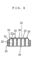
- Fig. 8 is a sectional view along a line VIII-VIII in Fig. 7B.
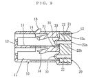
- Fig. 9 is a longitudinal sectional view of a waterproof connector of the fifth embodiment of the present invention.
- Fig. 10A, Fig. 10B and Fig. 10C show a sealing member with covers in the waterproof connector of the fifth embodiment.
- Fig. 10A is a side view
- Fig. 10B is a front view
- Fig. 10C is a rear view, respectively.
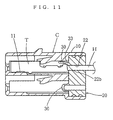
- Fig. 11 is an explanatory drawing showing steps of inserting a wired terminal into the waterproof connector of the fifth embodiment.
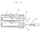
- Fig. 12 is an explanatory drawing showing steps of inserting a wired terminal into a waterproof connector differs from the present invention.
- Fig. 1 and Fig. 2 show a waterproof connector C according to the first embodiment.
- terminals of both connectors will be airtightly connected with each other in the housings of both waterproof connectors.
- up to five terminals can be inserted.
- the number of poles of the waterproof connector of the present invention is not limited in any way by this embodiment.
- 10 denotes a housing of the waterproof connector C, and this housing 10 is formed of an insulating material into a roughly box-shaped form. Inside the housing 10, a plurality of cells 11 are formed to hold terminals T. An opening 12 of the terminal insertion side is formed in one end of the housing 10, and the respective cells 11 are connected to this opening 12. Openings 13 of the connection side are formed in the other end of the housing 10 and each cell 11 is connected to an opening 13. In this embodiment, each cell 11 is provided with a dedicated opening 13, but a plurality of cells may be connected to a single opening of the connection side. Each terminal T is made to connect to a terminal of the counterpart waterproof connector through an opening 13.
- the terminals T of this embodiment are female terminals of a roughly boxed form, but the present invention also covers waterproof connector into which male terminals are inserted.
- the terminals T of this embodiment are crimp terminals, but terminals T are not limited in any way to crimp terminal.
- the opening 12 in the housing 10 is formed to have a certain depth in the insertion direction of terminals T.
- a sealing member 20 having sealability is inserted into this opening 12.
- the sealing member 20 is formed of an elastic material that exhibits airtightness such as rubber, and is formed in such a way that it fits into the above-mentioned opening 12 in a little compressed state due to its elasticity.
- the sealing member 20 has, on its outer circumference, a sealing part 21 that airtightly contacts the inner surface 12a of the above-mentioned opening 12.
- seal lips are formed on the sealing part 21, but the sealing part 21 may be formed flat.
- the sealing member 20 has a plurality of through holes 22, each of the through holes 22 allowing a terminal T to pass through and the inner surface of each of the through holes 22 being able to airtightly contact an electric wire H.
- Each of these through holes 22 can be expanded to an extent that when a terminal T is inserted, the terminal T can pass through it thanks to the elasticity of the sealing member 20.
- an electric wire H is put through the through hole 22, its internal surface will elastically contact the electric wire H due to the elasticity of the sealing member 20 to exhibit sealability.
- This sealing member 20 is provided with a cover 30 for each through hole 22.
- the circumferential part 31 of this cover 30 is integrally connected over the entire circumference to the circumferential wall of the through hole 22.
- the cover 30 may be arranged in any position along the through hole 22; it may be arranged on the outer end, the inner end or in the middle of the through hole 22. In this embodiment, the cover 30 is arranged on the outer end 22a of the through hole 22.
- the circumferential part 31 of the cover 30 is integrally connected over the entire circumference to the circumferential wall of the through hole 22 at the outer end 22a thereof.
- the form of the cover 30 is not specifically limited. However, in this embodiment, the cover 30 is made to extrude outwards beyond the outer surface of the sealing member 30, and the cover 30 is formed into an approximately bowl shape.
- the circumferential part 31 of the cover 30 is formed to have a thickness that can be broken by human physical power.
- the circumferential part 31 is formed to have a thickness that can be broken when a human force is exerted to the cover 30.
- the human force that is exerted to the cover 30 includes tensile forces that work in the insertion direction of the terminals T or in the direction opposite to it, shearing forces that act in a direction perpendicular to the insertion direction of the terminals T, and forces that are combinations of the former and the latter.
- the thickness that can be broken by human force is a thickness that can be broken by tensile force, shearing force, etc. when the cover 30 is pulled by human power outwards from the sealing member 20.
- the material of the cover 30 is considered.
- 14 denotes a lance for engaging a terminal T and is provided when necessary.
- the present invention includes embodiments wherein terminals T are provided with a lance.
- 15 denotes a locking part for engaging the waterproof connector to a counterpart waterproof connector. It is provided when necessary.
- the thickness of the circumferential part 31 of the cover 30 is formed to be thinner than those of other portions of the cover 30.
- a cover 30 closing a through hole 22 into which a terminal T is to be inserted is pulled outwards from the sealing member 20. Under tensile force and shearing force, the cover 30 will be broken in the circumferential part 31 and the cover 30 will come off the sealing member 20 to open the through hole 22. As shown in Fig. 4B, a wired terminal T is inserted into this opened through hole 22. As through holes 22 into which no terminal T is to be inserted are closed without any gap by covers 30 that are integrally connected over entire circumference to the circumferential walls of through holes 22, they are completely waterproofed against the outside of the waterproof connector C.
- the number of broken cover(s) and unbroken cover(s) of the waterproof connector of the present invention are not limited by this embodiment.
- Fig. 12 shows a waterproof connector differs from the present invention and compared with the present invention.
- This waterproof connector comprises a housing 51 having a construction similar to that of the first embodiment, and a sealing member 52 which is inserted into an opening in the housing 51 on its terminal insertion side, which has on its outer circumference a sealing part that airtightly contacts the inner surface of the above-mentioned opening, and which has a plurality of through holes 53 through which terminals can be passed and of which internal surfaces airtightly contact electric wires.
- a plug 54 is inserted into every through hole 53 that is not to be used.
- the waterproof connector C of the first embodiment has no need of separately providing plugs 54 as covers 30 are integrally connected to the sealing member 20. Hence the cost is reduced.
- the workability is improved.
- the covers 30 are integrally connected with the sealing member 20
- the covers 30 are formed of rubber or the like of which tensile strength and shearing strength are lower than those of resins or the like, and the work of breaking the covers 30 is easier. Accordingly, the force required to break a cover 30 in the waterproof connector C according to the first embodiment is significantly smaller than that required in the work of cutting a part functioning as plug away from a retainer in the technique proposed in JP-A-(Hei)6-36824; thus the workability is improved.
- the present invention does not limit in any way the thickness of the circumferential part of the cover.
- the thickness of the circumferential part 31 of the cover 30 is made thinner than other portions of the cover 30 as is the case in the waterproof connector C of the first embodiment, stresses tend to concentrate in the circumferential part 31 of the cover 30, and the cover 30 will reliably break at the circumferential part 31.
- the cover 30 can be removed neatly to open a neat through hole 22.
- each cover 30 of the second embodiment is formed solid except its circumferential part 31. Moreover, the amount of protrusion of the cover 30 outwards from the external surface of the sealing member 20 is set longer than the cover 30 of the first embodiment.
- the waterproof connector C of the third embodiment will be described.
- the waterproof connector C of the third embodiment differs from the waterproof connector C of the first embodiment only in the form of the covers 30. Accordingly, the same mark is given to the same member with the first embodiment, and the description of the first embodiment is quoted intact and only points of difference regarding the form of the covers 30 will be described.
- the covers 30 of the third embodiment are formed to a substantially even thickness.
- the waterproof connector C of the fourth embodiment will be described.
- the waterproof connector C of the fourth embodiment has a larger number of poles than the waterproof connector C of the first embodiment.
- the waterproof connector C of the fourth embodiment substantially differs from the waterproof connector C of the first embodiment only in the form of the covers 30. Accordingly, the same mark is given to the same member with the first embodiment, and the description of the first embodiment is quoted intact and only points of difference regarding the form of the covers 30 will be described.
- some covers 30 out of the total covers 30 are provided with connecting members 32 that are integrally connected to a plurality of covers 30.
- Through holes 22 corresponding to the covers 30 that are connected by the connecting members 32 are through holes 22 that are jointly used when used and through holes 22 non of which is used when not used.
- the connecting members 32 are formed into bars, but their forms are discretionary.
- the actions and effects of the first embodiment can be obtained. Moreover, if a connecting member 32 is held and pulled, a plurality of covers 30 that are connected to the connecting member 32 will be removed from the sealing member 20 by one effort, and through holes 22 corresponding to these covers 30 will be opened by one effort. Thus the workability is good.
- the fourth embodiment is suitable when a combination of through holes 22 to be opened is definite.
- each cover 30 is located at the inner end 22b of a through hole 22.
- the circumferential part 31 of the cover 30 is integrally connected over the entire circumference to the circumferential wall of the inner end 22b of the through hole 22.
- the configuration of the cover 30 is not limited specifically, but in this embodiment, the cover 30 is projected inwards from the inner surface of the sealing member 20, namely, into the cell 11, and the cover 30 is formed into an approximately bowl shape.
- the circumferential part 31 of the cover 30 is formed to a thickness that can be broken by human power.
- the circumferential part 31 is formed to have a thickness that can be broken when a human force is exerted to the cover 30.
- the human force that is exerted to the cover 30 includes tensile forces that work in the insertion direction of a terminal T.
- the thickness that can be broken by human power is a thickness that can be broken by tensile force, shearing force, etc. when a man pushes a wired terminal T into a cover 30 to pull the cover 30 inwards away from the sealing member 20. When this thickness is determined, the material of the cover 30 is considered.
- the thickness of the circumferential part 31 of the cover 30 is made thinner than the thicknesses of other parts of the cover 30.
- a reinforcing part 33 is provided at a part of the circumferential part 31 of the cover 30.
- This reinforcing part 33 is thicker than other parts and connects the cover 30 other than its circumferential part and the circumferential wall of the through hole 33.
- the thickness of this reinforcing part 33 is set to a thickness that can not be broken by human force.
- a wired terminal T is pushed into a cover 30 closing a through hole 22 into which the terminal T is to be inserted, to pull the cover 30 inwards away from the sealing member 20.
- the cover 30 Under tensile force, shearing force, etc., the cover 30 will break at its circumferential part 31, and the cover 30 will come off the sealing member 20 to open the through hole 22.
- the wired terminal T will be directly inserted into this opened through hole 22.
- the waterproof connector C is completely waterproofed from the outside.
- the wired terminal T can be inserted into the waterproof connector C with a single touch; thus the workability of inserting a wired terminal T is excellent.
- the waterproof connector C of the fifth embodiment has covers 30 that are integrally connected to the sealing member 20. Hence there is no need of separately providing plugs 54, and this results in reduction in cost. Moreover, the work of manually inserting plugs 54 into through holes 22 and breaking the ends of the plugs 54 is eliminated, and this results in improvement in workability.
- the covers 30 are integrally connected to the sealing member 20, and the covers 30 are formed of rubber or the like of which tensile strength and shearing strength are lower than those of resins or the like. Hence breaking the covers 30 can be done more easily. Accordingly, the force required to break away the covers 30 in the waterproof connector C of the fifth embodiment is significantly smaller than the force required by cutting parts functioning as plug away from the retainer in the technique proposed in JP-A- (Hei) 6-36824, resulting in a better workability.
- the present invention does not limit the thickness of the circumferential part of the covers, but when the thickness of the circumferential part 31 of the covers 30 is formed thinner than the thicknesses of other portions of the covers 30, like the case of the waterproof connector C of the fifth embodiment, stresses tend to concentrate in the circumferential part 31 of the covers 30 and the covers 30 will reliably break at their circumferential parts 31. As a result, the covers 30 will be removed neatly to open neat through holes 22.
- the reinforcing part 33 will not break even when the other portions of the circumferential part 31 are broken, and the cover 30 will be kept connected to the sealing member 20 by means of the reinforcing part 33. As a result, the cover 30 will never be lost in or out of the waterproof connector C. Thus covers 30 are prevented from causing troubles such as defective contact by dropping into the contacting parts of terminals.
- the present invention includes all embodiments that combine features of the above-mentioned embodiments.
- the present invention includes, for example, embodiments wherein connecting members are provided to the first embodiment through the third embodiment and the fifth embodiment, embodiments wherein reinforcing parts are provided to the first embodiment through the fourth embodiment, an embodiment wherein no reinforcing parts are provided in the fifth embodiment, and embodiments wherein covers are provided at the inner ends of through holes like the case of the fifth embodiment and the form of the covers is the cover form of the second embodiment or the third embodiment.
- the present invention includes an embodiment wherein the covers are provided in the middle of through holes and the circumferential part of each cover is integrally connected over the entire circumference to the internal wall of the through hole and the circumferential part of each cover is formed to have a thickness that is breakable by human force, an embodiment wherein covers are made to protrude outwards from the external surface of the sealing member in this embodiment, an embodiment wherein connecting members are provided in this embodiment, and an embodiment wherein reinforcing parts are provided in this embodiment.
- the second waterproof connector is a waterproof connector according to the first waterproof connector, wherein the covers protrude outwards away from the external surface of the sealing member.
- the third waterproof connector is a waterproof connector according to the first waterproof connector or the second waterproof connector, wherein the thickness of the circumferential part of each cover is formed to be thinner than the thicknesses of other portions of the cover.
- the fourth waterproof connector is a waterproof connector according to any one of the first waterproof connector through the third waterproof connector, further comprising a connecting member or connecting members integrally connected to some covers out of the total covers.
- the fifth waterproof connector is a waterproof connector according to any one of the first waterproof connector through the fourth waterproof connector, further comprising reinforcing parts, each of which is provided at a part of the circumferential part of the cover, is thicker than other parts, and connects the cover other than its circumferential part and the circumferential wall of the through hole.
Landscapes
- Connector Housings Or Holding Contact Members (AREA)
Abstract

Description
Claims (5)
- A waterproof connector (C) comprising :a housing (10) in which a terminal (T) is to be held, having an opening (12) on its terminal insertion side,a sealing member (20) inserted in the opening (12) of the housing (10), having a sealing part (21), which is provided on the outer circumference of the sealing member (20) and airtightly contacts the inner surface (12a) of the opening (12), and having a plurality of through holes (22), each of said through holes (22) allowing a terminal (T) to pass through and the inner surface of each of said through holes (22) being able to airtightly contact an electric wire (H), andcovers (30) provided for the respective through holes (22), a circumferential part (31) of each of the covers (22) being integrally connected over the entire circumference to the circumferential wall of the through hole (22), and the circumferential part (31) being formed into a thickness that can be broken by human force.
- A waterproof connector (C) as recited in claim 1, wherein the covers protrude outwards away from the external surface of the sealing member.
- A waterproof connector (C) as recited in claim 1 or 2, wherein the thickness of the circumferential part (31) of each cover (30) is formed to be thinner than the thicknesses of other portions of the cover (30).
- A waterproof connector (C) as recited in claim 1, 2 or 3, further comprising :
a connecting member or connecting members (32) integrally connected to some covers out of the total covers (30). - A waterproof connector (C) as recited in claim 1, 2, 3 or 4, further comprising :
reinforcing parts (33), each of which is provided at a part of the circumferential part (31) of the cover (30), is thicker than other parts, and connects the cover (30) other than its circumferential part (31) and the circumferential wall of the through hole (22).
Applications Claiming Priority (2)
| Application Number | Priority Date | Filing Date | Title |
|---|---|---|---|
| JP2000213529 | 2000-07-13 | ||
| JP2000213529A JP3380528B2 (en) | 2000-07-13 | 2000-07-13 | Waterproof connector |
Publications (3)
| Publication Number | Publication Date |
|---|---|
| EP1172896A2 true EP1172896A2 (en) | 2002-01-16 |
| EP1172896A3 EP1172896A3 (en) | 2003-05-07 |
| EP1172896B1 EP1172896B1 (en) | 2005-03-23 |
Family
ID=18709269
Family Applications (1)
| Application Number | Title | Priority Date | Filing Date |
|---|---|---|---|
| EP01116570A Expired - Lifetime EP1172896B1 (en) | 2000-07-13 | 2001-07-09 | Waterproof connector |
Country Status (8)
| Country | Link |
|---|---|
| US (1) | US6595800B2 (en) |
| EP (1) | EP1172896B1 (en) |
| JP (1) | JP3380528B2 (en) |
| KR (1) | KR100797496B1 (en) |
| CN (1) | CN1193465C (en) |
| DE (1) | DE60109529T2 (en) |
| HK (1) | HK1042989B (en) |
| TW (1) | TW493296B (en) |
Cited By (2)
| Publication number | Priority date | Publication date | Assignee | Title |
|---|---|---|---|---|
| WO2006108442A1 (en) * | 2005-04-11 | 2006-10-19 | Fci | Improved grommet-type joint for electrical connector, and electrical connector comprising such a joint |
| US11539159B2 (en) * | 2018-08-17 | 2022-12-27 | Volkswagen Aktiengesellschaft | Plug connector |
Families Citing this family (22)
| Publication number | Priority date | Publication date | Assignee | Title |
|---|---|---|---|---|
| US7377820B2 (en) * | 2004-11-19 | 2008-05-27 | J.S.T. Corporation | Terminal having a protrusion for preventing incorrect insertion |
| JP2008536277A (en) * | 2005-04-11 | 2008-09-04 | エフシーアイ | Grommet for electrical connector and electrical connector equipped with such grommet |
| KR100810697B1 (en) * | 2006-03-03 | 2008-03-07 | (주)네스라이트 | Waterproof wire connector |
| DE102006032642B4 (en) * | 2006-07-13 | 2010-03-18 | Yazaki Europe Ltd., Hemel Hempstead | Connectors |
| US20090181567A1 (en) * | 2008-01-14 | 2009-07-16 | Lincoln Global, Inc. | Sealed connector |
| ES2678062T3 (en) | 2008-07-10 | 2018-08-08 | Chengdu Argangle Technology Co., Ltd. | Waterproof insulation connector |
| US7997931B2 (en) * | 2009-12-11 | 2011-08-16 | Aerovironment, Inc. | Waterproof electrical connector and system |
| JP4981119B2 (en) * | 2009-12-18 | 2012-07-18 | タイコエレクトロニクスジャパン合同会社 | Wire seal, wire seal manufacturing method, and waterproof connector |
| TW201232947A (en) * | 2011-01-19 | 2012-08-01 | Vigatec Co Ltd | Water proof cover and connector using the same |
| DE102011081977A1 (en) | 2011-09-01 | 2013-03-07 | Endress + Hauser Process Solutions Ag | Plug for use with socket for connecting Ethernet cables, has housing receiving electrical plug-in contact and comprising internal and external screw threads for moving electrical plug-in contact along longitudinal axis of housing |
| CN102723044B (en) * | 2012-07-03 | 2014-04-16 | 周巍 | Terminal sealing device |
| KR101470276B1 (en) * | 2014-02-18 | 2014-12-05 | 현대자동차주식회사 | Connector for vehicle |
| JP6488977B2 (en) * | 2015-10-08 | 2019-03-27 | 住友電装株式会社 | Waterproof connector |
| US10044132B2 (en) * | 2016-04-22 | 2018-08-07 | Yazaki North America, Inc. | Cable seal connector with punch-out capability for unused cavities |
| CN111278621A (en) | 2017-10-30 | 2020-06-12 | 株式会社可乐丽 | Waterproof member and electronic device provided with the same, waterproof method of insert molding, and waterproof method of electronic device |
| US11283211B2 (en) * | 2018-05-18 | 2022-03-22 | Yazaki North America, Inc. | Electrical connector assembly with plug and cavity assembly and method of ultrasonically welding |
| KR102571705B1 (en) * | 2018-08-28 | 2023-08-29 | 한국단자공업 주식회사 | Block type waterproof seal |
| KR102673382B1 (en) * | 2019-02-18 | 2024-06-10 | 한국단자공업 주식회사 | Wire seal for connector |
| US11495908B2 (en) | 2019-04-01 | 2022-11-08 | Aptiv Technologies Limited | Electrical connector assembly with liquid cooling features |
| US11539158B2 (en) * | 2019-09-09 | 2022-12-27 | Aptiv Technologies Limited | Electrical terminal seal and electrical connector containing same |
| KR20250046675A (en) * | 2023-09-27 | 2025-04-03 | 현대자동차주식회사 | High voltae junction block and vehicle including the same |
| EP4641278A1 (en) * | 2024-04-22 | 2025-10-29 | Sterlite Technologies Limited | Enclosure having a plurality of ports and one or more co-moulded plugs |
Family Cites Families (20)
| Publication number | Priority date | Publication date | Assignee | Title |
|---|---|---|---|---|
| US2932685A (en) * | 1958-12-04 | 1960-04-12 | Burndy Corp | Cap for insulated electrical connector |
| US3818420A (en) * | 1970-12-07 | 1974-06-18 | Itt | Low insertion force electrical connector |
| US3989338A (en) * | 1974-11-08 | 1976-11-02 | Gosser Robert B | Push-pin assembly method and construction |
| US4084875A (en) * | 1975-01-10 | 1978-04-18 | International Telephone And Telegraph Corporation | Electrical connector |
| GB8807379D0 (en) * | 1988-03-29 | 1988-05-05 | Vycon Plastics Ltd | Plastics containers |
| US4944688A (en) * | 1989-09-25 | 1990-07-31 | Amp Incorporated | Programmable sealed connector |
| US4998896A (en) * | 1989-09-25 | 1991-03-12 | Amp Incorporated | Sealed stamped and formed pin |
| JPH0636824A (en) | 1992-07-15 | 1994-02-10 | Matsushita Electric Ind Co Ltd | Waterproof / dustproof connector |
| NL9201753A (en) | 1992-10-09 | 1994-05-02 | Du Pont Nederland | Cover layer in filter unit for connectors. |
| IT1270371B (en) * | 1993-05-21 | 1997-05-05 | Framatome Connectors Italia | ELECTRIC CONNECTOR |
| JP2814887B2 (en) | 1993-08-26 | 1998-10-27 | 住友電装株式会社 | connector |
| US5542856A (en) * | 1994-04-11 | 1996-08-06 | Tescorp Seismic Products, Inc. | Field repairable electrical connector |
| JPH09106851A (en) * | 1995-10-09 | 1997-04-22 | Yazaki Corp | Waterproof connector |
| WO1998037609A1 (en) | 1997-02-20 | 1998-08-27 | The Whitaker Corporation | Sealed electrical conductor assembly |
| US6176739B1 (en) * | 1997-02-20 | 2001-01-23 | The Whitaker Corporation | Sealed electrical conductor assembly |
| JPH11354201A (en) | 1998-06-10 | 1999-12-24 | Yazaki Corp | Waterproof connector |
| JP3437099B2 (en) * | 1998-07-23 | 2003-08-18 | 矢崎総業株式会社 | Connector structure |
| JP2000082529A (en) | 1998-09-08 | 2000-03-21 | Harness Syst Tech Res Ltd | Waterproof connector |
| JP2001006799A (en) | 1999-06-23 | 2001-01-12 | Sumitomo Wiring Syst Ltd | Waterproof connector |
| US6341983B1 (en) * | 2000-04-05 | 2002-01-29 | Delphi Technologies, Inc. | Co-molded seal and strain relief for automotive electrical connections |
-
2000
- 2000-07-13 JP JP2000213529A patent/JP3380528B2/en not_active Expired - Fee Related
-
2001
- 2001-07-09 KR KR1020010040764A patent/KR100797496B1/en not_active Expired - Fee Related
- 2001-07-09 DE DE60109529T patent/DE60109529T2/en not_active Expired - Lifetime
- 2001-07-09 EP EP01116570A patent/EP1172896B1/en not_active Expired - Lifetime
- 2001-07-09 TW TW090116764A patent/TW493296B/en active
- 2001-07-10 US US09/903,191 patent/US6595800B2/en not_active Expired - Fee Related
- 2001-07-13 CN CNB011230347A patent/CN1193465C/en not_active Expired - Fee Related
-
2002
- 2002-06-11 HK HK02104380.8A patent/HK1042989B/en not_active IP Right Cessation
Cited By (3)
| Publication number | Priority date | Publication date | Assignee | Title |
|---|---|---|---|---|
| WO2006108442A1 (en) * | 2005-04-11 | 2006-10-19 | Fci | Improved grommet-type joint for electrical connector, and electrical connector comprising such a joint |
| US7922530B2 (en) | 2005-04-11 | 2011-04-12 | Fci | Electrical connector grommet with axial and radial extending flange |
| US11539159B2 (en) * | 2018-08-17 | 2022-12-27 | Volkswagen Aktiengesellschaft | Plug connector |
Also Published As
| Publication number | Publication date |
|---|---|
| TW493296B (en) | 2002-07-01 |
| KR100797496B1 (en) | 2008-01-24 |
| DE60109529T2 (en) | 2005-07-28 |
| JP3380528B2 (en) | 2003-02-24 |
| EP1172896B1 (en) | 2005-03-23 |
| DE60109529D1 (en) | 2005-04-28 |
| CN1334620A (en) | 2002-02-06 |
| HK1042989B (en) | 2005-09-09 |
| US6595800B2 (en) | 2003-07-22 |
| JP2002033155A (en) | 2002-01-31 |
| HK1042989A1 (en) | 2002-08-30 |
| US20020006747A1 (en) | 2002-01-17 |
| KR20020006594A (en) | 2002-01-23 |
| EP1172896A3 (en) | 2003-05-07 |
| CN1193465C (en) | 2005-03-16 |
Similar Documents
| Publication | Publication Date | Title |
|---|---|---|
| EP1172896B1 (en) | Waterproof connector | |
| EP0646991B1 (en) | Wire holder for a water-proof connector | |
| JP4463665B2 (en) | Waterproof connector | |
| US6533609B2 (en) | Shielding terminal and a mounting method therefor | |
| US7311546B2 (en) | Connector, a mating connector and a connector device | |
| JPH0553155U (en) | Waterproof connector | |
| JPH11162555A (en) | Waterproof connector | |
| JPWO2007097394A1 (en) | Waterproof structure of connector housing | |
| JPH10223303A (en) | Rubber stopper for waterproof connector | |
| JP2001257028A (en) | Connector connection structure | |
| JP3674767B2 (en) | connector | |
| US6638090B2 (en) | Waterproof connector used for a flexible flat cable | |
| US5679019A (en) | Waterproof tap cover for waterproof connector | |
| US20190252815A1 (en) | Connector | |
| JP3530024B2 (en) | Waterproof connector and method of assembling the waterproof connector | |
| JP2001006799A (en) | Waterproof connector | |
| JPH09245872A (en) | Rear holder and waterproof connector using this rear holder | |
| JP3517109B2 (en) | Waterproof connector and method of assembling waterproof connector | |
| KR20090005877U (en) | Fixed structure of waterproof seal | |
| JP2004072877A (en) | Grommet seal structure for electrical junction box | |
| JP2563037Y2 (en) | Waterproof connector | |
| JP3754641B2 (en) | connector | |
| JP2002289292A (en) | Waterproof connector | |
| JPH0316228Y2 (en) | ||
| JP2542416Y2 (en) | Waterproof insulation displacement terminal connector |
Legal Events
| Date | Code | Title | Description |
|---|---|---|---|
| PUAI | Public reference made under article 153(3) epc to a published international application that has entered the european phase |
Free format text: ORIGINAL CODE: 0009012 |
|
| AK | Designated contracting states |
Kind code of ref document: A2 Designated state(s): AT BE CH CY DE DK ES FI FR GB GR IE IT LI LU MC NL PT SE TR |
|
| AX | Request for extension of the european patent |
Free format text: AL;LT;LV;MK;RO;SI |
|
| PUAL | Search report despatched |
Free format text: ORIGINAL CODE: 0009013 |
|
| AK | Designated contracting states |
Designated state(s): AT BE CH CY DE DK ES FI FR GB GR IE IT LI LU MC NL PT SE TR |
|
| AX | Request for extension of the european patent |
Extension state: AL LT LV MK RO SI |
|
| 17P | Request for examination filed |
Effective date: 20031013 |
|
| AKX | Designation fees paid |
Designated state(s): DE FR GB |
|
| 17Q | First examination report despatched |
Effective date: 20031218 |
|
| GRAP | Despatch of communication of intention to grant a patent |
Free format text: ORIGINAL CODE: EPIDOSNIGR1 |
|
| GRAS | Grant fee paid |
Free format text: ORIGINAL CODE: EPIDOSNIGR3 |
|
| GRAA | (expected) grant |
Free format text: ORIGINAL CODE: 0009210 |
|
| AK | Designated contracting states |
Kind code of ref document: B1 Designated state(s): DE FR GB |
|
| REG | Reference to a national code |
Ref country code: GB Ref legal event code: FG4D |
|
| REG | Reference to a national code |
Ref country code: IE Ref legal event code: FG4D |
|
| REF | Corresponds to: |
Ref document number: 60109529 Country of ref document: DE Date of ref document: 20050428 Kind code of ref document: P |
|
| ET | Fr: translation filed | ||
| PLBE | No opposition filed within time limit |
Free format text: ORIGINAL CODE: 0009261 |
|
| STAA | Information on the status of an ep patent application or granted ep patent |
Free format text: STATUS: NO OPPOSITION FILED WITHIN TIME LIMIT |
|
| 26N | No opposition filed |
Effective date: 20051227 |
|
| PGFP | Annual fee paid to national office [announced via postgrant information from national office to epo] |
Ref country code: FR Payment date: 20080718 Year of fee payment: 8 |
|
| REG | Reference to a national code |
Ref country code: FR Ref legal event code: ST Effective date: 20100331 |
|
| PG25 | Lapsed in a contracting state [announced via postgrant information from national office to epo] |
Ref country code: FR Free format text: LAPSE BECAUSE OF NON-PAYMENT OF DUE FEES Effective date: 20090731 |
|
| PGFP | Annual fee paid to national office [announced via postgrant information from national office to epo] |
Ref country code: DE Payment date: 20100715 Year of fee payment: 10 |
|
| PGFP | Annual fee paid to national office [announced via postgrant information from national office to epo] |
Ref country code: GB Payment date: 20100726 Year of fee payment: 10 |
|
| GBPC | Gb: european patent ceased through non-payment of renewal fee |
Effective date: 20110709 |
|
| PG25 | Lapsed in a contracting state [announced via postgrant information from national office to epo] |
Ref country code: DE Free format text: LAPSE BECAUSE OF NON-PAYMENT OF DUE FEES Effective date: 20120201 |
|
| REG | Reference to a national code |
Ref country code: DE Ref legal event code: R119 Ref document number: 60109529 Country of ref document: DE Effective date: 20120201 |
|
| PG25 | Lapsed in a contracting state [announced via postgrant information from national office to epo] |
Ref country code: GB Free format text: LAPSE BECAUSE OF NON-PAYMENT OF DUE FEES Effective date: 20110709 |