EP1172585A2 - Vehicle control device - Google Patents
Vehicle control device Download PDFInfo
- Publication number
- EP1172585A2 EP1172585A2 EP01305674A EP01305674A EP1172585A2 EP 1172585 A2 EP1172585 A2 EP 1172585A2 EP 01305674 A EP01305674 A EP 01305674A EP 01305674 A EP01305674 A EP 01305674A EP 1172585 A2 EP1172585 A2 EP 1172585A2
- Authority
- EP
- European Patent Office
- Prior art keywords
- control
- driver
- control command
- voice
- signal
- Prior art date
- Legal status (The legal status is an assumption and is not a legal conclusion. Google has not performed a legal analysis and makes no representation as to the accuracy of the status listed.)
- Withdrawn
Links
- 230000009471 action Effects 0.000 claims abstract description 17
- 230000004044 response Effects 0.000 claims abstract description 4
- 230000005540 biological transmission Effects 0.000 claims description 13
- 238000012795 verification Methods 0.000 claims 2
- 238000000034 method Methods 0.000 description 9
- 230000008569 process Effects 0.000 description 9
- 238000010586 diagram Methods 0.000 description 4
- 238000010276 construction Methods 0.000 description 1
- XDDAORKBJWWYJS-UHFFFAOYSA-N glyphosate Chemical compound OC(=O)CNCP(O)(O)=O XDDAORKBJWWYJS-UHFFFAOYSA-N 0.000 description 1
- 230000007246 mechanism Effects 0.000 description 1
- 230000004048 modification Effects 0.000 description 1
- 238000012986 modification Methods 0.000 description 1
Images


Classifications
-
- B—PERFORMING OPERATIONS; TRANSPORTING
- B60—VEHICLES IN GENERAL
- B60R—VEHICLES, VEHICLE FITTINGS, OR VEHICLE PARTS, NOT OTHERWISE PROVIDED FOR
- B60R16/00—Electric or fluid circuits specially adapted for vehicles and not otherwise provided for; Arrangement of elements of electric or fluid circuits specially adapted for vehicles and not otherwise provided for
- B60R16/02—Electric or fluid circuits specially adapted for vehicles and not otherwise provided for; Arrangement of elements of electric or fluid circuits specially adapted for vehicles and not otherwise provided for electric constitutive elements
- B60R16/037—Electric or fluid circuits specially adapted for vehicles and not otherwise provided for; Arrangement of elements of electric or fluid circuits specially adapted for vehicles and not otherwise provided for electric constitutive elements for occupant comfort, e.g. for automatic adjustment of appliances according to personal settings, e.g. seats, mirrors, steering wheel
- B60R16/0373—Voice control
-
- F—MECHANICAL ENGINEERING; LIGHTING; HEATING; WEAPONS; BLASTING
- F16—ENGINEERING ELEMENTS AND UNITS; GENERAL MEASURES FOR PRODUCING AND MAINTAINING EFFECTIVE FUNCTIONING OF MACHINES OR INSTALLATIONS; THERMAL INSULATION IN GENERAL
- F16H—GEARING
- F16H61/00—Control functions within control units of change-speed- or reversing-gearings for conveying rotary motion ; Control of exclusively fluid gearing, friction gearing, gearings with endless flexible members or other particular types of gearing
- F16H61/02—Control functions within control units of change-speed- or reversing-gearings for conveying rotary motion ; Control of exclusively fluid gearing, friction gearing, gearings with endless flexible members or other particular types of gearing characterised by the signals used
- F16H61/0202—Control functions within control units of change-speed- or reversing-gearings for conveying rotary motion ; Control of exclusively fluid gearing, friction gearing, gearings with endless flexible members or other particular types of gearing characterised by the signals used the signals being electric
- F16H61/0204—Control functions within control units of change-speed- or reversing-gearings for conveying rotary motion ; Control of exclusively fluid gearing, friction gearing, gearings with endless flexible members or other particular types of gearing characterised by the signals used the signals being electric for gearshift control, e.g. control functions for performing shifting or generation of shift signal
- F16H61/0213—Control functions within control units of change-speed- or reversing-gearings for conveying rotary motion ; Control of exclusively fluid gearing, friction gearing, gearings with endless flexible members or other particular types of gearing characterised by the signals used the signals being electric for gearshift control, e.g. control functions for performing shifting or generation of shift signal characterised by the method for generating shift signals
-
- B—PERFORMING OPERATIONS; TRANSPORTING
- B60—VEHICLES IN GENERAL
- B60W—CONJOINT CONTROL OF VEHICLE SUB-UNITS OF DIFFERENT TYPE OR DIFFERENT FUNCTION; CONTROL SYSTEMS SPECIALLY ADAPTED FOR HYBRID VEHICLES; ROAD VEHICLE DRIVE CONTROL SYSTEMS FOR PURPOSES NOT RELATED TO THE CONTROL OF A PARTICULAR SUB-UNIT
- B60W2540/00—Input parameters relating to occupants
- B60W2540/21—Voice
Definitions
- the present invention relates generally to a vehicle control device that controls onboard equipment. More particularly, the present invention relates to a shift control device of an automatic transmission, which is controlled by driver's voices.
- Japanese Patent Application Laid-open Publication No. 8-178000 discloses an example of conventional shift control devices of automatic transmissions.
- the shift control device disclosed in this publication has an automatic shift mode wherein a gear ratio of a continuously variable transmission is controlled to be a target gear ratio determined according to an operating state, and a manual mode which is set by shifting a shift lever to positions adjacent a D range, etc. and controls a gear ratio to a manually-set target gear ratio.
- the manual mode enables the shift to a gear ratio designated by the driver.
- the present invention provides a vehicle control device comprising: a microphone for inputting a driver's control voice command; a voice recognition unit for recognizing a voice signal of the control command inputted by the microphone; a display unit for displaying the control command recognized by the voice recognition unit at such a position as to be seen by the driver; a control permission unit for permitting the control command to be outputted in response to a permitting action taken by the driver who confirms that what is displayed on the display unit conforms to the control command intended by the driver; and an onboard control system for performing a controlling operation according to the control command outputted from the voice recognition unit by permission of the control permission unit.
- the microphone inputs the driver's control command as a voice signal
- the voice recognition unit recognizes the voice signal inputted by said microphone.
- the display unit then displays the control command recognized by the voice recognition unit.
- the control permission unit permits the control command to be outputted in response to a permitting action taken by the driver who confirms that what is displayed on the display unit conforms to the intended control command.
- the onboard control system performs a controlling operation according to the control command outputted by permission.
- the onboard control system which has been conventionally operated and controlled by using the hand, is controlled by the voice signal.
- one control permission device enables multiple operations and controls, and this makes the structure compact.
- the vehicle control device further comprises: a timer that starts counting when or after the voice recognition unit recognizes the voice signal; and a control cancel means that does not output the control command if a preset time of said timer has elapsed without said permitting action taken by the driver.
- the voice recognition unit recognizes an incorrect signal, the incorrectly-recognized signal is canceled without requiring the driver's operation, since the control command is not outputted if a preset time has elapsed without the permitting action taken by the driver.
- control permission unit receives a signal of the permitting action taken by the driver from a permission switch provided on a steering wheel.
- the onboard control system is a shift control system of an automatic transmission.
- Fig. 1 is a block diagram showing the embodiment applied to a control device of a belt-type continuously variable transmission (hereinafter referred to as CVT) .
- CVT continuously variable transmission
- the vehicle control device has a microphone 3, a push-button type permission switch 4 provided on a steering wheel and a display unit 5 provided on a meter panel, which are all connected to a controller 1.
- the controller 1 comprises a voice recognition unit and a control permission unit therein and is connected to a CVT control unit 14.
- the microphone 3 inputs a driver's voice.
- the voice recognition unit recognizes the voice inputted from the microphone 3.
- a control command recognized by the voice recognition unit is outputted from the controller 1 to the display unit 5.
- the display unit 5 displays the present operating condition of the belt-type CVT and also displays the next action by lighting.
- the permission switch 4 on the steering wheel is operated by the driver who permits the action displayed on the display unit 5.
- the CVT control unit 14 controls a shifting operation according to a control command, which is outputted from the controller 1 responding to the operation of the permission switch 4.
- Fig. 2 is a diagram showing a control system of the belt-type CVT.
- An output shaft of an engine (not shown) connects to the torque converter 20 serving as a rotation transmission mechanism.
- the lockup clutch 21 is provided which directly connects the engine with the belt-type CVT 2 when engaged.
- An output side of the torque converter 20 connects to a transmission input shaft 26.
- Primary pulleys 27, 28 of the belt-type CVT 2 are provided at the end of the input shaft 26.
- the belt-type CVT 2 has the primary pulleys 27, 28; secondary pulleys 29, 30, and a belt 31 that transmits the torques from the primary pulleys 27, 28 to the secondary pulleys 29, 30.
- the pulley 28 is capable of moving along the input shaft 26 due to primary hydraulic pressure applied to a primary pulley cylinder chamber 32
- the pulley 30 is capable of moving along the output shaft 34 due to the secondary hydraulic pressure applied to a secondary pulley cylinder chamber 33.
- a drive gear (not shown) is secured to the output shaft 34, and drives a drive shaft that reaches driving wheels via a pinion provided on an idler shaft, a final gear and a differential gear unit.
- a rotational ratio between the primary pulleys 27, 28 and the secondary pulleys 29, 30, i.e. a gear ratio can be varied by moving the pulleys 28, 30 axially thereby changing the radius of a contact area between the primary and secondary pulleys and the belt 31.
- the widths of V-shaped grooves on the primary pulleys 27, 28 and the secondary pulleys 29, 30 are changed by producing the primary hydraulic pressure and the secondary hydraulic pressure in the hydraulic pressure control valve 15 according to an instruction from the CVT control unit 14 and then supplying these hydraulic pressures to the primary pulley cylinder chamber 32 and the secondary pulley cylinder chamber 33.
- the CVT control unit 14 receives a throttle opening signal from the throttle opening sensor 9, a switch signal from a kickdown switch 35, a vehicle speed signal from a vehicle speed sensor 36, a transmission oil temperature signal from an oil temperature sensor 37, a primary revolutionary speed signal from the primary revolutionary speed sensor 22, a secondary revolutionary speed signal from the secondary revolutionary speed sensor 23, and other signals.
- the throttle opening sensor 9 detects the opening of the throttle valve which is driven by the accelerator pedal. According to these input signals, the CVT control unit 14 performs an arithmetic operation to output a line pressure control signal to the line pressure solenoid 24, output a gear ratio control signal to the hydraulic pressure control valve 15 and output an oil pump unit control signal to the oil pump unit 25.
- Fig. 3 is a flow chart showing the process of controlling the shifting operation of the belt-type CVT according to the embodiment. There will now be described the process of controlling the belt-type CVT by a voice with reference to the flow chart.
- a driver's shift intention is inputted as the voice signal from the microphone to the controller 1.
- the input voice signal is recognized by the voice recognition unit as a control command.
- a step 103 the control command, in other words, the intended action such as a shifting gear position, recognized in the controller 1 is displayed on the display unit 5.
- a timer starts counting.
- a step 105 the controller 1 determines whether an elapsed time is within a set-up time of the timer or not. If the determination is positive (yes), the process goes to a step 106. If the determination is negative (no), the process goes to a step 108 without outputting a shift command.
- step 106 it is determined in the controller 1 whether the permission switch 4 is ON or OFF. If the permission switch 4 is ON, the process goes to a step 107. If the permission switch 4 is OFF, the process goes to the step 108 without outputting a shift command.
- step 107 a shift command as the intended action is outputted to the CVT control unit 14 to carry out a shifting operation.
- the recognized gear position is displayed so as to confirm whether the driver's intention is correctly recognized or not.
- the timer then starts counting.
- the display of the gear position is ignored and is automatically invalidated if the preset time of the timer has elapsed. If the permission switch 4 provided on the steering wheel is turned on the shift command is outputted to the CVT control unit 14. Accordingly, the shifting operation is carried out.
- the driver controls the shifting operation by his or her voice, and therefore, the driver does not have to remove the hands from the steering wheel during the shifting operation even if the steering wheel must be turned frequently as in the case of sport driving.
- the use of permission switch 4 prevents the output of an incorrect shift command if the controller 1 falsely recognizes the action. Consequently, the shifting operation can be carried out without fail in accordance with the driver's intention.
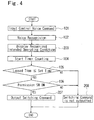
- Fig. 4 is a flow chart showing the process of controlling another onboard control system by a voice.
- the present invention is applied to the shift control of the automatic transmission, but the present invention should not be restricted to this.
- steps 203, 207 and 208 it is possible to control all the actions of the following onboard equipment by voices: a wiper, headlights, an air conditioner, an audio equipment, turn signal lamps, hazard lamps, select positions or over-drive switch of a multi-speed transmission, power seats, power windows, a room lamp, a watch, an ASCD (automatic speed control device) and so forth.
- a step 203 of the flow chart the operating condition as the intended action recognized in the controller 1 is displayed on the display unit 5.
- a command to switch the operating condition to the intended one is outputted to the subject onboard control system.
- the push-button type switch is used as the permission switch in the former embodiment, but the present invention should not be restricted to this.
- an up-down shift type switch or a grip switch which is turned on by gripping the steering wheel, may be used as the permission switch.
- the permission switch is provided on the steering wheel, but a foot switch (a switch which is pressed by a foot) may be used as the permission switch.
- the present invention may also be applied to control systems in barrier-free vehicles such as electric wheelchairs.
Landscapes
- Engineering & Computer Science (AREA)
- General Engineering & Computer Science (AREA)
- Mechanical Engineering (AREA)
- Control Of Transmission Device (AREA)
- Arrangement Or Mounting Of Control Devices For Change-Speed Gearing (AREA)
- Instrument Panels (AREA)
Abstract
A vehicle control device comprises: a microphone (3) for
inputting a driver's control command; a voice recognition unit
for recognizing a voice signal of the control command inputted
by the microphone; a display unit (5) for displaying the control
command recognized by the voice recognition unit; a control
permission unit (4) for permitting the control command to be outputted
in response to a permitting action taken by the driver who confirms
that what is displayed on the display unit conforms to the control
command intended by the driver; and an onboard control system for
performing a controlling operation according to the control
command outputted from the voice recognition unit by permission
of said control permission unit. Since the onboard control system
is controlled by the voice signal, the necessity of removing the
hand from the steering wheel is eliminated.
Description
- The present invention relates generally to a vehicle control device that controls onboard equipment. More particularly, the present invention relates to a shift control device of an automatic transmission, which is controlled by driver's voices.
- Japanese Patent Application Laid-open Publication No. 8-178000 discloses an example of conventional shift control devices of automatic transmissions. The shift control device disclosed in this publication has an automatic shift mode wherein a gear ratio of a continuously variable transmission is controlled to be a target gear ratio determined according to an operating state, and a manual mode which is set by shifting a shift lever to positions adjacent a D range, etc. and controls a gear ratio to a manually-set target gear ratio. The manual mode enables the shift to a gear ratio designated by the driver.
- According to the above prior art, however, when changing gear positions manually, a driver must remove his or her hand from a steering wheel and shift a shift lever to the manual mode. Thus, the driver has to move the shift lever forward and backward with a large stroke of the hand. Particularly if the steering wheel must be turned or the like frequently as in the case of sport driving, it is desirable to keep hands on the steering wheel as much as possible.
- The above problem is also encountered in a case where vehicle equipments such as an air conditioner temperature control device, a wiper and a headlight, which are operated by temporarily removing the hand from the steering wheel, are controlled.
- It is therefore an object of the present invention to provide a vehicle control device that enables a driver to control an onboard system without removing the hand from a steering wheel.
- To attain the above object, the present invention provides a vehicle control device comprising: a microphone for inputting a driver's control voice command; a voice recognition unit for recognizing a voice signal of the control command inputted by the microphone; a display unit for displaying the control command recognized by the voice recognition unit at such a position as to be seen by the driver; a control permission unit for permitting the control command to be outputted in response to a permitting action taken by the driver who confirms that what is displayed on the display unit conforms to the control command intended by the driver; and an onboard control system for performing a controlling operation according to the control command outputted from the voice recognition unit by permission of the control permission unit.
- According to the invention, the microphone inputs the driver's control command as a voice signal, and the voice recognition unit recognizes the voice signal inputted by said microphone. The display unit then displays the control command recognized by the voice recognition unit. The control permission unit permits the control command to be outputted in response to a permitting action taken by the driver who confirms that what is displayed on the display unit conforms to the intended control command. The onboard control system performs a controlling operation according to the control command outputted by permission.
- Thus, the onboard control system, which has been conventionally operated and controlled by using the hand, is controlled by the voice signal.
- This enables safety driving.
- Moreover, one control permission device enables multiple operations and controls, and this makes the structure compact.
- In one preferred form of the present invention, the vehicle control device further comprises: a timer that starts counting when or after the voice recognition unit recognizes the voice signal; and a control cancel means that does not output the control command if a preset time of said timer has elapsed without said permitting action taken by the driver.
- When the voice recognition unit recognizes an incorrect signal, the incorrectly-recognized signal is canceled without requiring the driver's operation, since the control command is not outputted if a preset time has elapsed without the permitting action taken by the driver.
- In another preferred form of the present invention, the control permission unit receives a signal of the permitting action taken by the driver from a permission switch provided on a steering wheel.
- This enables safely operation because the driver can operate the permission switch without removing the hand from the steering wheel.
- In yet another preferred form of the present invention, the onboard control system is a shift control system of an automatic transmission.
- In the case of the conventional automatic transmission, it is necessary to operate the shift lever when selecting the driver's intended shift position. According to this form, however, a shift position can be selected by a voice signal. Thus, the driver can safely perform a shifting operation without removing the hand from the steering wheel.
- The nature of this invention, as well as other objects and advantages thereof, will be explained in the following with reference to the accompanying drawings, in which like reference characters designate the same or similar parts throughout the figures and wherein:
- Fig. 1 is a block diagram showing the entire structure of a vehicle control device according to an embodiment of the present invention;
- Fig. 2 is a block diagram showing the structure of a principal unit in a vehicle equipped with a continuously variable transmission according to the embodiment of the present invention;
- Fig. 3 is a flow chart showing the process of controlling a shift by a voice according to the embodiment of the present invention; and
- Fig. 4 is a flow chart showing the process of controlling an onboard control system by a voice according to another embodiment of the present invention.
-
- Preferred embodiments of the present invention will be described hereinbelow with reference to the accompanying drawings.
- Fig. 1 is a block diagram showing the embodiment applied to a control device of a belt-type continuously variable transmission (hereinafter referred to as CVT) .
- The vehicle control device has a
microphone 3, a push-buttontype permission switch 4 provided on a steering wheel and adisplay unit 5 provided on a meter panel, which are all connected to a controller 1. - The controller 1 comprises a voice recognition unit and a control permission unit therein and is connected to a
CVT control unit 14. - The
microphone 3 inputs a driver's voice. In a controller 1 the voice recognition unit recognizes the voice inputted from themicrophone 3. A control command recognized by the voice recognition unit is outputted from the controller 1 to thedisplay unit 5. Thedisplay unit 5 displays the present operating condition of the belt-type CVT and also displays the next action by lighting. Thepermission switch 4 on the steering wheel is operated by the driver who permits the action displayed on thedisplay unit 5. TheCVT control unit 14 controls a shifting operation according to a control command, which is outputted from the controller 1 responding to the operation of thepermission switch 4. - Fig. 2 is a diagram showing a control system of the belt-type CVT.
- An output shaft of an engine (not shown) connects to the
torque converter 20 serving as a rotation transmission mechanism. In thetorque converter 20, thelockup clutch 21 is provided which directly connects the engine with the belt-type CVT 2 when engaged. - An output side of the
torque converter 20 connects to atransmission input shaft 26. Primary pulleys 27, 28 of the belt-type CVT 2 are provided at the end of theinput shaft 26. - The belt-type CVT 2 has the primary pulleys 27, 28;
secondary pulleys belt 31 that transmits the torques from the primary pulleys 27, 28 to thesecondary pulleys input shaft 26 due to primary hydraulic pressure applied to a primarypulley cylinder chamber 32, and thepulley 30 is capable of moving along theoutput shaft 34 due to the secondary hydraulic pressure applied to a secondarypulley cylinder chamber 33. A drive gear (not shown) is secured to theoutput shaft 34, and drives a drive shaft that reaches driving wheels via a pinion provided on an idler shaft, a final gear and a differential gear unit. - A rotational ratio between the primary pulleys 27, 28 and the
secondary pulleys pulleys 28, 30 axially thereby changing the radius of a contact area between the primary and secondary pulleys and thebelt 31. In this controlling operation, the widths of V-shaped grooves on the primary pulleys 27, 28 and thesecondary pulleys pressure control valve 15 according to an instruction from theCVT control unit 14 and then supplying these hydraulic pressures to the primarypulley cylinder chamber 32 and the secondarypulley cylinder chamber 33. - The
CVT control unit 14 receives a throttle opening signal from the throttle opening sensor 9, a switch signal from akickdown switch 35, a vehicle speed signal from avehicle speed sensor 36, a transmission oil temperature signal from an oil temperature sensor 37, a primary revolutionary speed signal from the primaryrevolutionary speed sensor 22, a secondary revolutionary speed signal from the secondaryrevolutionary speed sensor 23, and other signals. The throttle opening sensor 9 detects the opening of the throttle valve which is driven by the accelerator pedal. According to these input signals, theCVT control unit 14 performs an arithmetic operation to output a line pressure control signal to theline pressure solenoid 24, output a gear ratio control signal to the hydraulicpressure control valve 15 and output an oil pump unit control signal to theoil pump unit 25. - Fig. 3 is a flow chart showing the process of controlling the shifting operation of the belt-type CVT according to the embodiment. There will now be described the process of controlling the belt-type CVT by a voice with reference to the flow chart.
- In a
step 101, a driver's shift intention is inputted as the voice signal from the microphone to the controller 1. - In a
step 102, in the controller, the input voice signal is recognized by the voice recognition unit as a control command. - In a step 103, the control command, in other words, the intended action such as a shifting gear position, recognized in the controller 1 is displayed on the
display unit 5. - In a
step 104, a timer starts counting. - In a
step 105, the controller 1 determines whether an elapsed time is within a set-up time of the timer or not. If the determination is positive (yes), the process goes to astep 106. If the determination is negative (no), the process goes to astep 108 without outputting a shift command. - In the
step 106, it is determined in the controller 1 whether thepermission switch 4 is ON or OFF. If thepermission switch 4 is ON, the process goes to astep 107. If thepermission switch 4 is OFF, the process goes to thestep 108 without outputting a shift command. - In the
step 107, a shift command as the intended action is outputted to theCVT control unit 14 to carry out a shifting operation. - More specifically, when the driver inputs the shift intention to the
microphone 3 by his or her voice, the recognized gear position is displayed so as to confirm whether the driver's intention is correctly recognized or not. The timer then starts counting. Thus, if the driver has no intention of shifting or if the action is falsely recognized, the display of the gear position is ignored and is automatically invalidated if the preset time of the timer has elapsed. If thepermission switch 4 provided on the steering wheel is turned on the shift command is outputted to theCVT control unit 14. Accordingly, the shifting operation is carried out. - As stated above, the driver controls the shifting operation by his or her voice, and therefore, the driver does not have to remove the hands from the steering wheel during the shifting operation even if the steering wheel must be turned frequently as in the case of sport driving. Moreover, the use of
permission switch 4 prevents the output of an incorrect shift command if the controller 1 falsely recognizes the action. Consequently, the shifting operation can be carried out without fail in accordance with the driver's intention. - Fig. 4 is a flow chart showing the process of controlling another onboard control system by a voice.
- As stated above, the present invention is applied to the shift control of the automatic transmission, but the present invention should not be restricted to this. For example, incorporating
steps - In a
step 203 of the flow chart, the operating condition as the intended action recognized in the controller 1 is displayed on thedisplay unit 5. - And, in a
step 207, a command to switch the operating condition to the intended one is outputted to the subject onboard control system. - Moreover, the push-button type switch is used as the permission switch in the former embodiment, but the present invention should not be restricted to this. For example, an up-down shift type switch or a grip switch, which is turned on by gripping the steering wheel, may be used as the permission switch.
- Furthermore, the permission switch is provided on the steering wheel, but a foot switch (a switch which is pressed by a foot) may be used as the permission switch.
- In addition, the present invention may also be applied to control systems in barrier-free vehicles such as electric wheelchairs.
- It should be understood, however, that there is no intention to limit the invention to the specific forms disclosed, but on the contrary, the invention is to cover all modifications, alternate constructions and equivalents falling within the spirit and scope of the invention as expressed in the appended claims.
Claims (6)
- A vehicle control device comprising:a microphone for inputting a driver's control voice command;a voice recognition unit for recognizing a voice signal of the control command inputted by said microphone;a display unit for displaying the control command recognized by said voice recognition unit at such a position as to be seen by the driver;a control permission unit for permitting the control command to be outputted in response to a permitting action taken by the driver who confirms that what is displayed on said display unit conforms to the control command intended by the driver; andan onboard control system for performing a controlling operation according to the control command outputted from said voice recognition unit by permission of said control permission unit.
- A vehicle control device according to claim 1, further comprising:a timer that starts counting when or after said voice recognition unit recognizes said voice signal; anda control cancel means that does not output the control command if a preset time of said timer has elapsed without said permitting action taken by the driver.
- A vehicle control device according to claim 1 or claim 2, wherein:said control permission unit receives a signal of said permitting action taken by the driver from a permission switch provided on a steering wheel.
- A vehicle control device according to claim 1, 2 or 3, wherein:said onboard control system is a shift control system of an automatic transmission.
- Control apparatus for controlling operation of a vehicle, the control apparatus comprising:transducer means (3) for detecting a voice command of an operator of such a vehicle and outputting a signal based on the voice command; voice recognition means (1) for recognising said signal and outputting a control command signal; output means (5) for outputting the control command signal to such an operator for verification thereby; and control means (1) for controlling an operation according to said control command signal when verification is received.
- A vehicle comprising the vehicle control device as claimed in claims 1 to 4 or the control apparatus claimed in claim 5.
Applications Claiming Priority (2)
| Application Number | Priority Date | Filing Date | Title |
|---|---|---|---|
| JP2000195426 | 2000-06-29 | ||
| JP2000195426A JP2002012100A (en) | 2000-06-29 | 2000-06-29 | Vehicle control device |
Publications (1)
| Publication Number | Publication Date |
|---|---|
| EP1172585A2 true EP1172585A2 (en) | 2002-01-16 |
Family
ID=18694088
Family Applications (1)
| Application Number | Title | Priority Date | Filing Date |
|---|---|---|---|
| EP01305674A Withdrawn EP1172585A2 (en) | 2000-06-29 | 2001-06-29 | Vehicle control device |
Country Status (3)
| Country | Link |
|---|---|
| US (1) | US20020128762A1 (en) |
| EP (1) | EP1172585A2 (en) |
| JP (1) | JP2002012100A (en) |
Cited By (5)
| Publication number | Priority date | Publication date | Assignee | Title |
|---|---|---|---|---|
| EP1342605A1 (en) | 2002-03-04 | 2003-09-10 | Ford Global Technologies, Inc., A subsidiary of Ford Motor Company | Device for controlling a screen display |
| US7189992B2 (en) | 2002-05-21 | 2007-03-13 | State Of Oregon Acting By And Through The Oregon State Board Of Higher Education On Behalf Of Oregon State University | Transistor structures having a transparent channel |
| CN107199971A (en) * | 2017-05-03 | 2017-09-26 | 深圳车盒子科技有限公司 | Vehicle-mounted voice exchange method, terminal and computer-readable recording medium |
| DE10327438B4 (en) * | 2002-06-21 | 2020-04-02 | Schaeffler Technologies AG & Co. KG | Method for controlling and / or regulating a clutch |
| WO2026013010A1 (en) * | 2024-07-09 | 2026-01-15 | Aumovio Germany Gmbh | Method for operating a (partially) autonomously operating control unit of a vehicle, vehicle control system and vehicle |
Families Citing this family (18)
| Publication number | Priority date | Publication date | Assignee | Title |
|---|---|---|---|---|
| JP2003021231A (en) * | 2001-07-10 | 2003-01-24 | Fujitsu Ten Ltd | Control device for automatic transmission |
| KR20040035151A (en) * | 2002-10-18 | 2004-04-29 | 현대모비스 주식회사 | Speech recognition apparatus for vehicle and operating method thereof |
| KR100527512B1 (en) * | 2002-12-13 | 2005-11-09 | 현대자동차주식회사 | Method and system for interfacing controling an electronic apparatus of a vehicle |
| US7624019B2 (en) * | 2005-10-17 | 2009-11-24 | Microsoft Corporation | Raising the visibility of a voice-activated user interface |
| US7962268B2 (en) * | 2007-05-21 | 2011-06-14 | Samuel Seungmin Cho | Method and apparatus for manual-mode shifting using voice commands in automobile transmissions |
| US8065063B2 (en) * | 2007-05-22 | 2011-11-22 | Samuel Seungmin Cho | Method and apparatus to shift-by-speech for semi-manual transmissions with intelligent shifting algorithm |
| JP2009248629A (en) * | 2008-04-02 | 2009-10-29 | Hitachi Ltd | Input device of on-vehicle apparatus and input method of on-vehicle apparatus |
| GB2505022B (en) * | 2012-08-16 | 2015-01-14 | Jaguar Land Rover Ltd | Speed control system and method for operating the same |
| WO2015128960A1 (en) | 2014-02-26 | 2015-09-03 | 三菱電機株式会社 | In-vehicle control apparatus and in-vehicle control method |
| DE102015200522B4 (en) | 2015-01-15 | 2022-03-31 | Ford Global Technologies, Llc | Method for supporting a maneuvering process of a motor vehicle and driver assistance system |
| CN107757626A (en) * | 2016-08-19 | 2018-03-06 | 上汽通用汽车有限公司 | A kind of acoustic control shifting control system |
| JP7193957B2 (en) * | 2018-09-12 | 2022-12-21 | カワサキモータース株式会社 | Vehicle setting change system |
| JP7087919B2 (en) | 2018-10-31 | 2022-06-21 | トヨタ自動車株式会社 | Driving Assistance Equipment, Vehicles, Driving Assistance Methods and Programs |
| KR102764258B1 (en) * | 2018-12-03 | 2025-02-07 | 현대자동차주식회사 | Apparatus for processing voice command in vehicle and method thereof |
| CN109812575B (en) * | 2019-01-31 | 2020-09-08 | 吉林微思智能科技有限公司 | Knob type automobile gear shifting system with voice recognition function and voice awakening recognition method |
| JP7261626B2 (en) * | 2019-03-19 | 2023-04-20 | 本田技研工業株式会社 | VEHICLE EQUIPMENT CONTROL SYSTEM, VEHICLE EQUIPMENT CONTROL DEVICE, VEHICLE EQUIPMENT CONTROL METHOD, AND PROGRAM |
| JP7243567B2 (en) * | 2019-10-18 | 2023-03-22 | トヨタ自動車株式会社 | Change operation support device |
| CN114162216B (en) * | 2022-01-12 | 2023-04-25 | 大运汽车股份有限公司 | Voice-assisted steering multi-mode switching control method |
-
2000
- 2000-06-29 JP JP2000195426A patent/JP2002012100A/en active Pending
-
2001
- 2001-06-27 US US09/892,278 patent/US20020128762A1/en not_active Abandoned
- 2001-06-29 EP EP01305674A patent/EP1172585A2/en not_active Withdrawn
Cited By (6)
| Publication number | Priority date | Publication date | Assignee | Title |
|---|---|---|---|---|
| EP1342605A1 (en) | 2002-03-04 | 2003-09-10 | Ford Global Technologies, Inc., A subsidiary of Ford Motor Company | Device for controlling a screen display |
| US7189992B2 (en) | 2002-05-21 | 2007-03-13 | State Of Oregon Acting By And Through The Oregon State Board Of Higher Education On Behalf Of Oregon State University | Transistor structures having a transparent channel |
| US7888207B2 (en) | 2002-05-21 | 2011-02-15 | State of Oregon Acting by and through the Oregon State Board of Higher Eduacation on behalf of Oregon State University | Transistor structures and methods for making the same |
| DE10327438B4 (en) * | 2002-06-21 | 2020-04-02 | Schaeffler Technologies AG & Co. KG | Method for controlling and / or regulating a clutch |
| CN107199971A (en) * | 2017-05-03 | 2017-09-26 | 深圳车盒子科技有限公司 | Vehicle-mounted voice exchange method, terminal and computer-readable recording medium |
| WO2026013010A1 (en) * | 2024-07-09 | 2026-01-15 | Aumovio Germany Gmbh | Method for operating a (partially) autonomously operating control unit of a vehicle, vehicle control system and vehicle |
Also Published As
| Publication number | Publication date |
|---|---|
| US20020128762A1 (en) | 2002-09-12 |
| JP2002012100A (en) | 2002-01-15 |
Similar Documents
| Publication | Publication Date | Title |
|---|---|---|
| US20020128762A1 (en) | Vehicle control device | |
| US6821228B2 (en) | Control apparatus for continuously variable transmission | |
| US6145399A (en) | Indicator for a shift by wire vehicle transmission | |
| EP0832778B1 (en) | Control apparatus for clutch of vehicle | |
| US6908412B2 (en) | Control apparatus for continuously variable transmission | |
| EP2126418A2 (en) | Shift control apparatus for vehicular continuously variable transmissions | |
| US6547691B2 (en) | Shift control system for continuously variable transmission | |
| JP3949345B2 (en) | Control method for continuously variable transmission | |
| US6105453A (en) | Control system for automatic vehicle transmission with separate range selector solely for establishing parking range | |
| JP2002243031A (en) | Transmission control device for automatic transmission | |
| JP2002168339A (en) | Transmission control device | |
| DE50308267D1 (en) | Device and method for controlling an automated gearbox of a motor vehicle | |
| JP4929724B2 (en) | Engine brake compensation controller for vehicles with automatic transmission | |
| JP4535521B2 (en) | Control device for automatic transmission | |
| KR100495440B1 (en) | Auto-transmission control system for vehicle | |
| JPH09250636A (en) | Display device for vehicles | |
| JP4810882B2 (en) | Control device for vehicles with automatic transmission | |
| JPH0419463A (en) | Continuously variable transmission control device for vehicle | |
| JPH02229922A (en) | Clutch controller and method | |
| JP2002188720A (en) | Continuously variable transmission | |
| JPH03258931A (en) | Automatic variable speed control device | |
| JPH04194451A (en) | Automatic speed change control device | |
| JP2001140950A (en) | Automatic clutch control device | |
| JPH08324297A (en) | Control method of automatic transmission | |
| JPH07280054A (en) | Auxiliary drive continuously variable transmission |
Legal Events
| Date | Code | Title | Description |
|---|---|---|---|
| PUAI | Public reference made under article 153(3) epc to a published international application that has entered the european phase |
Free format text: ORIGINAL CODE: 0009012 |
|
| AK | Designated contracting states |
Kind code of ref document: A2 Designated state(s): AT BE CH CY DE DK ES FI FR GB GR IE IT LI LU MC NL PT SE TR |
|
| AX | Request for extension of the european patent |
Free format text: AL;LT;LV;MK;RO;SI |
|
| RAP1 | Party data changed (applicant data changed or rights of an application transferred) |
Owner name: JATCO LTD |
|
| STAA | Information on the status of an ep patent application or granted ep patent |
Free format text: STATUS: THE APPLICATION IS DEEMED TO BE WITHDRAWN |
|
| 18D | Application deemed to be withdrawn |
Effective date: 20040103 |