EP1172550A2 - A water drain valve - Google Patents
A water drain valve Download PDFInfo
- Publication number
- EP1172550A2 EP1172550A2 EP01305378A EP01305378A EP1172550A2 EP 1172550 A2 EP1172550 A2 EP 1172550A2 EP 01305378 A EP01305378 A EP 01305378A EP 01305378 A EP01305378 A EP 01305378A EP 1172550 A2 EP1172550 A2 EP 1172550A2
- Authority
- EP
- European Patent Office
- Prior art keywords
- water drain
- drain valve
- flow
- valve
- water
- Prior art date
- Legal status (The legal status is an assumption and is not a legal conclusion. Google has not performed a legal analysis and makes no representation as to the accuracy of the status listed.)
- Granted
Links
- XLYOFNOQVPJJNP-UHFFFAOYSA-N water Substances O XLYOFNOQVPJJNP-UHFFFAOYSA-N 0.000 title claims abstract description 89
- 238000007789 sealing Methods 0.000 claims abstract description 51
- 239000000446 fuel Substances 0.000 claims abstract description 19
- 238000004891 communication Methods 0.000 claims abstract description 8
- 238000000926 separation method Methods 0.000 claims abstract description 6
- 238000005266 casting Methods 0.000 abstract description 2
- 238000010276 construction Methods 0.000 description 8
- 230000006835 compression Effects 0.000 description 7
- 238000007906 compression Methods 0.000 description 7
- 230000008901 benefit Effects 0.000 description 4
- 238000013022 venting Methods 0.000 description 4
- 239000007788 liquid Substances 0.000 description 2
- 238000012986 modification Methods 0.000 description 2
- 230000004048 modification Effects 0.000 description 2
- 230000000717 retained effect Effects 0.000 description 2
- 230000009471 action Effects 0.000 description 1
- 230000004075 alteration Effects 0.000 description 1
- 230000008859 change Effects 0.000 description 1
- 150000001875 compounds Chemical class 0.000 description 1
- 230000000694 effects Effects 0.000 description 1
- 230000006870 function Effects 0.000 description 1
- 238000009434 installation Methods 0.000 description 1
- 230000014759 maintenance of location Effects 0.000 description 1
- 239000000463 material Substances 0.000 description 1
- 230000013011 mating Effects 0.000 description 1
- 230000001737 promoting effect Effects 0.000 description 1
- 229920002994 synthetic fiber Polymers 0.000 description 1
Images









Classifications
-
- B—PERFORMING OPERATIONS; TRANSPORTING
- B01—PHYSICAL OR CHEMICAL PROCESSES OR APPARATUS IN GENERAL
- B01D—SEPARATION
- B01D36/00—Filter circuits or combinations of filters with other separating devices
- B01D36/003—Filters in combination with devices for the removal of liquids
- B01D36/006—Purge means
-
- B—PERFORMING OPERATIONS; TRANSPORTING
- B01—PHYSICAL OR CHEMICAL PROCESSES OR APPARATUS IN GENERAL
- B01D—SEPARATION
- B01D19/00—Degasification of liquids
- B01D19/0063—Regulation, control including valves and floats
-
- Y—GENERAL TAGGING OF NEW TECHNOLOGICAL DEVELOPMENTS; GENERAL TAGGING OF CROSS-SECTIONAL TECHNOLOGIES SPANNING OVER SEVERAL SECTIONS OF THE IPC; TECHNICAL SUBJECTS COVERED BY FORMER USPC CROSS-REFERENCE ART COLLECTIONS [XRACs] AND DIGESTS
- Y10—TECHNICAL SUBJECTS COVERED BY FORMER USPC
- Y10T—TECHNICAL SUBJECTS COVERED BY FORMER US CLASSIFICATION
- Y10T137/00—Fluid handling
- Y10T137/8593—Systems
- Y10T137/86292—System with plural openings, one a gas vent or access opening
- Y10T137/86324—Tank with gas vent and inlet or outlet
- Y10T137/86332—Vent and inlet or outlet in unitary mounting
-
- Y—GENERAL TAGGING OF NEW TECHNOLOGICAL DEVELOPMENTS; GENERAL TAGGING OF CROSS-SECTIONAL TECHNOLOGIES SPANNING OVER SEVERAL SECTIONS OF THE IPC; TECHNICAL SUBJECTS COVERED BY FORMER USPC CROSS-REFERENCE ART COLLECTIONS [XRACs] AND DIGESTS
- Y10—TECHNICAL SUBJECTS COVERED BY FORMER USPC
- Y10T—TECHNICAL SUBJECTS COVERED BY FORMER US CLASSIFICATION
- Y10T137/00—Fluid handling
- Y10T137/8593—Systems
- Y10T137/86493—Multi-way valve unit
- Y10T137/86863—Rotary valve unit
- Y10T137/86871—Plug
Definitions
- the present invention relates in general to fuel filters with a water separation capability and the cooperating components and subassemblies used with such fuel filters. More specifically the present invention relates to the design of a water drain valve for draining accumulated water from within a fuel filter which is designed with a water separation capability.
- a drain includes the flow passageway from the filter housing into the drain valve and the outlet passageway or aperture of the drain valve which empties the draining water from the drain valve.
- the structural remainder of the drain valve controls the flow of water from the flow passageway of the filter housing to the outlet passageway of the drain valve. Venting air is introduced by the drain valve as the water empties.
- the present invention provides the novel design of a water drain valve which takes into consideration each of these important considerations.
- the water drain valve of the present invention provides a vented, water drain valve which is suitable for use in both non-pressurized and pressurized configurations without the unwanted spillage of fuel.
- the water drain valve of the present invention is also designed without the added cost of a check valve.
- a water drain valve for use in cooperation with a fuel filter having a water separation capability comprises a valve housing having a sidewall defining a first flow aperture therethrough and a second flow aperture therethrough and further defining a hollow interior extending into a drain opening, a flow-control piston positioned within the hollow interior and including a first portion defining a water drain passageway leading to the drain opening and a second portion defining an air flow passageway leading from the drain opening, a first sealing grommet assembled into the first flow aperture and having a sidewall defining a water flow path into the drain valve and being constructed and arranged to sealingly engage the first portion, a second sealing grommet assembled into the second flow aperture and having a sidewall defining an air flow path from the drain valve and being constructed and arranged to sealingly engage the second portion, and a spring biased control lever assembled to the valve housing and being constructed and arranged to rotate the flow-control piston from a drain valve normally-closed condition wherein the water flow path through the first sealing grommet is
- One object of the present invention is to provide an improved water drain valve for use with a fuel filter.
- FIG. 1 is a perspective view of the drain valve 20 in its normally-closed condition which coincides with the FIG. 2 top plan view.
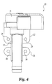
- FIG. 3 is a top plan view of the drain valve 20 in its open condition which coincides with the FIG. 4 front elevational view.
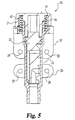
- the sectioning plane 5-5 view drawn in FIG. 2 is illustrated in FIG. 5 as a front elevational view of the drain valve 20 in full section in the normally-closed condition.
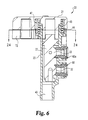
- the view at 90 degrees is created from the sectioning plane 6-6 view in FIG. 2 as illustrated in FIG. 6 as a side elevational view of the drain valve 20 in full section in the normally-closed condition.
- FIG. 7 is included.
- FIG. 7 is a front elevational view in full section corresponding to FIG. 6, but with the control lever 21 turned 90 degrees (see FIG. 3) so as to rotate the interior, flow-control piston 22 within outer housing 23 to place the drain valve 20 into its valve-open condition.
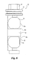
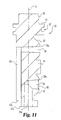
- the details of the interior flow-control piston 22 are illustrated in FIGS. 8-11.
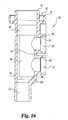
- the details of the outer housing 23 are illustrated in FIGS. 12-16.
- the details of control lever 21 are illustrated in FIGS. 17-20.
- the drain valve 20 includes a construction by which the flow-control piston 22 cooperates with the interior features and construction of the outer housing in order to provide a functioning drain valve which is in a normally-closed condition or orientation.
- An air vent feature is included as part of drain valve 20 and the opening or closing of the water drain passageway coincides with the opening or closing of the air vent passageway, respectively.
- the control lever 21 is assembled in a spring-biased manner such that when manually moved from its normally-closed position to the valve-open position, the release of manual force on the control lever allows it to return automatically (spring return) to the normally-closed position.
- the control lever 21 is cooperatively coupled to the piston 22 in order to rotate the piston 22 relative to the stationary outer housing 23 and thereby change the condition of the drain valve 20 from closed to open.
- Mounting provisions in the form of brackets 26 and 27 and clearance holes 28 and 29, respectively, are included as part of the outer housing 23.
- the outer housing is a unitary casting and the brackets 26 and 27 are cast as part of this unitary construction. If synthetic materials are used for the outer housing 23, then a molded unitary construction is contemplated, still including the two mounting brackets 26 and 27 as part of this unitary construction.
- the drain valve 20 is constructed and arranged for attachment to a fuel filter housing for draining accumulated water from the interior of the fuel filter housing.
- Piston 22 of drain valve 20 is illustrated as a unitary member which is preferably cast. As an alternative, a molded construction is contemplated, but still as a unitary member.
- Piston 22 includes two part-spherical sections 32 and 33 which are positioned on opposite sides of alignment portion 34. These two sections 32 and 33 are described as being “part” spherical due to the flatted face 32a on section 32 and the flatted face 33a on section 33 into which flow passageways 35 and 36, respectively, are created.
- Flow passageway 35 extends into face 32a of section 32 and provides part of the water drain path for water drain valve 20.
- the remainder of the water drain path through the piston 22 is provided by connecting passageway 35a.
- Flow passageway 36 extends into face 33a of section 33 and provides part of the air vent path through water drain valve 20.
- the remainder of the air vent path through the piston is provided by connecting passageway 36a.
- FIG. 11 full section view corresponds to the orientation of piston 22 in FIGS. 5 and 7.
- the piston 22 is turned (rotated) so as to close off both the water drain and air vent passageways that extend through the wall of the outer housing 23.
- the piston flow passageways 35 and 36 line up with the water drain and air vent passageways of the outer housing 23.
- Annular channel 37 is sized and arranged to receive an O-ring 38 for sealing between piston 22 and outer housing 23 (see FIG. 7).
- outer housing 23 is a unitary structure which includes mounting brackets 26 and 27 and a wall portion 39 defining a hollow interior 40.
- the FIG. 16 view corresponds to the orientation of outer housing 23 as illustrated in assembly FIGS. 6 and 7 for drain valve 20.
- the drain passageway 41 which is defined by wall portion 39 has a generally cylindrical, stepped form.
- the air vent passageway 42 which is also defined by wall portion 39, has a generally cylindrical, stepped form. Both passageways 41 and 42 extend into and are in flow communication with hollow interior 40.
- outlet passageway 43 which is used to drain the water that enters the drain valve by way of passageway 41.
- Outlet passageway 43 also provides a path for venting air to enter the drain valve 20 and ultimately enter the fuel filter housing by way of passageway 42.
- Annular channel 44 in housing 23 receives part (i.e., the lower end) of helical torsion spring 45 (see FIGS. 5, 6, and 7) and the open upper end 46 receives a portion of control lever 21.
- the control lever also includes an annular channel 47 which axially aligns with channel 44 to receive the remainder (i.e., the upper end) of helical torsion spring 45.
- FIGS. 1-7 also include views of the control lever 21.
- D-shaped sleeve 51 fits over the upper, generally D-shaped portion 52 of piston 22.
- the D-shaped design for sleeve 51 and for cooperating portion 52 establishes a fixed rotational relationship and a driver-driven relationship between the sleeve 51 and portion 52.
- Rotation of the lever 21 causes and controls rotation of piston 22.
- spring 45 helps to maintain the desired axial position and relationship between the lever 21 and the piston 22 and housing 23, there is an interfit between lever 21 and housing 23 which helps to maintain the flow-control piston 22 in somewhat of a floating and self-centering arrangement.
- FIGS. 21, 22, and 23 a sealing grommet 60 having the form of an annular sleeve is illustrated.
- a total of two virtually identical sealing grommets 60 and 60a are used in the FIG. 1 water drain valve 20.
- Each sealing grommet 60 and 60a is fabricated from a compressible, resilient rubber compound so as to facilitate the creation of a sealed interface against the fuel filter housing.
- Reference herein to grommet 60 or aspects of grommet 60 will include grommet 60a, unless these two need to be differentiated due to their different locations in the valve assembly.
- the material for the two sealing grommets also facilitates the creation of a sealed interface around the water flow passageway 35 in part-spherical section 32 and around the air flow passageway 36 in part-spherical section 33.
- each sealing grommet 60 is inserted into drain passageway 41 and the other sealing grommet 60a is inserted into air vent passageway 42. As illustrated in FIGS. 6 and 7, the radiused outer edge 61 of each sealing grommet extends beyond the outer surface 62 of wall portion 39.
- the annular outer edge 61 of each grommet 60 and 60a is compressed so as to create a sealed interface around each passageway 41 and 42, respectively, between the drain valve housing and the fuel filter housing.
- the end 63 of each grommet 60 and 60a which is opposite to outer edge 61, extends into the hollow interior 40 of the outer housing 23 beyond the inner surface 64 which helps to define the hollow interior 40.
- the outermost surface 65 of end 63 is substantially flat with a rounded outer annular corner 66 and a rounded inner annular corner 67.
- the two part-spherical sections 32 and 33 of piston 22 are constructed and arranged to mate with and rotate within the end 63 of each grommet 60 and 60a, respectively. Dimensioning this sealing arrangement or interface can be a problem due to the stack up of the tolerances on the various dimensions of the piston 22, sealing grommets 60 and 60a, and housing 23.
- the piston 22 must be located so that the part-spherical sections 32 and 33 will align with each corresponding sealing grommet 60 and 60a.
- the compression of the sealing grommets 60 and 60a must be controlled so as to be sufficient for sealing, but not so great as to cause undue rotational friction when the lever 21 and piston 22 are turned and the drain valve is opened (or closed).
- the proposed valve 20 removes the inherent axial tolerance stack-up in the assembly of piston 22, housing 23, and sealing grommets 60 and 60a by the addition of a unique alignment portion 34 that is dimensioned directly from the centerline of each part-spherical section 32 and 33.
- This portion 34 contacts each sealing grommet 60 and 60a in a radial manner, only if an axial force is applied to the piston 22.
- This dimensional relationship uses only the centerline location (i.e., spacing) of the sealing grommet 60 and 60a in the housing 23, the diameter of each sealing grommet 60 and 60a, the location of the part-spherical sections 32 and 33, and the radial distance to the top and bottom surfaces 34a and34b, respectively, of portion 34.
- Small clearance spaces 77 and 78 are provided to allow a primary location of the part-spherical sections 32 and 33 by interfacing with the cylindrical ends 63 of the sealing grommets 60 and 60a.
- This arrangement provides a much tighter control than by possibly using the bottom surface 22b of the piston 22 against the bottom surface 39a of the housing 23 in combination with an upper surface 53 of the piston 22 against the bottom of an inserted ring to limit the axial travel.
- Piston 22 is permitted to float freely in an axial direction, thereby allowing the primary self-alignment or self-centering to be between the part-spherical sections 32 and 33 and the sealing grommets 60 and 60a.
- the lever 21 is separated from the piston 22.
- a unique, tapered, cantilever snap arrangement 73 between the lever 21 and housing 23 retains the lever 21 to the valve 20 without fastening it to the piston 22, see FIGS. 24, 25, and 26.
- Rotational engagement between the valve 20 and the lever 21 is made by the loose fitting combination of D-shaped sleeve 51 and D-shaped portion 52.
- each snap 79 and 80 is formed with a small hook 82 on the end that hooks into a radial slot 83 in the underside of the spring housing 81.
- This slot 83 also provides a drain for liquids or other debris that may find their way into the spring cavity 84 or into the annular channel 44.
- a stepped boss 85 on the lever 21 mates with two stepped bearing surfaces 86 and 87 in the top of the housing 23.
- an axial pitch is introduced into the helical torsion spring 45. This provides a slight axial force to take the play out of the drain valve 20, by pulling the snaps 79 and 80 tightly into the slot 83 and the bottom of the spring housing 81.
- the outer edges 90 and 91 of the passageways 35 and 36, respectively, that intersect with the surfaces 92 and 93 of the part-spherical sections 32 and 33, respectively, to provide flow for water and air are rounded to prevent cutting of the sealing grommets 60 and 60a (see FIG. 9).
- the larger diameter of the liquid passageway 35 allows grommet 60 to protrude into the passageway 35 as the passageway 35 passes the grommet 60 during valve 20 operation. This situation can cause the valve 20 to stick in the open position (see FIG. 7) and possibly damage the grommet 60.
- the leading edge 94 of the passageway 35 in the closing direction of the valve is relieved with a generous relief 95, giving the opening of the passageway 35 a teardrop shape. Maintaining the original diameter while relieving the leading edge 94 minimizes any tendency of grommet 60 to sink into the piston 22, by providing the maximum allowable support.
- the design for the sealing grommets 60 and 60a is unique in several ways.
- the grommets align with their mating part-spherical sections 32 and 33 with a type of ball and socket effect.
- they provide an axial retention and self-centering feature to the assembly due to their relationship with portion 34 on the piston.
- they are stepped at annular shoulder 60b to prevent improper assembly and provide a means of adjustment for compression against the piston 22.
- Shoulder 60b establishes the dividing line between smaller diameter section 60c and the larger diameter section 60d.
- they provide alignment for the assembly of the valve 20 to the filter housing.
- the grommets 60 and 60a serve to isolate all fuel from the inside of the valve 20 when the valve 20 is closed.
- each sealing grommet is compressed relative to its own axis. This compression is possible by providing a stepped cylindrical cavity, i.e., passageways 41 and 42, for each grommet 60 and 60a, respectively, in the housing 23 that is shorter in length than the length of each grommet. It is desired that the outer edge 61 of each grommet that mates with the filter housing (not shown) act as a seal for the valve outer housing 23 to the filter housing interface. This requires a certain amount of compression to overcome the internal pressure of the fuel system. The sealing grommets also must provide adequate sealing against the piston 22 without causing undue friction that might cause the valve 20 to stick in the open position.
- the overall amount of compression can be adjusted by adjusting the overall length of the grommets 60 and 60a relative to the depth or length of passageways 41 and 42 in the housing 23. Furthermore, the stepped design of each passageway 41 and 42, noting stepped edge 101 in each, enables the design of this embodiment to maintain a higher compressive force between the valve housing and the filter housing by isolating a portion of the resulting axial force of the interference at the valve housing to the filter housing interface. Stepped edge 101 coincides with shoulder 60b of each grommet. By moving the depth of this step 101 deeper or shallower in the passageways 41 and 42 and by adjusting the amount of compression in that area, the sealing force of the opposing ends of the grommets 60 and 60a can be adjusted for their particular function in the assembly.
- One benefit of embodiments of the present invention is the provision of a floating piston design that is free from the lever and that is therefore free to be located and retained by the sealing grommets 60 and 60a.
- Another benefit is the snap-fit lever with snaps on the one side, retained by the locking action of the hook shaped snaps into a slot that also serves to drain the spring cavity, limited in rotation perpendicular to the axis of the piston by radial plain bearings (not shown) and made virtually rattle free by an axially pitched helical torsion spring.
- the teardrop shaped relief on the edge of the drain passage is considered an advantage.
- the unique, stepped cylindrical grommets that form a ball and socket with the spherical sections of the piston, while preventing improper installation and providing a way to adjust the sealing force are also considered advantageous.
Landscapes
- Chemical & Material Sciences (AREA)
- Chemical Kinetics & Catalysis (AREA)
- Self-Closing Valves And Venting Or Aerating Valves (AREA)
- Multiple-Way Valves (AREA)
- Taps Or Cocks (AREA)
- Sliding Valves (AREA)
- Preventing Unauthorised Actuation Of Valves (AREA)
- Feeding And Controlling Fuel (AREA)
- Details Of Valves (AREA)
Abstract
Description
Claims (17)
- A water drain valve for use in cooperation with a fuel filter having a water separation capability, said water drain valve comprising:a valve housing having a sidewall defining a first flow aperture therethrough and a second flow aperture therethrough and further defining a hollow interior extending into a drain opening;a flow-control piston positioned within said hollow interior and including a first portion defining a water drain passageway leading to said drain opening and a second portion defining an air flow passageway leading from said drain opening;a first sealing grommet assembled into said first flow aperture, said first sealing grommet having a sidewall defining a water flow path into said water drain valve and being constructed and arranged to sealingly engage said first portion;a second sealing grommet assembled into said second flow aperture, said second sealing grommet having a sidewall defining an air flow path out of said water drain valve and being constructed and arranged to sealingly engage said second portion; anda control lever assembled to said valve housing and being constructed and arranged to rotate said flow-control piston from a water drain valve normally-closed condition wherein flow communication between said water flow path and said water drain passageway is closed and flow communication between said air flow passageway and said air flow path is closed to a water drain valve open condition wherein said water drain passageway is aligned with and in flow communication with said water flow path and said air flow path is aligned with and in flow communication with said air flow passageway.
- The water drain valve of claim 1 wherein said valve housing is a unitary structure.
- The water drain valve of claim 1 or claim 2 wherein said flow-control piston is a unitary structure.
- The water drain valve of claim 1 or of claim 3 when appended to claim 2 wherein said first portion is constructed and arranged with a part-spherical section.
- The water drain valve of claim 4 wherein said first portion defines a water drain passageway.
- The water drain valve of claim 1 or claim 5 wherein said second portion is constructed and arranged with a part-spherical section.
- The water drain valve of claim 6 wherein said second portion defines an air vent passageway.
- The water drain valve of claim 1 or claim 7 wherein said first sealing grommet and said second grommet are each constructed and arranged with a first section and a second section which is separated from said first section by an annular shoulder.
- The water drain valve of claim 8 wherein said first section of said first sealing grommet is in sealing contact with the part-spherical section of said first portion.
- The water drain valve of claim 9 wherein said first section of said second sealing grommet is in sealing contact with the part-spherical section of said second portion.
- The water drain valve of claim 1 wherein said flow-control piston includes a D-shaped portion and said control lever includes a cooperating D-shaped sleeve which is constructed and arranged to fit onto said D-shaped portion.
- The water drain valve of claim 1 or claim 11 which further includes a spring which is constructed and arranged with a first end of said spring fitting within a channel in said control lever and with a second end of said spring fitting within a channel in said valve housing.
- The water drain valve of claim 1 or claim 12 wherein said control lever is coupled to said valve housing by a snap arrangement which permits rotation of said control lever without pulling off axially from said valve housing.
- The water drain valve of claim 13 wherein said snap arrangement includes a hook as part of said control lever and a slot defined by said valve housing.
- The water drain valve of claim 14 wherein said slot opens into the channel in said valve housing.
- The water drain valve of claim 15 wherein said spring is a helical torsion spring.
- The water drain valve of claim 12 when appended to claim 1 wherein said spring is a helical torsion spring.
Applications Claiming Priority (2)
| Application Number | Priority Date | Filing Date | Title |
|---|---|---|---|
| US613413 | 2000-07-10 | ||
| US09/613,413 US6237628B1 (en) | 2000-07-10 | 2000-07-10 | Self-centering water drain valve |
Publications (3)
| Publication Number | Publication Date |
|---|---|
| EP1172550A2 true EP1172550A2 (en) | 2002-01-16 |
| EP1172550A3 EP1172550A3 (en) | 2003-02-26 |
| EP1172550B1 EP1172550B1 (en) | 2004-09-08 |
Family
ID=24457211
Family Applications (1)
| Application Number | Title | Priority Date | Filing Date |
|---|---|---|---|
| EP20010305378 Expired - Lifetime EP1172550B1 (en) | 2000-07-10 | 2001-06-21 | A water drain valve |
Country Status (6)
| Country | Link |
|---|---|
| US (1) | US6237628B1 (en) |
| EP (1) | EP1172550B1 (en) |
| JP (1) | JP3477459B2 (en) |
| AU (1) | AU745957B2 (en) |
| BR (1) | BR0102490A (en) |
| DE (1) | DE60105356T2 (en) |
Cited By (1)
| Publication number | Priority date | Publication date | Assignee | Title |
|---|---|---|---|---|
| CN111357070A (en) * | 2017-11-22 | 2020-06-30 | Abb瑞士股份有限公司 | Rotary handle structure of electric switch |
Families Citing this family (23)
| Publication number | Priority date | Publication date | Assignee | Title |
|---|---|---|---|---|
| US6471071B1 (en) * | 2000-05-09 | 2002-10-29 | Honeywell International, Inc. | Universal grommet seal for spin-on type filters |
| US6737000B2 (en) * | 2001-07-24 | 2004-05-18 | Simpson Strong-Tie Company, Inc. | Method for mixing, combining and dispensing reactive two component materials using a rotary stop cock |
| US8407353B2 (en) * | 2001-09-17 | 2013-03-26 | Open Text S.A. | Method and system for sharing different web components between different web sites in a portal framework |
| US8606916B2 (en) | 2001-09-17 | 2013-12-10 | Open Text S.A. | Graphical user interface for performing administration on web components of web sites in a portal framework |
| US7367014B2 (en) * | 2001-10-24 | 2008-04-29 | Bea Systems, Inc. | System and method for XML data representation of portlets |
| US6565746B1 (en) * | 2002-04-30 | 2003-05-20 | Dana Corporation | One-piece self-venting drain valve |
| US20080313282A1 (en) | 2002-09-10 | 2008-12-18 | Warila Bruce W | User interface, operating system and architecture |
| EP1544453B1 (en) * | 2003-12-17 | 2017-07-26 | MANN+HUMMEL GmbH | Ventilated water drain valve |
| US20060108015A1 (en) * | 2004-11-24 | 2006-05-25 | Schlumberger Technology Corporation | Seal or Fluid Barrier Using Strands |
| US20070034580A1 (en) * | 2005-08-11 | 2007-02-15 | Stein Matthew L | Fluid filter arrangement including valve arrangement and methods |
| WO2007059338A1 (en) * | 2005-11-17 | 2007-05-24 | Moretz Technology, Llc | Rotary shift valve for automatic transmission systems |
| US8201576B2 (en) * | 2006-04-05 | 2012-06-19 | Klein Gerald A | Reinforced elastomeric hinge check valve |
| US8100144B2 (en) * | 2006-12-28 | 2012-01-24 | Perkins Engines Company Limited | Mounting arrangement for a rotary valve |
| US8342204B2 (en) * | 2006-12-28 | 2013-01-01 | Perkins Engines Company Limited | Rotary valve for use in an internal combustion engine |
| US8100102B2 (en) * | 2006-12-28 | 2012-01-24 | Perkins Engines Company Limited | Cylinder head for an internal combustion engine |
| WO2010088656A2 (en) | 2009-02-02 | 2010-08-05 | Rotary Valve Technologies, Llc | Seal member for fluid transfer systems |
| WO2011041539A1 (en) * | 2009-09-30 | 2011-04-07 | Cummins Filtration Ip Inc. | Auxiliary o-ring gland |
| MX345748B (en) * | 2012-03-19 | 2017-02-14 | David S Smith America Inc Dba Worldwide Dispensers | Volume metering dispenser. |
| BR112017021385B1 (en) | 2015-04-09 | 2022-05-03 | Parker-Hannifin Corporation | System and method for removing accumulated water from a filter and filter cartridge assembly |
| CN104841167A (en) * | 2015-05-16 | 2015-08-19 | 何小平 | Water-leakage-resisting high performance water separator |
| DE102015119899A1 (en) * | 2015-11-17 | 2017-05-18 | Hans-Jürgen Hopf | Reusable tap with multiple retaining ring |
| RU2661560C1 (en) * | 2017-02-20 | 2018-07-17 | Публичное акционерное общество "Ракетно-космическая корпорация "Энергия" имени С.П. Королева | Ball valve |
| CN107191213B (en) * | 2017-05-25 | 2023-05-26 | 河南理工大学 | Automatic drainage air duct for underground local ventilation of coal mine |
Family Cites Families (13)
| Publication number | Priority date | Publication date | Assignee | Title |
|---|---|---|---|---|
| US620262A (en) * | 1899-02-28 | Can faucet | ||
| US347131A (en) * | 1886-08-10 | Faucet | ||
| US2788016A (en) | 1951-05-11 | 1957-04-09 | Rockwell Mfg Co | Ball valves |
| US2665879A (en) | 1951-11-13 | 1954-01-12 | Fyr Fyter Co | Control valve for fire hose lines |
| US3378035A (en) * | 1965-10-21 | 1968-04-16 | Waddington & Duval Ltd | Fluid handling devices |
| US4078763A (en) | 1976-08-04 | 1978-03-14 | Naoyuki Yamamoto | Oil extractor for vehicle engines and the like |
| US4549716A (en) | 1983-12-15 | 1985-10-29 | Warren Timothy P | Control handle arrangement for a fluid control valve |
| US4602657A (en) | 1985-02-11 | 1986-07-29 | Anderson-Greenwood & Co. | Valve manifold for a differential pressure transmitter |
| US5038670A (en) | 1990-04-09 | 1991-08-13 | Dynamic Valves, Inc. | Pneumatic control valve apparatus |
| US4976285A (en) | 1990-05-30 | 1990-12-11 | Parker Hannifin Corporation | Universal self-venting drain valve |
| US5653420A (en) | 1995-11-13 | 1997-08-05 | Ingersoll-Rand Company | Locking control valve handle |
| US5855772A (en) * | 1996-11-01 | 1999-01-05 | Fleetguard, Inc. | Fuel filter and water separator apparatus with heater |
| US6358416B1 (en) * | 1999-10-05 | 2002-03-19 | Fleetguard, Inc. | Drain valve for fuel filter water separator |
-
2000
- 2000-07-10 US US09/613,413 patent/US6237628B1/en not_active Expired - Lifetime
-
2001
- 2001-06-08 AU AU51851/01A patent/AU745957B2/en not_active Ceased
- 2001-06-21 DE DE2001605356 patent/DE60105356T2/en not_active Expired - Lifetime
- 2001-06-21 EP EP20010305378 patent/EP1172550B1/en not_active Expired - Lifetime
- 2001-06-22 BR BR0102490A patent/BR0102490A/en not_active IP Right Cessation
- 2001-07-10 JP JP2001209346A patent/JP3477459B2/en not_active Expired - Fee Related
Cited By (2)
| Publication number | Priority date | Publication date | Assignee | Title |
|---|---|---|---|---|
| CN111357070A (en) * | 2017-11-22 | 2020-06-30 | Abb瑞士股份有限公司 | Rotary handle structure of electric switch |
| CN111357070B (en) * | 2017-11-22 | 2022-05-10 | Abb瑞士股份有限公司 | Rotary handle structure of electric switch |
Also Published As
| Publication number | Publication date |
|---|---|
| BR0102490A (en) | 2002-09-24 |
| EP1172550A3 (en) | 2003-02-26 |
| JP3477459B2 (en) | 2003-12-10 |
| AU5185101A (en) | 2002-01-24 |
| EP1172550B1 (en) | 2004-09-08 |
| US6237628B1 (en) | 2001-05-29 |
| DE60105356D1 (en) | 2004-10-14 |
| JP2002156056A (en) | 2002-05-31 |
| AU745957B2 (en) | 2002-04-11 |
| DE60105356T2 (en) | 2005-02-17 |
Similar Documents
| Publication | Publication Date | Title |
|---|---|---|
| EP1172550B1 (en) | A water drain valve | |
| US5419366A (en) | Valve | |
| JP3585076B2 (en) | Fuel leak prevention valve | |
| CA2151982C (en) | Beverage container valve | |
| US4351350A (en) | Valving assembly for a liquid-containing tank | |
| EP0248079B1 (en) | Faucet valve with anti-siphon back flow preventer | |
| CA2364883C (en) | Flush valve assembly with flex tube | |
| US6251285B1 (en) | Method for preventing an obstruction from being trapped by suction to an inlet of a pool filter pump system, and lint trap cover therefor | |
| US6186174B1 (en) | Valve assembly | |
| CA1188194A (en) | Relief valves for sanitation systems or the like | |
| EP0100657A1 (en) | Air admittance valve | |
| EP1199207A2 (en) | Fuel tank vent control valve | |
| US7232107B2 (en) | Control valve having a filter screen mounted flush with a valve closure member surface | |
| CA2041590A1 (en) | High volume fuel vapor release valve | |
| US4805661A (en) | Faucet valve with anti-siphon back flow preventer | |
| CA2249932A1 (en) | Multi-level fuel pickup | |
| US20030062086A1 (en) | Air vent valve | |
| CA3190950A1 (en) | Water port closure assembly | |
| EP4042047A1 (en) | Air vent valve with float | |
| AU2016202203B2 (en) | Diaphgram valve guiding assembly | |
| JP2000346212A (en) | Discharge valve for liquid container | |
| US20040148687A1 (en) | Waste holding tank for a mobile toilet system and mobile toilet system | |
| KR200191668Y1 (en) | Solenoid valve with return prevention function in case of power failure and manual open / close operation | |
| JPS5927394Y2 (en) | fuel tank cap | |
| US4518493A (en) | Noise attenuating filter for fluid flow systems |
Legal Events
| Date | Code | Title | Description |
|---|---|---|---|
| PUAI | Public reference made under article 153(3) epc to a published international application that has entered the european phase |
Free format text: ORIGINAL CODE: 0009012 |
|
| AK | Designated contracting states |
Kind code of ref document: A2 Designated state(s): AT BE CH CY DE DK ES FI FR GB GR IE IT LI LU MC NL PT SE TR |
|
| AX | Request for extension of the european patent |
Free format text: AL;LT;LV;MK;RO;SI |
|
| PUAL | Search report despatched |
Free format text: ORIGINAL CODE: 0009013 |
|
| AK | Designated contracting states |
Kind code of ref document: A3 Designated state(s): AT BE CH CY DE DK ES FI FR GB GR IE IT LI LU MC NL PT SE TR |
|
| AX | Request for extension of the european patent |
Extension state: AL LT LV MK RO SI |
|
| RIC1 | Information provided on ipc code assigned before grant |
Ipc: 7F 02M 37/22 A Ipc: 7B 01D 36/00 B Ipc: 7F 16K 24/00 B |
|
| 17P | Request for examination filed |
Effective date: 20030228 |
|
| 17Q | First examination report despatched |
Effective date: 20030708 |
|
| AKX | Designation fees paid |
Designated state(s): DE GB |
|
| GRAP | Despatch of communication of intention to grant a patent |
Free format text: ORIGINAL CODE: EPIDOSNIGR1 |
|
| GRAS | Grant fee paid |
Free format text: ORIGINAL CODE: EPIDOSNIGR3 |
|
| GRAA | (expected) grant |
Free format text: ORIGINAL CODE: 0009210 |
|
| AK | Designated contracting states |
Kind code of ref document: B1 Designated state(s): DE GB |
|
| REG | Reference to a national code |
Ref country code: GB Ref legal event code: FG4D |
|
| REG | Reference to a national code |
Ref country code: IE Ref legal event code: FG4D |
|
| REF | Corresponds to: |
Ref document number: 60105356 Country of ref document: DE Date of ref document: 20041014 Kind code of ref document: P |
|
| PG25 | Lapsed in a contracting state [announced via postgrant information from national office to epo] |
Ref country code: GB Free format text: LAPSE BECAUSE OF NON-PAYMENT OF DUE FEES Effective date: 20050621 |
|
| PLBE | No opposition filed within time limit |
Free format text: ORIGINAL CODE: 0009261 |
|
| STAA | Information on the status of an ep patent application or granted ep patent |
Free format text: STATUS: NO OPPOSITION FILED WITHIN TIME LIMIT |
|
| 26N | No opposition filed |
Effective date: 20050609 |
|
| GBPC | Gb: european patent ceased through non-payment of renewal fee |
Effective date: 20050621 |
|
| REG | Reference to a national code |
Ref country code: DE Ref legal event code: R082 Ref document number: 60105356 Country of ref document: DE Representative=s name: FRIESE GOEDEN PATENTANWAELTE PARTGMBB, DE Ref country code: DE Ref legal event code: R082 Ref document number: 60105356 Country of ref document: DE Representative=s name: ANDRAE WESTENDORP PATENTANWAELTE PARTNERSCHAFT, DE Ref country code: DE Ref legal event code: R082 Ref document number: 60105356 Country of ref document: DE Representative=s name: FRIESE GOEDEN, DE |
|
| REG | Reference to a national code |
Ref country code: DE Ref legal event code: R082 Ref document number: 60105356 Country of ref document: DE Representative=s name: PROCK, THOMAS, DR., GB Ref country code: DE Ref legal event code: R082 Ref document number: 60105356 Country of ref document: DE Representative=s name: FRIESE GOEDEN PATENTANWAELTE PARTGMBB, DE Ref country code: DE Ref legal event code: R082 Ref document number: 60105356 Country of ref document: DE Representative=s name: FRIESE GOEDEN, DE |
|
| PGFP | Annual fee paid to national office [announced via postgrant information from national office to epo] |
Ref country code: DE Payment date: 20180627 Year of fee payment: 18 |
|
| REG | Reference to a national code |
Ref country code: DE Ref legal event code: R119 Ref document number: 60105356 Country of ref document: DE |
|
| PG25 | Lapsed in a contracting state [announced via postgrant information from national office to epo] |
Ref country code: DE Free format text: LAPSE BECAUSE OF NON-PAYMENT OF DUE FEES Effective date: 20200101 |
|
| REG | Reference to a national code |
Ref country code: DE Ref legal event code: R082 Ref document number: 60105356 Country of ref document: DE Representative=s name: PROCK, THOMAS, DR., GB |