EP1172380A2 - Thermoprocessable tetrafluoroethylene copolymer microspheres - Google Patents
Thermoprocessable tetrafluoroethylene copolymer microspheres Download PDFInfo
- Publication number
- EP1172380A2 EP1172380A2 EP01114605A EP01114605A EP1172380A2 EP 1172380 A2 EP1172380 A2 EP 1172380A2 EP 01114605 A EP01114605 A EP 01114605A EP 01114605 A EP01114605 A EP 01114605A EP 1172380 A2 EP1172380 A2 EP 1172380A2
- Authority
- EP
- European Patent Office
- Prior art keywords
- microspheres
- copolymers
- tfe
- latex
- range
- Prior art date
- Legal status (The legal status is an assumption and is not a legal conclusion. Google has not performed a legal analysis and makes no representation as to the accuracy of the status listed.)
- Granted
Links
Images


Classifications
-
- C—CHEMISTRY; METALLURGY
- C08—ORGANIC MACROMOLECULAR COMPOUNDS; THEIR PREPARATION OR CHEMICAL WORKING-UP; COMPOSITIONS BASED THEREON
- C08J—WORKING-UP; GENERAL PROCESSES OF COMPOUNDING; AFTER-TREATMENT NOT COVERED BY SUBCLASSES C08B, C08C, C08F, C08G or C08H
- C08J3/00—Processes of treating or compounding macromolecular substances
- C08J3/12—Powdering or granulating
- C08J3/16—Powdering or granulating by coagulating dispersions
-
- C—CHEMISTRY; METALLURGY
- C08—ORGANIC MACROMOLECULAR COMPOUNDS; THEIR PREPARATION OR CHEMICAL WORKING-UP; COMPOSITIONS BASED THEREON
- C08F—MACROMOLECULAR COMPOUNDS OBTAINED BY REACTIONS ONLY INVOLVING CARBON-TO-CARBON UNSATURATED BONDS
- C08F14/00—Homopolymers and copolymers of compounds having one or more unsaturated aliphatic radicals, each having only one carbon-to-carbon double bond, and at least one being terminated by a halogen
- C08F14/18—Monomers containing fluorine
- C08F14/26—Tetrafluoroethene
Definitions
- the present invention relates to tetrafluoroethylene thermoprocessable copolymers under the form of granules having a well defined morphology and controlled size (hereinafter called "microspheres"), having an improved flowability, to be used in various applications, such for example rotomouldidng, powder coating, etc.
- microspheres tetrafluoroethylene thermoprocessable copolymers under the form of granules having a well defined morphology and controlled size
- the invention relates to TFE thermoprocessable copolymer microspheres having a substantially spherical shape for at least 95% by weight, the microsphere size being in the range 25 ⁇ m and 2 mm, the bulk density being in the range 0.5 and 1.1 g/cm 3 .
- the fluoropolymer microspheres of the present invention having a substantially spherical shape and a particularly high bulk density, can advantageously be used in various applications such as for example powder coating, rotomoulding, flame spraying and as inert support in gas-chromatography columns.
- a fluorinated polymer latex is obtained which is subsequently subjected to the conventional coagulation technique.
- a coagulum forms under the form of fine powder, having an average particle size lower than 35 ⁇ m.
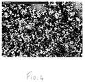
- the particles have a low bulk density, in the range 0.2-0.5 g/cm 3 , and a substantially irregular, i.e. not spherical, shape such for example shown in the photo of Fig. 4 (by scanning electronic microscope (SEM)).
- SEM scanning electronic microscope
- the coagulum particles have therefore few industrial applications. For example in applications as the powder coating, an average particle size in the range 25-80 ⁇ m is required. This means that only one portion of the coagulum is obtainable by sieving. However, the sieving of particles having a so small size is difficult since clogging of the sieves takes place. On the other hand by using the coagulum as such, a non uniform coating is obtained having different properties.
- these coagulum particles cannot be used in rotomoulding and rotolining applications. Indeed, for these applications they must necessarily be extruded and supplied to the users under the form of milled or unmilled pellets, having sizes from 100 ⁇ m to 1,000 ⁇ m.
- milled or unmilled pellets having sizes from 100 ⁇ m to 1,000 ⁇ m.
- the coagulum particles flow with difficulty during the extrusion process. This poor flowability often implies these two drawbacks: 1) a low extruder productivity and 2) block in some extruder section, with consequent bad functioning of the extruder.
- PTFE as inert support under the form of particles having an average size in the range 200-500 ⁇ m
- This porous PTFE support is mainly formed by particles with an irregular, not spherical, shape, having a low bulk density, in the range 0.3-0.5 g/cm 3 . Due to the low bulk density, it is necessary to carefully use this support, since it easily tends to compress itself and to become a compact solid rather than to remain porous, when it is sbjected to stress forces during the use and during the gas-chromatography column packing. For this reason, during the column packing phase, a cooling under 0°C is necessary to disperse the static load and harden this support.
- this inert support because of the non spherical shape of the particles, has an empty space degree which considerably changes with the loss of pressure, wherefore the columns result particularly sensible to any variation of the loss of pressure which can lead to a breaking of the support continuity.
- the obtained packing having a low bulk density, shows furthermore unsatisfactory mechanical and electric properties negatively affecting the column efficiency.
- the coagulum particles deriving from the conventional coagulation techniques having a very low bulk density, show the drawback to easily disperse in the working environment due to their extreme lightness with consequent loss of useful product in the application phase and problems of environmental pollution for the operators.
- Another drawback resides in that they show an irregular or "dendritic" structure, which implies a low flowing capability and therefore transfer difficulty for clogging problems. This poor flowing capability limits the effectiveness of their use in all the applications where free-flowing properties are required, for example for the above applications.
- An object of the present invention are therefore TFE thermoprocessable copolymer microspheres having a substantially spherical shape for at least 95% by weight, the average size of the microspheres being in the range 25 ⁇ m-2 mm, the bulk density being in the range 0.5-1.1 g/cm 3 , preferably 0.55-1.0 g/cm 3 .
- thermoprocessable copolymers polymers obtained by TFE polymerization with one or more monomers containing at least one ethylene type unsaturation are meant.
- hydrogenated olefins preferably in addition to the above mentioned comonomers can be mentioned.
- hydrogenated olefins are ethylene, propylene, butene and isobutene.
- the comonomer amount in the copolymer is between about 0.05 and 18% by weight, preferably 0.5 and 10% by weight, and it depends on the type of comonomer.
- the TFE copolymers can also be amorphous-vitrous depending on the comonomer. They can be obtained for example by using as comonomers the dioxoles or the monomers which cyclize during the polymerization. In this case the comonomer amount can be much higher, generally higher than 20% by weight.
- the TFE copolymers of the present invention can be semicrystalline and amorphous-vitrous, provided they are thermoprocessable.
- the skilled is easily capable to determine, by routine tests, the comonomer amount to have a thermoprocessable polymer, i.e. thermomouldable.
- thermoprocessable copolymers examples include:
- thermoprocessable copolymers preferred in the present invention are:
- thermoprocessable copolymers of the invention can be carried out in emulsion according to methods known in the prior art, preferably according to the processes described in USP 5,498,682 and USP 5,463,006. Polymerization latexes are obtained from which the microspheres of the invention are obtained by the process reported hereunder.
- microspheres of the invention are obtained in an equipment formed by a coagulation apparatus having a cylindrical shape shown in Figure 1, where the reference numbers show:
- the ratio between height and internal diameter is in the range 1-3.
- a series of stirrers assembled along the axis of the cylindrical body are included. Stirrers can have a type of axial, radial or mixed movement, but the radial movement is preferred.
- the number of stirrers can range from 1 to 4, depending on the ratio between the height of the coagulation apparatus and its internal diameter. When multiple stirrers are used, a combination of different movements can be applied.
- the stirrer diameter can range between 0.3 and 0.7 with respect to the internal diameter of the cylindrical body. It is preferred to have a series of baffles in the coagulation apparatus and in this case a meaningful clearance between the baffles and the coagulation apparatus wall must be left.
- the shape of the coagulation apparatus bottom can be arbitrary, but a conic shape is preferred since it allows to easily discharge the material from the coagulation apparatus after coagulation.
- a filter (5) is provided in the upper part of the coagulation apparatus so that the fluoropolymer microspheres are kept inside the coagulation apparatus and do not come out together with the water during functioning of the coagulation apparatus.
- Above the filter a vertical pipe is installed, where the liquid height can gradually regulate the pressure in the coagulation apparatus during the coagulation.
- pressure regulation method can be replaced by pressure control devices.
- the height of the vertical pipe h is between 0 and 5 meters.
- Another object of the present invention is a process for obtaining the TFE copolymer microspheres of the present invention. Such process is essential for obtaining the shape and bulk density features of the invention. Said process includes the use of the above described coagulation apparatus in semi-continuous conditions.
- the coagulation apparatus is free from air, filled with water and a coagulant.
- coagulants acids, bases and salts, for example nitric acid, NaOH, etc.
- All the coagulants known for the coagulation of the TFE copolymer latexes can be used.
- the coagulant is an acid or a base it is used at a concentration between 0 and 0.5 moles/litre.
- the coagulant is a salt, the coagulant concentration can even be higher.
- the temperature at which coagulation is carried out is in the range 5°-90°C, preferably 15°-70°C.
- the pressure is determined by the height of the above defined vertical pipe of the coagulation apparatus.
- the mixing rate can range between 5 and 25 rps, preferably 10 and 20 rps.
- the latex coming from the polymerization of the TFE copolymer is continuously fed to the semi-continuous stirred coagulation apparatus.
- a coagulant is fed continuously separately.
- Water is taken in a continuous way from the upper part of the coagulation apparatus, where a filter is placed so that the fluoropolymer microspheres do not come out together with the water and they are therefore kept inside the reactor so as to form microspheres having the desired size.
- the latex and the coagulant are fed at least in two steps, preferably in three steps.
- the polymer concentration of the latex ranges from 25 g/litre to 300 g/litre, preferably 50-200 g/litre; the latex feeding flow-rate is in the range 5 1/hour-45 1/hour.
- the time of this first step is lower than 10 minutes.
- the second step is optional and consists in ending the nucleation, for example without any polymer feeding for some minutes, or feeding only water, or water containing a limited amount of polymer, for example a polymer flow-rate (product between latex flow-rate and polymer concentration in the latex) corresponding to 10% of that fed in the first step.
- a polymer flow-rate product between latex flow-rate and polymer concentration in the latex
- the third step (growing step) considers a polymer concentration of the fed latex between 25 g/litre and up to 300 g/litre, preferably between 50 and 200 g/litre; the latex feeding flow-rate is in the range 5 1/hour-30 1/hour.
- the time of this-third step is higher than 15 minutes.
- the fluoropolymer microspheres are discharged in a discontinuous way from the bottom of the coagulation apparatus having the size and bulk density of the present invention. Subsequently the microspheres are subjected to a drying step at a temperature in the range 170°-280°C.
- the microspheres of the TFE copolymers of the invention can be used in powder coating applications, wherein dried powders of fluoropolymer are sprayed by an electrostatic gun on a metal article in order to supply anticorrosion coatings to the various equipments used in the chemical industry.
- the microspheres can besides be used in rotomoulding and rotolining applications.
- the rotomoulding is a rotational moulding technique wherein the fluoropolymer is introduced in a mould having a suitable shape which is heated at high temperatures and maintained under rotation until a fluoropolymer manufactured article having the mould shape is obtained.
- Manufactured articles typically obtainable by rotomoulding are tanks, bottles, vessels for silicon wafers.
- a metal substratum has to be coated by rotational moulding with a protective fluoropolymer layer
- the fluoropolymer is directly fed inside the metal substratum which is heated and maintained under rotation until obtaining a fluoropolymer layer having the desired thickness.
- This technique is called rotolining and is used for coating pipes, fitting, valves and tanks.
- microspheres Another application of the microspheres is the flame spraying technique. It essentially consists in the flowing of the fluoropolymer to be applied as coating through a flame generated by a gas combustion. The fluoropolymer, passing through the flame undergoes a quick heating, so reaches the substratum to be coated in a melting state. By this technique it is possible to apply fluoropolymer coatings to ceramic and metal substrata. Furthermore, when the microspheres pass through a flame, the low molecular weight organic substances, such for example surfactants, emulsifiers, etc. evaporate and burn at the flame temperature. Therefore fluoropolymer microspheres are purified by using the flame spraying technique thus giving coatings containing a small amount of contaminants.
- the flame spraying technique essentially consists in the flowing of the fluoropolymer to be applied as coating through a flame generated by a gas combustion. The fluoropolymer, passing through the flame undergoes a quick heating, so reaches the substra
- the flame spraying technique is a technique which avoids the use of solvents and therefore is particularly desired to have coatings with not polluting processes.
- gases for the flame hydrogen, acetylene, methane, etc., preferably hydrogen, are used.
- microspheres having a narrow distribution of particle diameters, it is possible to carry out the flame spraying in an optimal way.
- the fluoropolymer microspheres of the invention show the advantage that when they come into contact with the flame they melt, but they do not decompose during the residence time of the polymer in contact with the flame. The residence times must be such as to make the polymer to melt to give the coating, but not to cause its decomposition.
- the fluoropolymer microspheres, having a narrow size distribution allow to achieve these results.
- the fluoropolymer microspheres have free-flowing properties and therefore they are suitable in an optimal way to the use in said applications overcoming the mentioned drawbacks of the prior art.
- the microspheres As regards the application as inert support in gas-chromatography columns, the microspheres, having a regular morphology and high bulk density, form a polymer packing the empty space degree of which is scarcely depending on the variations of the pressure losses or on cyclic variations of the temperature. Besides, the microspheres of the invention show a higher mechanical resistance and a reduced electrostatic effect with respect to the PTFE particles used in the prior art. At last the packing formed by the microspheres of the invention shows properties of higher stability and assures a high separation efficiency of the components in the gas-chromatography column, as shown in the
- the fluoropolymer microspheres can besides advantageously be used as support for stationary phases to be used in chromatographic separation processes in gaseous or liquid phase carried out in a discontinuous (e.g. preparative columns) or in a continuous way (e.g. annular or simulated mobile bed chromatography).
- a semi-batch coagulation apparatus is used, formed by a reactor having an internal diameter of 200 mm and height of 500 mm, equipped with 3 stirrers of the Rushton turbine type. From the upper part of the coagulation apparatus the water is continuously taken away and a filter (200 mesh) is placed to keep the fluoropolymer particles inside the coagulation apparatus.
- a vertical section of the used semi-batch coagulation apparatus is shown in Figure 1.
- the latex of a TFE/PPVE (perfluoropropylvinylether) thermoprocessable copolymer called PFA has been prepared according to Example 1 of USP 5,463,006, but by introducing PPVE in the reactor and feeding a gaseous TFE mixture, without using perfluoromethylvinylether.
- the introduced PPVE amount is such as to have 1.8% by moles of PPVE in the final copolymer.
- the so obtained latex is fed into said coagulation apparatus free from air and initially filled with an aqueous solution of HNO 3 (coagulant) at a concentration 0.0631 moles/litre.
- the operating conditions are a mixing rate equal to 15 rev/sec and a coagulation temperature equal to 55°C.
- the latex and, as coagulant, a HNO 3 solution having a concentration 0.5 moles/litre are separately and continuously fed to the coagulation apparatus.
- the feeding procedure of the latex and of the coagulant follows three steps.
- the first step is characterized by the following parameters:
- the latex of a copolymer formed by a TFE thermoprocessable -polymer containing 0.9% by weight of PPVE and 6.4% by weight of PMVE, called MFA and obtained by polymerization according to Example 2 of USP 5,463,006 is fed to the coagulation apparatus described in Example 1, free from air and initially filled with an aqueous solution of HNO 3 at a concentration 0.1 moles/litre.
- a mixing rate equal to 18 rev/sec and a coagulation temperature equal to 60°C are selected as operating conditions.
- the polymer latex and as coagulant a HNO 3 solution having a concentration 0.5 moles/litre are separately and continuously fed to the coagulation apparatus.
- the feeding procedure of the latex and o the coagulant follows three steps.
- the first step is characterized by the following parameters:
- the latex of the TFE/PPVE/PMVE copolymer used in Example 2 is fed to the coagulation apparatus described in Example 1, free from air and initially filled with an aqueous solution of HNO 3 at a concentration 0.1 moles/litre.
- a mixing rate equal to 18 rev/sec and a coagulation temperature equal to 35°C are selected as operating conditions.
- the polymer latex and as coagulant a HNO 3 solution having a concentration 3.54 moles/litre are separately and continuously fed to the coagulation apparatus.
- the feeding procedure of the latex and of the coagulant follows three steps.
- the first step is characterized by the following parameters:
- a batch coagulation apparatus of conventional type formed by a reactor having an internal diameter of 200 mm and a height of 500 mm, equipped with 2 stirrers of the Rushton turbine type, is used.
- a HNO 3 solution is added until a pH equal to 1 is reached.
- the mixing rate is increased up to 12 rev/sec until a complete particle coagulation.
- the properties of the obtained coagulum particles, after drying at 265°C are the following:
- a batch coagulation apparatus of conventional type formed by a reactor having an internal diameter of 200 mm and a height of 500 mm, equipped with 2 stirrers of the Rushton turbine type, is used.
- a HNO 3 solution is added until a pH equal to 1 is reached.
- the mixing rate is increased up to 11 rev/sec until a complete particle coagulation.
- the properties of the obtained coagulum particles, after drying at 265°C are the following:
- the fluoropolymer microspheres of the invention are used for moulding a manufactured article by rotational moulding.
- the macroscopic parameters which determine the quality of a molded article by rotational moulding are:
- Microspheres of a copolymer having the composition indicated in Example 2 and having the bulk density and the granulometric distribution defined in Example 2, have been used to mould an article having a hollow cylinder shape.
- the mould is formed by a carbon steel hollow cylinder having an internal diameter of 140 mm, a length of 180 mm, a thickness of 3 mm.
- microspheres obtained in Example 2 in an amount equal to 300 g are introduced in the mould through a hole having a 1 cm diameter, placed on one side of the cylinder and having also a venting function for the mould.
- the mould is then introduced in the hot oven and let rotate around a single axis at a rotation rate of 5 rpm. During the rotation, the oven temperature is initially maintained at 290°C for 15 minutes and subsequently at 340°C for 70 minutes.
- a moulded article is obtained having the following properties:
- the good free-flowing properties of the fluoropolymer microspheres of the invention and their spherical morphology allow to obtain a final article of a very good quality.
- Microspheres of a copolymer having the composition indicated in Example 1 and having the bulk density and granulometric distribution defined in Example 1, have been used to mould an article having a hollow cylinder shape.
- the mould is formed by a carbon steel hollow cylinder having an internal diameter of 140 mm, a length of 180 mm, a thickness of 3 mm.
- microspheres obtained in Example 1 in an amount equal to 300 g are introduced in the mould through a hole having a 1 cm diameter, placed on one side of the cylinder and having also a venting function for the mould.
- the mould is then introduced in the hot oven and let rotate around a single axis at a rotation rate of 5 rpm. During the rotation, the oven temperature is initially maintained at 310°C for 15 minutes and subsequently at 360°C for 70 minutes.
- a moulded article is obtained having the following properties:
- the good free-flowing properties of the fluoropolymer microspheres of the invention and their spherical morphology allow to obtain a final article of a very good quality.
- Example 5 The coagulum particles obtained in Example 5 having the morphological and granulometric properties indicated in Example 5, are used to mould an article by rotomolding.
- the poor free-flowing properties of the used fluoropolymer particles and their irregular morphology determine the obtainment of an unusable moulded article for the presence of various defects.
- Example 8 has been repeated, but using the coagulum particles obtained in Example 4 with the morphological and granulometric properties indicated in Example 4. The final article obtained shows the same features shown in Example 8.
- the fluoropolymer microspheres of the invention obtained in Example 3, are used in a powder coating application.
- the obtained thicknesses of the fluoropolymer coating range from 140 to 200 microns.
- RESULTS on both plates having a thickness of 3 and 8 mm, both at the 10 kV and 30 kV voltage a smooth coating and free from bubbles is obtained.
- the coagulum particles obtained in Example 5 are used in a powder coating application.
- the obtained thicknesses of the fluoropolymer coating range from 100 to 280 microns. RESULTS: it is noticed that on the plate having a thickness both of 3 and 8 mm, at a 30 kV voltage a not uniform coating and free from bubbles is obtained.
- microspheres of a copolymer described in Example 2 and having the bulk density and granulometric distribution defined in Example 2 are used as inert support in a chromatographic column to separate a gaseous mixture formed of F 2 and CF 3 CF 2 CF 2 OF. By sieving, the microspheres having sizes in the range 250-400 ⁇ m are separated for the use in this application.
- the used column indicated with (B), has a length of 3 meters, an internal diameter of 4 mm and uses KEL F® (polychlorotrifluoroethylene) as stationary phase.
- the separation temperature at which column (B) operates is of 50°C.
- the graph of Figure 2 referred to the column (B) shows that, by using as inert support the fluoropolymer microspheres of the invention, a very good separation of F 2 from CF 3 CF 2 CF 2 OF is obtained, as it can be deduced from the time distance of the two peaks and from their symmetry.
- PTFE particles commercially called Chromosorb T® having the bulk density, effective density and granulometric distribution indicated in Table 1, are used as inert support in a chromatographic column to separate the same gaseous mixture F 2 /CF 3 CF 2 CF 2 OF of Example 10.
- the used column indicated with (A), has a length of 7 meters, an internal diameter of 4 mm and uses KEL F® (polychlorotrifluoroethylene) as stationary phase.
- Example 10 shows that by using as inert support Chromosorb T® , although the column has a length more than double with respect to the column (B), there is a lower separation of the two components the mixture, as it can be deduced from the greater distance of the two peaks and from their poor symmetry.
- Example 10 Example 11 (Comp.) Support type MFA microspheres Chromosorb T Support shape Spherical Dendritic Support size ( ⁇ m) 250-400 250-420 Bulk density (g/ml) 0.82 0.42 Specific density (g/ml) 2.15 2.39 Surface area BET (m 2 /g) 10 7
- the fluoropolymer microspheres of the invention are used in a flame spraying application.
- Microspheres of a thermoprocessable amorphous copolymer TFE/TTD (2,2,4-trifluoro-5-trifluoro-methoxy-1,3-dioxole) are used.
- the molar ratio between TFE and TTD is equal to 60/40.
- Said copolymers are described in USP 5,498,682.
- the fluoropolymer microspheres of the invention are fed starting from a glass container. They have an average diameter equal to 100 ⁇ , the feeding flow-rate of the microspheres is equal to 0.5 g/min.
- the flame spraying is carried out by a UTP Mini-Spray-Jet® gun.
- the flame is generated by feeding an oxygen and acetylene mixture.
- the oxygen flow drags the fluoropolymer microspheres through the flame.
- the desired temperature in the flame can be obtained by regulating the flow and the molar ratio between oxygen and acetylene.
- a fluoropolymer film having a thickness of about 200 ⁇ m is deposited on the aluminum plate.
Landscapes
- Chemical & Material Sciences (AREA)
- Health & Medical Sciences (AREA)
- Chemical Kinetics & Catalysis (AREA)
- Medicinal Chemistry (AREA)
- Polymers & Plastics (AREA)
- Organic Chemistry (AREA)
- Dispersion Chemistry (AREA)
- Processes Of Treating Macromolecular Substances (AREA)
- Addition Polymer Or Copolymer, Post-Treatments, Or Chemical Modifications (AREA)
Abstract
Description
- C3-C8 perfluorolefins, such as hexafluoropropene (HFP);
- C2-C8 hydrogenated fluoroolefins, such as vinyl fluoride
(VF), vinylidene fluoride (VDF), trifluoroethylene,
hexafluoroisobutene, perfluoroalkylethylene CH2=CH-Rf,
wherein Rf is a C1-C6 perfluoroalkyl; - C2-C8 chloro- and/or bromo- and/or iodo-fluoroolefins, such as chlorotrifluoroethylene (CTFE);
- CF2=CFORf (per)fluoroalkylvinylethers (PAVE), wherein Rf is a C1-C6 (per)fluoroalkyl, for example CF3, C2F5, C3F7;
- CF2=CFOX (per)fluoro-oxyalkylvinylethers, wherein X is: a C1-C12 alkyl, or a C1-C12 oxyalkyl, or a C1-C12 (per)fluoro-oxyalkyl having one or more ether groups, for example perfluoro-2-propoxy-propyl;
- fluorodioxoles, preferably perfluorodioxoles;
- non conjugated dienes of the type:
- CF2=CFOCF2CF2CF=CF2,
- CFX1=CX2OCX3X4OCX2=CX1F
- FEP copolymers, i.e. tetrafluoroethylene-hexafluoropropene (TFE/HFP) copolymers, described for example in USP 2,946,763;
- FEP copolymers modified with a third monomer, for example TFE/HFP/PEVE (perfluoroethylvinylether) copolymers described in EP 759,446 and USP 5,677,404;
- TFE/HFP/PMVE (perfluoromethylvinylether) copolymers described in USP 5,688,885;
- TFE/HFP/PPVE (perfluoropropylvinylether) copolymers described
in USP 4,029,868.
In the FEP copolymers the HFP amount is about 5-10% by moles, while the perfluoroalkylvinylether amount in FEPs modified with vinylether is between about 0.2 and 3% by weight.
- TFE/PPVE copolymers commecially called PFA, described in USP 3,635,926;
- copolymers TFE/PMVE/fluorinated monomer selected from the above mentioned ones, preferably PPVE, wherein the PMVE amount ranges from 0.5 to 13% by weight, the fluorinated monomer amount ranges from 0.5 to 3% by weight. See for example USP 5,463,006; the terpolymer TFE/PMVE/PPVE is commercially called MFA.
- copolymers TFE/PMVE/fluorinated dioxole wherein PMVE is in the range 0.5%-13% by weight, the fluorinated dioxole is in the range 0.05%-3% by weight. Such copolymers are described in USP 5,498,682. As fluorinated dioxole, 2,2,4-trifluoro-5-trifluoro-methoxy-1,3- dioxole (TTD) is preferably used.
The first step is characterized by the following parameters:
- Feeding flow-rate of latex: 12 litres/hour
- Polymer concentration in the latex: 100 g/litre
- Feeding flow-rate of HNO3 solution: 1.73 litres/hour
- Length of time: 7 minutes
- Feeding flow-rate of latex: 6.4 litres/hour
- Polymer concentration in the latex: 50 g/litre
- Feeding flow-rate of HNO3 solution: 0.92 litres/hour
- Length of time: 13 minutes. The third step is characterized by the following parameters:
- Feeding flow-rate of latex: 10 litres/hour
- Polymer concentration in the latex: 100 g/litre
- Feeding flow-rate of HNO3 solution: 1.44 litres/hour
- Length of time: 75 minutes.
- Morphology: spherical
- Bulk density: 0.818 g/cm3
- Specific surface B.E.T.: 8 m2/g
- Average microsphere diameter: 230 µm
- Granulometric distribution of the microspheres:
Fraction by weight (%) 0.7 4.0 95.3 Size (µm) 45-90 90-180 180-300
The first step is characterized by the following parameters:
- Feeding flow-rate of latex: 12 litres/hour
- Polymer concentration in the latex: 150 g/litre
- Feeding flow-rate of HNO3 solution: 3 litres/hour
- Length of time: 10 minutes
- Feeding flow-rate of latex: 6 litres/hour
- Polymer concentration in the latex: 0.0 g/litre
- Feeding flow-rate of HNO3 solution: 1.5 litres/hour
- Length of time: 10 minutes.
- Feeding flow-rate of latex: 10 litres/hour
- Polymer concentration in the latex: 150 g/litre
- Feeding flow-rate of HNO3 solution: 2.5 litres/hour
- Length of time: 120 minutes.
- Morphology: spherical
- Bulk density: 0.82 g/cm3
- Specific surface B.E.T.: 10 m2/g
- Average microsphere diameter: 250 µm
- Granulometric distribution of the microspheres:
Fraction by weight (%) 1.7 6.3 42.3 49.7 Size (µm) 45-106 106-180 180-300 300-400
The first step is characterized by the following parameters:
- Feeding flow-rate of latex: 40 litres/hour
- Polymer concentration in the latex: 150 g/litre
- Feeding flow-rate of HNO3 solution: 1.16 litres/hour
- Length of time: 5 minutes
- Feeding flow-rate of latex: 6.4 litres/hour
- Polymer concentration in the latex: 0.0 g/litre
- Feeding flow-rate of HNO3 solution: 0.19 litres/hour
- Length of time: 15 minutes.
- Feeding flow-rate of latex: 20 litres/hour
- Polymer concentration in the latex: 150 g/litre
- Feeding flow-rate of HNO3 solution: 0.58 litres/hour
- Length of time: 18 minutes.
- Morphology: spherical
- Bulk density: 0.692 g/cm3
- Average microsphere diameter: 62 µm
- Granulometric distribution of the microspheres:
Fraction by wt. (%) 4.5 93.1 2.4 Size (µm) 0-32 32-106 106-180
- Morphology: non spherical
- Bulk density: 0.45 g/cm3
- Average particle diameter: 30 µm
- Granulometric distribution of the particles:
Fraction by wt. (%) 62.8 23.2 14.0 Size (µm) 0-32 32-45 45-90
- Morphology: non spherical
- Bulk density: 0.49 g/cm3
- Average particle diameter: 30 µm
- Granulometric distribution of the particles:
Fraction by wt. (%) 61.4 26.6 12.0 Size (µm) 0-32 32-45 45-90
- absence of bubbles
- absence of clots or agglomerates
- smooth surface
- FINAL ARTICLE THICKNESS:
- not determinable due to the surface irregularity
- FINAL ARTICLE QUALITY:
- full of bubbles and clots
- the plates have been pre-heated in an oven at 380°C;
- the microspheres are hot applied on the plate for an application time of about 40 seconds;
- after spraying the plate has been put again in the oven at 380°C and left in the oven for 30 minutes.
- powder flow-rate respectively of 400 and 150 g/min;
- voltage, respectively of 10 and 30 kV;
RESULTS: on both plates having a thickness of 3 and 8 mm, both at the 10 kV and 30 kV voltage a smooth coating and free from bubbles is obtained.
- the plates have been pre-heated in an oven at 380°C;
- the particles are hot applied on the plate for an application time of about 40 seconds;
- after spraying the plate has been put again in the oven at 380°C and left in the oven for 30 minutes.
- powder flow-rate respectively of 400 and 150 g/min;
- voltage, respectively of 10 and 30 kV;
RESULTS: it is noticed that on the plate having a thickness both of 3 and 8 mm, at a 30 kV voltage a not uniform coating and free from bubbles is obtained.
| Example 10 | Example 11 (Comp.) | |
| Support type | MFA microspheres | Chromosorb T |
| Support shape | Spherical | Dendritic |
| Support size (µm) | 250-400 | 250-420 |
| Bulk density (g/ml) | 0.82 | 0.42 |
| Specific density (g/ml) | 2.15 | 2.39 |
| Surface area BET (m2/g) | 10 | 7 |
- pressure of oxygen feeding line = 3.5 absolute bar;
- pressure of C2H2 feeding line = 1.5 absolute bar;
- along the flame axis the temperature decreases from 1400°C to 900°C;
- in the zone comprised between the flame end and the aluminum plate the temperature is equal to 600°C.
| Before the flame spraying | After the flame spraying | |
| Mw (g/mole) | 895,000 | 326,000 |
| η (cm3/g) | 43 | 30 |
| Residual surfactant (ppm) | 1600 | 20 |
Claims (19)
- Tetrafluoroethylene (TFE) thermoprocessable copolymer microspheres having a substantially spherical shape for at- least 95% by weight, the average size of the microspheres being in the range 25 µm-2 mm, the bulk density being in the range 0.5-1.1 g/cm3, preferably 0.55-1.0 g/cm3.
- Microspheres according to claim 1, wherein in the TFE thermoprocessable copolymers the comonomers are selected from:C3-C8 perfluorolefins, such as hexafluoropropene (HFP);C2-C8 hydrogenated fluoroolefins, such as vinyl fluoride (VF), vinylidene fluoride (VDF), trifluoroethylene, hexafluoroisobutene, perfluoroalkylethylene CH2=CH-Rf, wherein Rf is a C1-C6 perfluoroalkyl;C2-C8 chloro- and/or bromo- and/or iodo-fluoroolefins, such as chlorotrifluoroethylene (CTFE);CF2=CFORf (per)fluoroalkylvinylethers (PAVE), wherein Rf is a C1-C6 (per)fluoroalkyl, for example CF3, C2F5, C3F7;CF2=CFOX (per)fluoro-oxyalkylvinylethers, wherein X is: a C1- C12 alkyl, or a C1 - C12 oxyalkyl, or a C1 - C12 (per)fluoro-oxsyalkyl having one or more ether groups;fluorodioxoles, preferably perfluorodioxoles;non conjugated dienes of the type:CF2=CFOCF2CF2CF=CF2,CFX1 =CX2OCX3X4OCX2=CX1F
wherein X1 and X2, equal to or different from each other, are F, Cl or H; X3 and X4, equal to or different from each other, are F or CF3, which during the polymerization cyclopolymerize;hydrogenated olefins, preferably in addition to the above mentioned comonomers. - Microspheres according to claims 1-2, wherein the TFE thermoprocessable copolymers are both semicrystalline and amorphous-vitrous.
- Microspheres according to claims 1-3, wherein in the semicrystalline thermoprocessable copolymers the comonomer amount is between about 0.05 and 18% by weight, preferably 0.5 and 10% by weight.
- Microspheres according to claims 1-4, whereien the thermoprocessable copolymers are selected from:FEP copolymers, i.e. tetrafluoroethylene-hexafluoropropene (TFE/HFP) copolymers;FEP copolymers modified with a third monomer, for example TFE/HFP/PEVE (perfluoroethylvinylether) copolymers;TFE/HFP/PMVE (perfluoromethylvinylether) copolymers;TFE/HFP/PPVE (perfluoropropylvinylether) copolymers.
- Microspheres according to claim 5, wherein the HFP amount is about 5-10% by moles, while the perfluoroalkylvinylether amount is between about 0.2 and 3% by weight.
- Microspheres according to claims 1-4, wherein the thermoprocessable copolymers are selected from:TFE/PPVE copolymers;copolymers TFE/PMVE/fluorinated monomer, preferably PPVE, wherein the PMVE amount ranges from 0.5 to 13% by weight, the fluorinated monomer amount ranges from 0.5 to 3% by weight.copolymers TFE/PMVE/fluorinated dioxole wherein PMVE is in the range 0.5%-13% by weight, the fluorinated dioxole is in the range 0.05%-3% by weight.
- Microspheres according to claim 7, wherein the fluorinated dioxole is 2,2,4-trifluoro-5-trifluoro-methoxy-1,3-dioxole (TTD).
- Equipment formed by the coagulation apparatus having a cylindrical shape of Figure 1, where the reference numbers show:(1) Jacket for maintaining the temperature in the coagulation apparatus at a desired value;(2) Outlet of the coagulated product;(3) Coagulant inlet;(4) Latex inlet;(5) Filter;(6) Liquid outlet.
- A process for obtaining the microspheres according to claims 1-8, wherein the equipment of claim 9 is used.
- A process according to claim 10, wherein in the initial conditions the coagulation apparatus is free from air, filled with water and a coagulant selected from acids, bases and salts.
- A process according to claims 9-11, wherein when the steady state is reached, the polymerization latex is continuously fed to the semi-continuous coagulation apparatus; separately a coagulant is fed continuously, while the water is taken in a continuous way from the upper part of the coagulation apparatus by a filter.
- A process according to claims 9-12, wherein the temperature is in the range 5°-90°C, preferably 15°-70°C; the mixing rate ranges between 5 and 25 rps, preferably 10 and 20 rps.
- A process according to claims 9-13, wherein the latex and the coagulant are fed at least in two steps, preferably in three steps.
- A process according to claim 14, wherein:in the first step the polymer concentration of the latex ranges from 25 g/litre to 300 g/litre, preferably 50-200 g/litre; the latex feeding flow-rate is in the range 5 1/hour-45 1/hour; the time of this step is lower than 10 minutes;the second step is optional and consists in ending the nucleation, preferably by feeding a polymer flow-rate corresponding to 10% of that fed in the first step;in the third step the polymer concentration of the fed latex is between 25 g/litre and 300 g/litre, preferably between 50 and 200 g/litre; the latex feeding flow-rate is in the range 5 1/hour-30 1/hour; the time of this step is higher than 15 minutes.
- A process according to claims 9-15, wherein after a total residence time comprised between about 25 minutes and 10 hours, the fluoropolymer microspheres are discharged in a discontinuous way from the bottom of the coagulation apparatus; subsequently the microspheres are subjected to a drying step at a temperature in the range 170°-280°C.
- Use of the microspheres according to claims 1-8 in powder coating and flame spraying applications.
- Use of the microspheres according to claims 1-8 in rotomoulding and rotolining applications.
- Use of the microspheres according to claims 1-8 as inert support in chromatographic separation columns in gaseous or liquid phase.
Applications Claiming Priority (2)
| Application Number | Priority Date | Filing Date | Title |
|---|---|---|---|
| ITMI001418 | 2000-06-23 | ||
| IT2000MI001418A IT1318595B1 (en) | 2000-06-23 | 2000-06-23 | THERMOPROCESSABLE TETRAFLUOROETHYLENE COPOLYMER MICROSPHERES. |
Publications (4)
| Publication Number | Publication Date |
|---|---|
| EP1172380A2 true EP1172380A2 (en) | 2002-01-16 |
| EP1172380A3 EP1172380A3 (en) | 2004-03-31 |
| EP1172380B1 EP1172380B1 (en) | 2008-10-15 |
| EP1172380B2 EP1172380B2 (en) | 2012-10-24 |
Family
ID=11445329
Family Applications (1)
| Application Number | Title | Priority Date | Filing Date |
|---|---|---|---|
| EP01114605A Expired - Lifetime EP1172380B2 (en) | 2000-06-23 | 2001-06-19 | Thermoprocessable tetrafluoroethylene copolymer microspheres |
Country Status (6)
| Country | Link |
|---|---|
| US (2) | US6624269B2 (en) |
| EP (1) | EP1172380B2 (en) |
| JP (1) | JP2002060432A (en) |
| DE (1) | DE60136133D1 (en) |
| IT (1) | IT1318595B1 (en) |
| RU (1) | RU2271366C2 (en) |
Cited By (2)
| Publication number | Priority date | Publication date | Assignee | Title |
|---|---|---|---|---|
| EP1621559A3 (en) * | 2004-07-30 | 2006-06-07 | Solvay Solexis S.p.A. | TFE-based thermoprocessable copolymers |
| US20120226077A1 (en) * | 2004-07-30 | 2012-09-06 | Solvay S.A. | Fluoroelastomers |
Families Citing this family (14)
| Publication number | Priority date | Publication date | Assignee | Title |
|---|---|---|---|---|
| US8013089B2 (en) * | 2002-12-06 | 2011-09-06 | E. I. Du Pont De Nemours And Company | Fluoropolymer composition for lining adhesion to a surface |
| US7892600B2 (en) | 2002-12-06 | 2011-02-22 | E. I. Du Pont De Nemours And Company | Rotolining process |
| US7179941B2 (en) * | 2003-01-23 | 2007-02-20 | Sanofi-Aventis Deutschland Gmbh | Carbonylamino-substituted acyl phenyl urea derivatives, process for their preparation and their use |
| DE502005008866D1 (en) * | 2005-04-09 | 2010-03-04 | Vestolit Gmbh & Co Kg | Process for the continuous agglomeration of PVC dispersions |
| DE602007003750D1 (en) * | 2006-10-03 | 2010-01-21 | 3M Innovative Properties Co | MULTILAYER ARTICLES AND METHOD FOR INCREASING THEIR DUTY LIFE |
| US20090110833A1 (en) * | 2007-10-31 | 2009-04-30 | Gala Industries, Inc. | Method for abrasion-resistant non-stick surface treatments for pelletization and drying process equipment components |
| JP5344212B2 (en) * | 2008-03-24 | 2013-11-20 | 地方独立行政法人 岩手県工業技術センター | Forming method of resin film |
| RU2398789C1 (en) * | 2009-01-30 | 2010-09-10 | Общество с ограниченной ответственностью "Завод полимеров Кирово-Чепецкого химического комбината" (ООО "Завод полимеров КЧХК") | Method of producing granular heat-resistant copolymers of tetrafluoroethylene with ethylene and copolymers obtained using said method |
| JP5560239B2 (en) * | 2011-07-04 | 2014-07-23 | 信越化学工業株式会社 | Gas chromatography separation method for silane / chlorosilanes and column for gas chromatography |
| RU2528834C1 (en) * | 2013-05-15 | 2014-09-20 | Открытое акционерное общество "Нефтяная компания "Роснефть" | Polydicyclopentadiene microspheres and methods for production thereof |
| CN105319290A (en) * | 2014-08-04 | 2016-02-10 | 天津市长芦盐业总公司化工新材料工程技术中心 | Method for analyzing and measuring heptafluoropropyl trifluorovinyl ether |
| JP6977700B2 (en) * | 2018-11-14 | 2021-12-08 | 信越化学工業株式会社 | Molecular weight analysis method and separation / purification method for compounds by size exclusion chromatography |
| CN109776821B (en) * | 2018-12-18 | 2021-10-29 | 浙江巨化技术中心有限公司 | Modified PTFE dispersion resin and preparation method thereof |
| CN114230737B (en) | 2020-09-09 | 2023-08-01 | 中昊晨光化工研究院有限公司 | A kind of perfluoroether fluororubber and its preparation method and application |
Family Cites Families (32)
| Publication number | Priority date | Publication date | Assignee | Title |
|---|---|---|---|---|
| NL110421C (en) | 1957-03-29 | |||
| US3331822A (en) † | 1963-08-20 | 1967-07-18 | Thiokol Chemical Corp | Production of polytetrafluoroethylene molding powders by the aqueous suspension polymerization of tetrafluoroethylene with small amounts of perfluoroolefins containing from 3 to 4 carbon atoms |
| DE1542003A1 (en) * | 1966-01-15 | 1970-03-19 | Bosch Gmbh Robert | Process for the production of anodes for fuel cells |
| DE1745252B2 (en) * | 1966-05-25 | 1975-07-31 | E.I. Du Pont De Nemours And Co., Wilmington, Del. (V.St.A.) | Process for the production of a granular tetrafluoroethylene polymer |
| US3635926A (en) | 1969-10-27 | 1972-01-18 | Du Pont | Aqueous process for making improved tetrafluoroethylene / fluoroalkyl perfluorovinyl ether copolymers |
| US3864322A (en) * | 1973-04-12 | 1975-02-04 | Du Pont | Perfluorocarbon copolymer powders and preparation by spray drying |
| JPS5244576B2 (en) * | 1974-01-22 | 1977-11-09 | ||
| US4029868A (en) | 1976-03-10 | 1977-06-14 | E. I. Du Pont De Nemours And Company | Tetrafluoroethylene terpolymers |
| CA1145897A (en) * | 1979-07-19 | 1983-05-03 | Nur Gurak | Latex coagulation |
| CA1248292A (en) * | 1984-05-10 | 1989-01-03 | Marlin D. Buckmaster | Melt-processible tetrafluoroethylene copolymers and processes for preparing them |
| US4714756A (en) * | 1985-10-23 | 1987-12-22 | E. I. Du Pont De Nemours And Company | Process for preparing melt processible tetrafluoroethylene copolymer granules |
| US4675380A (en) † | 1985-10-25 | 1987-06-23 | E. I. Du Pont De Nemours And Company | Melt-processible tetrafluoroethylene/perfluoroolefin copolymer granules and processes for preparing them |
| JPH075743B2 (en) * | 1986-12-22 | 1995-01-25 | ダイキン工業株式会社 | Tetrafluoroethylene copolymer powder and method for producing the same |
| WO1989002905A1 (en) * | 1987-09-25 | 1989-04-06 | Mitsubishi Rayon Co., Ltd. | Process for continuously producing granular polymer and process for controlling particle size of said polymer |
| KR900700170A (en) * | 1988-03-24 | 1990-08-11 | 원본미기재 | Paralog Affinity Chromatography |
| IT1264125B1 (en) * | 1993-03-30 | 1996-09-16 | Ausimont Spa | FLUOROELASTOMERS WITH HIGH RESISTANCE TO POLAR SOLVENTS AND BASES |
| IT1264662B1 (en) | 1993-07-05 | 1996-10-04 | Ausimont Spa | PERFLURODIOSSOLS THEIR HOMOPOLYMERS AND COPOLYMERS AND THEIR USE FOR THE COATING OF ELECTRIC CABLES |
| IT1264661B1 (en) | 1993-07-05 | 1996-10-04 | Ausimont Spa | THERMOPROCESSABILIN COPOLYMERS OF TETRAFLUOROETHYLENE |
| RU2071479C1 (en) * | 1994-03-10 | 1997-01-10 | Акционерное общество "Пластполимер" | Process for preparing copolymers |
| IT1272863B (en) * | 1995-01-04 | 1997-07-01 | Ausimont Spa | THERMOPROCESSABLE COPOLYMERS OF TETRAFLUOROETHYLENE |
| JPH0952955A (en) * | 1995-08-11 | 1997-02-25 | Daikin Ind Ltd | Method for producing modified polytetrafluoroethylene granular powder |
| US5677404A (en) | 1996-02-23 | 1997-10-14 | E. I. Du Pont De Nemours And Company | Tetrafluoroethylene terpolymer |
| US5688885A (en) | 1995-08-17 | 1997-11-18 | E. I. Du Pont De Nemours And Company | Tetrafluoroethylene terpolymer |
| DE69601335T2 (en) | 1995-08-17 | 1999-08-12 | E.I. Du Pont De Nemours And Co., Wilmington, Del. | Tetrafluoroethylene terpolymer |
| CN1075086C (en) * | 1995-09-18 | 2001-11-21 | 大金工业株式会社 | Filler-containing polytetrafluoroethylene granular powder and manufacturing method thereof |
| JPH09178720A (en) * | 1995-12-27 | 1997-07-11 | Neos Co Ltd | Analysis of non-fluorine-based fat-soluble compounds |
| JP2000002697A (en) * | 1996-02-15 | 2000-01-07 | Nippon Futsuso Kogyo Kk | Liquid chromatography column and method for producing the same |
| FR2749310B1 (en) * | 1996-06-03 | 1998-08-14 | Atochem Elf Sa | PROCESS FOR PRODUCING COAGULATED POLYMER LATEX PARTICLES |
| JPH1087746A (en) * | 1996-09-11 | 1998-04-07 | Asahi Glass Co Ltd | Granulated tetrafluoroethylene copolymer and method for producing the same |
| JP3951277B2 (en) * | 1998-03-20 | 2007-08-01 | 旭硝子株式会社 | Ethylene / tetrafluoroethylene copolymer powder and molding method thereof |
| JP2000103865A (en) * | 1998-09-30 | 2000-04-11 | Asahi Glass Co Ltd | Method for producing fluoropolymer powder |
| JP4260965B2 (en) * | 1999-02-24 | 2009-04-30 | 三井・デュポンフロロケミカル株式会社 | Rotating lining method |
-
2000
- 2000-06-23 IT IT2000MI001418A patent/IT1318595B1/en active
-
2001
- 2001-06-19 EP EP01114605A patent/EP1172380B2/en not_active Expired - Lifetime
- 2001-06-19 DE DE60136133T patent/DE60136133D1/en not_active Expired - Lifetime
- 2001-06-21 JP JP2001188316A patent/JP2002060432A/en active Pending
- 2001-06-22 RU RU2001117585/04A patent/RU2271366C2/en not_active IP Right Cessation
- 2001-06-25 US US09/887,113 patent/US6624269B2/en not_active Expired - Lifetime
-
2003
- 2003-06-23 US US10/600,621 patent/US6809167B2/en not_active Expired - Lifetime
Cited By (4)
| Publication number | Priority date | Publication date | Assignee | Title |
|---|---|---|---|---|
| EP1621559A3 (en) * | 2004-07-30 | 2006-06-07 | Solvay Solexis S.p.A. | TFE-based thermoprocessable copolymers |
| US7544752B2 (en) | 2004-07-30 | 2009-06-09 | Solvay Solexis S.P.A. | TFE-based thermoprocessable copolymers |
| US20120226077A1 (en) * | 2004-07-30 | 2012-09-06 | Solvay S.A. | Fluoroelastomers |
| US8940944B2 (en) * | 2004-07-30 | 2015-01-27 | Solvay Solexis S.P.A. | Fluoroelastomers |
Also Published As
| Publication number | Publication date |
|---|---|
| EP1172380B2 (en) | 2012-10-24 |
| IT1318595B1 (en) | 2003-08-27 |
| DE60136133D1 (en) | 2008-11-27 |
| EP1172380A3 (en) | 2004-03-31 |
| US20040082746A1 (en) | 2004-04-29 |
| JP2002060432A (en) | 2002-02-26 |
| US6624269B2 (en) | 2003-09-23 |
| ITMI20001418A1 (en) | 2001-12-23 |
| EP1172380B1 (en) | 2008-10-15 |
| US6809167B2 (en) | 2004-10-26 |
| ITMI20001418A0 (en) | 2000-06-23 |
| US20020016427A1 (en) | 2002-02-07 |
| RU2271366C2 (en) | 2006-03-10 |
Similar Documents
| Publication | Publication Date | Title |
|---|---|---|
| US6809167B2 (en) | Tetrafluoroethylene thermoprocessable copolymer microspheres | |
| EP1171512B1 (en) | Sprayable powder of non-fibrillatable fluoropolymer | |
| EP1284850B1 (en) | Process for rotomolding with melt-extruded tfe/pave copolymer | |
| CN1079807C (en) | Process for producing granular powder of modified polytetrafluoroethylene | |
| JP2021006648A (en) | Fluoropolymer composition, molded article, and injection molded article | |
| CN102264806B (en) | Ethylene/tetrafluoroethylene copolymer granulation method | |
| CN107667144B (en) | Anti-stick treatment for low crystallinity fluoropolymer particles | |
| CN1293703A (en) | Multicomponent particles of fluoropolymer and high tmep. resistant non-dispersed polymer binder | |
| EP0226668A1 (en) | Process for treating melt-processible Tetrafluoroethylene/perfluoro(alkyl vinyl)- ether copolymers | |
| JPH10114846A (en) | Blend compositions of polymers with improved processability | |
| JP3718851B2 (en) | Filled polytetrafluoroethylene granular powder and process for producing the same | |
| CN1088463C (en) | Granulated powder of filled polytetra fluoroethylene for molding and production thereof | |
| RU2001117585A (en) | Microspheres of a thermoprocessable tetrafluoroethylene copolymer | |
| JP2002097330A (en) | Polytetrafluoroethylene composition, method for producing the same, and granulated product | |
| JP2015516025A (en) | Fluorinated polymer resin treatment using heating and oxygen source to reduce discoloration | |
| JPWO1997017392A1 (en) | Filler-containing polytetrafluoroethylene molding granulated powder and its manufacturing method | |
| JP4449111B2 (en) | Method for stabilizing fluorine-containing copolymer | |
| JPWO1997011111A1 (en) | Filler-containing polytetrafluoroethylene granular powder and its manufacturing method | |
| CN1196739A (en) | Filler-containing polytetrafluoroethylene granular powder and manufacturing method thereof | |
| EP1605011A1 (en) | Granulated powder of low-molecular polytetrafluoro- ethylene and powder of low-molecular polytetrafluoro- ethylene and processes for producing both | |
| CN1156517C (en) | Fluoropolymer Processing Methods | |
| JPH09505623A (en) | Low melting point tetrafluoroethylene copolymers and uses thereof | |
| JPH04185647A (en) | Production of granulated filled polytetrafluoroethylene powder | |
| JP2003026811A (en) | Fluorine composition as sealing material and method for producing the same |
Legal Events
| Date | Code | Title | Description |
|---|---|---|---|
| PUAI | Public reference made under article 153(3) epc to a published international application that has entered the european phase |
Free format text: ORIGINAL CODE: 0009012 |
|
| AK | Designated contracting states |
Kind code of ref document: A2 Designated state(s): AT BE CH CY DE DK ES FI FR GB GR IE IT LI LU MC NL PT SE TR |
|
| AX | Request for extension of the european patent |
Free format text: AL;LT;LV;MK;RO;SI |
|
| RAP1 | Party data changed (applicant data changed or rights of an application transferred) |
Owner name: AGORA' S.P.A. |
|
| RAP1 | Party data changed (applicant data changed or rights of an application transferred) |
Owner name: SOLVAY SOLEXIS S.P.A. |
|
| RIC1 | Information provided on ipc code assigned before grant |
Ipc: 7B 01J 20/26 B Ipc: 7C 08L 27/18 B Ipc: 7C 09D 5/03 B Ipc: 7C 08F 6/22 A Ipc: 7B 29C 41/00 B Ipc: 7B 01D 21/02 B Ipc: 7C 08J 3/16 B |
|
| PUAL | Search report despatched |
Free format text: ORIGINAL CODE: 0009013 |
|
| AK | Designated contracting states |
Kind code of ref document: A3 Designated state(s): AT BE CH CY DE DK ES FI FR GB GR IE IT LI LU MC NL PT SE TR |
|
| AX | Request for extension of the european patent |
Extension state: AL LT LV MK RO SI |
|
| 17P | Request for examination filed |
Effective date: 20040924 |
|
| AKX | Designation fees paid |
Designated state(s): DE FR GB IT |
|
| 17Q | First examination report despatched |
Effective date: 20051006 |
|
| GRAP | Despatch of communication of intention to grant a patent |
Free format text: ORIGINAL CODE: EPIDOSNIGR1 |
|
| GRAS | Grant fee paid |
Free format text: ORIGINAL CODE: EPIDOSNIGR3 |
|
| GRAA | (expected) grant |
Free format text: ORIGINAL CODE: 0009210 |
|
| AK | Designated contracting states |
Kind code of ref document: B1 Designated state(s): DE FR GB IT |
|
| REG | Reference to a national code |
Ref country code: GB Ref legal event code: FG4D |
|
| REF | Corresponds to: |
Ref document number: 60136133 Country of ref document: DE Date of ref document: 20081127 Kind code of ref document: P |
|
| PLBI | Opposition filed |
Free format text: ORIGINAL CODE: 0009260 |
|
| PLAX | Notice of opposition and request to file observation + time limit sent |
Free format text: ORIGINAL CODE: EPIDOSNOBS2 |
|
| 26 | Opposition filed |
Opponent name: 3M INNOVATIVE PROPERTIES COMPANY Effective date: 20090715 |
|
| PG25 | Lapsed in a contracting state [announced via postgrant information from national office to epo] |
Ref country code: IT Free format text: LAPSE BECAUSE OF FAILURE TO SUBMIT A TRANSLATION OF THE DESCRIPTION OR TO PAY THE FEE WITHIN THE PRESCRIBED TIME-LIMIT Effective date: 20081015 |
|
| PLAF | Information modified related to communication of a notice of opposition and request to file observations + time limit |
Free format text: ORIGINAL CODE: EPIDOSCOBS2 |
|
| PLBB | Reply of patent proprietor to notice(s) of opposition received |
Free format text: ORIGINAL CODE: EPIDOSNOBS3 |
|
| PLAY | Examination report in opposition despatched + time limit |
Free format text: ORIGINAL CODE: EPIDOSNORE2 |
|
| PLAH | Information related to despatch of examination report in opposition + time limit modified |
Free format text: ORIGINAL CODE: EPIDOSCORE2 |
|
| PLBC | Reply to examination report in opposition received |
Free format text: ORIGINAL CODE: EPIDOSNORE3 |
|
| PLBP | Opposition withdrawn |
Free format text: ORIGINAL CODE: 0009264 |
|
| PLAY | Examination report in opposition despatched + time limit |
Free format text: ORIGINAL CODE: EPIDOSNORE2 |
|
| PLBC | Reply to examination report in opposition received |
Free format text: ORIGINAL CODE: EPIDOSNORE3 |
|
| RIC2 | Information provided on ipc code assigned after grant |
Ipc: C08J 3/16 20060101ALI20120113BHEP Ipc: B29C 41/00 20060101ALI20120113BHEP Ipc: B01D 21/02 20060101ALI20120113BHEP Ipc: C08F 6/22 20060101ALI20120113BHEP Ipc: C08F 14/26 20060101AFI20120113BHEP Ipc: C08L 27/18 20060101ALI20120113BHEP Ipc: C09D 5/03 20060101ALI20120113BHEP Ipc: B01J 20/26 20060101ALI20120113BHEP |
|
| RAP2 | Party data changed (patent owner data changed or rights of a patent transferred) |
Owner name: SOLVAY SPECIALTY POLYMERS ITALY S.P.A. |
|
| PUAH | Patent maintained in amended form |
Free format text: ORIGINAL CODE: 0009272 |
|
| STAA | Information on the status of an ep patent application or granted ep patent |
Free format text: STATUS: PATENT MAINTAINED AS AMENDED |
|
| 27A | Patent maintained in amended form |
Effective date: 20121024 |
|
| AK | Designated contracting states |
Kind code of ref document: B2 Designated state(s): DE FR GB IT |
|
| REG | Reference to a national code |
Ref country code: DE Ref legal event code: R102 Ref document number: 60136133 Country of ref document: DE Effective date: 20121024 |
|
| REG | Reference to a national code |
Ref country code: DE Ref legal event code: R082 Ref document number: 60136133 Country of ref document: DE Representative=s name: FDST PATENTANWAELTE FREIER DOERR STAMMLER TSCH, DE |
|
| REG | Reference to a national code |
Ref country code: FR Ref legal event code: CA Effective date: 20140515 |
|
| REG | Reference to a national code |
Ref country code: DE Ref legal event code: R081 Ref document number: 60136133 Country of ref document: DE Owner name: SOLVAY SPECIALTY POLYMERS ITALY S.P.A., BOLLAT, IT Free format text: FORMER OWNER: SOLVAY SOLEXIS S.P.A., MAILAND/MILANO, IT Effective date: 20140611 Ref country code: DE Ref legal event code: R082 Ref document number: 60136133 Country of ref document: DE Effective date: 20140711 Ref country code: DE Ref legal event code: R082 Ref document number: 60136133 Country of ref document: DE Effective date: 20140611 |
|
| REG | Reference to a national code |
Ref country code: FR Ref legal event code: PLFP Year of fee payment: 15 |
|
| PGFP | Annual fee paid to national office [announced via postgrant information from national office to epo] |
Ref country code: FR Payment date: 20150608 Year of fee payment: 15 |
|
| REG | Reference to a national code |
Ref country code: FR Ref legal event code: ST Effective date: 20170228 |
|
| PG25 | Lapsed in a contracting state [announced via postgrant information from national office to epo] |
Ref country code: FR Free format text: LAPSE BECAUSE OF NON-PAYMENT OF DUE FEES Effective date: 20160630 |
|
| PGFP | Annual fee paid to national office [announced via postgrant information from national office to epo] |
Ref country code: DE Payment date: 20200609 Year of fee payment: 20 |
|
| PGFP | Annual fee paid to national office [announced via postgrant information from national office to epo] |
Ref country code: GB Payment date: 20200610 Year of fee payment: 20 |
|
| REG | Reference to a national code |
Ref country code: DE Ref legal event code: R071 Ref document number: 60136133 Country of ref document: DE |
|
| REG | Reference to a national code |
Ref country code: GB Ref legal event code: PE20 Expiry date: 20210618 |
|
| PG25 | Lapsed in a contracting state [announced via postgrant information from national office to epo] |
Ref country code: GB Free format text: LAPSE BECAUSE OF EXPIRATION OF PROTECTION Effective date: 20210618 |