EP1172173A1 - Coolant feeding device of machine tool - Google Patents
Coolant feeding device of machine tool Download PDFInfo
- Publication number
- EP1172173A1 EP1172173A1 EP00917342A EP00917342A EP1172173A1 EP 1172173 A1 EP1172173 A1 EP 1172173A1 EP 00917342 A EP00917342 A EP 00917342A EP 00917342 A EP00917342 A EP 00917342A EP 1172173 A1 EP1172173 A1 EP 1172173A1
- Authority
- EP
- European Patent Office
- Prior art keywords
- coolant
- feed line
- feed
- cylinder chamber
- compressed air
- Prior art date
- Legal status (The legal status is an assumption and is not a legal conclusion. Google has not performed a legal analysis and makes no representation as to the accuracy of the status listed.)
- Granted
Links
- 239000002826 coolant Substances 0.000 title claims abstract description 126
- 239000003595 mist Substances 0.000 claims abstract description 58
- 230000006835 compression Effects 0.000 claims description 9
- 238000007906 compression Methods 0.000 claims description 9
- 239000007788 liquid Substances 0.000 description 7
- 238000002347 injection Methods 0.000 description 6
- 239000007924 injection Substances 0.000 description 6
- 238000005520 cutting process Methods 0.000 description 5
- 238000006073 displacement reaction Methods 0.000 description 5
- 230000007246 mechanism Effects 0.000 description 4
- 238000007599 discharging Methods 0.000 description 3
- 230000000052 comparative effect Effects 0.000 description 2
- 238000010276 construction Methods 0.000 description 2
- 238000004519 manufacturing process Methods 0.000 description 2
- 238000003825 pressing Methods 0.000 description 2
- 230000003292 diminished effect Effects 0.000 description 1
- 230000000694 effects Effects 0.000 description 1
- 230000001050 lubricating effect Effects 0.000 description 1
- 238000003754 machining Methods 0.000 description 1
- 238000000034 method Methods 0.000 description 1
- 230000004048 modification Effects 0.000 description 1
- 238000012986 modification Methods 0.000 description 1
- 230000008569 process Effects 0.000 description 1
- 230000004044 response Effects 0.000 description 1
- 230000003584 silencer Effects 0.000 description 1
- 239000002699 waste material Substances 0.000 description 1
Images


Classifications
-
- B—PERFORMING OPERATIONS; TRANSPORTING
- B23—MACHINE TOOLS; METAL-WORKING NOT OTHERWISE PROVIDED FOR
- B23Q—DETAILS, COMPONENTS, OR ACCESSORIES FOR MACHINE TOOLS, e.g. ARRANGEMENTS FOR COPYING OR CONTROLLING; MACHINE TOOLS IN GENERAL CHARACTERISED BY THE CONSTRUCTION OF PARTICULAR DETAILS OR COMPONENTS; COMBINATIONS OR ASSOCIATIONS OF METAL-WORKING MACHINES, NOT DIRECTED TO A PARTICULAR RESULT
- B23Q11/00—Accessories fitted to machine tools for keeping tools or parts of the machine in good working condition or for cooling work; Safety devices specially combined with or arranged in, or specially adapted for use in connection with, machine tools
- B23Q11/10—Arrangements for cooling or lubricating tools or work
- B23Q11/1015—Arrangements for cooling or lubricating tools or work by supplying a cutting liquid through the spindle
- B23Q11/103—Rotary joints specially adapted for feeding the cutting liquid to the spindle
-
- B—PERFORMING OPERATIONS; TRANSPORTING
- B23—MACHINE TOOLS; METAL-WORKING NOT OTHERWISE PROVIDED FOR
- B23Q—DETAILS, COMPONENTS, OR ACCESSORIES FOR MACHINE TOOLS, e.g. ARRANGEMENTS FOR COPYING OR CONTROLLING; MACHINE TOOLS IN GENERAL CHARACTERISED BY THE CONSTRUCTION OF PARTICULAR DETAILS OR COMPONENTS; COMBINATIONS OR ASSOCIATIONS OF METAL-WORKING MACHINES, NOT DIRECTED TO A PARTICULAR RESULT
- B23Q11/00—Accessories fitted to machine tools for keeping tools or parts of the machine in good working condition or for cooling work; Safety devices specially combined with or arranged in, or specially adapted for use in connection with, machine tools
- B23Q11/10—Arrangements for cooling or lubricating tools or work
- B23Q11/1015—Arrangements for cooling or lubricating tools or work by supplying a cutting liquid through the spindle
-
- B—PERFORMING OPERATIONS; TRANSPORTING
- B23—MACHINE TOOLS; METAL-WORKING NOT OTHERWISE PROVIDED FOR
- B23Q—DETAILS, COMPONENTS, OR ACCESSORIES FOR MACHINE TOOLS, e.g. ARRANGEMENTS FOR COPYING OR CONTROLLING; MACHINE TOOLS IN GENERAL CHARACTERISED BY THE CONSTRUCTION OF PARTICULAR DETAILS OR COMPONENTS; COMBINATIONS OR ASSOCIATIONS OF METAL-WORKING MACHINES, NOT DIRECTED TO A PARTICULAR RESULT
- B23Q11/00—Accessories fitted to machine tools for keeping tools or parts of the machine in good working condition or for cooling work; Safety devices specially combined with or arranged in, or specially adapted for use in connection with, machine tools
- B23Q11/10—Arrangements for cooling or lubricating tools or work
- B23Q11/1038—Arrangements for cooling or lubricating tools or work using cutting liquids with special characteristics, e.g. flow rate, quality
- B23Q11/1046—Arrangements for cooling or lubricating tools or work using cutting liquids with special characteristics, e.g. flow rate, quality using a minimal quantity of lubricant
-
- Y—GENERAL TAGGING OF NEW TECHNOLOGICAL DEVELOPMENTS; GENERAL TAGGING OF CROSS-SECTIONAL TECHNOLOGIES SPANNING OVER SEVERAL SECTIONS OF THE IPC; TECHNICAL SUBJECTS COVERED BY FORMER USPC CROSS-REFERENCE ART COLLECTIONS [XRACs] AND DIGESTS
- Y02—TECHNOLOGIES OR APPLICATIONS FOR MITIGATION OR ADAPTATION AGAINST CLIMATE CHANGE
- Y02P—CLIMATE CHANGE MITIGATION TECHNOLOGIES IN THE PRODUCTION OR PROCESSING OF GOODS
- Y02P70/00—Climate change mitigation technologies in the production process for final industrial or consumer products
- Y02P70/10—Greenhouse gas [GHG] capture, material saving, heat recovery or other energy efficient measures, e.g. motor control, characterised by manufacturing processes, e.g. for rolling metal or metal working
Definitions
- This invention relates to a coolant feeding device of a machine tool.
- Prior art references (such as the Japanese Patent Publication No. 66437 of 1997) have disclosed machine tools that feed coolant from a feed pump to a mist generating device at the tip of a spindle through a feed line, and that is provided with a valve means at a coolant inflow portion of the mist generating device.
- the valve means is to close a coolant path when coolant pressure within the feed line lowers below a fixed level.
- the liquid dropping is a waste of coolant. Besides, it widens a time-lag between the onset of the feed pump and mist production by the mist generating device. Moreover, when generating mist again, the coolant which remains in the mist generating device may spout at a stretch, thereby polluting a work piece and a working environment.
- An object of this invention is to provide a coolant feeding device of the machine tool that can solve the above problems.
- the present invention is characterized by a machine tool that feeds coolant from a feed pump to a mist generating device on the tip of a spindle by way of a feed line.
- a cylinder chamber for compressed air and a cylinder chamber for coolant are provided oppositely.
- pistons (30) (31) are provided to the cylinder chambers (28) (29), respectively, and integrated into one body.
- a coolant sucking and delivering means is provided with a compression spring to press the pistons in a specific direction for each cylinder chamber.
- the means sucks a fixed amount of coolant in the feed line, when the feed pump stops feeding the coolant.
- the means feeds a fixed amount of coolant into the feed line, when the feed pump begins feeding the coolant.
- the coolant sucking and delivering means spouts the coolant
- the coolant pressure within the feed line rises at a stretch. Accordingly, the coolant is immediately fed into the mist generating device in connection with the onset of coolant feed from the feed pump, thereby bring about a good response of mist generation.
- This invention can be materialized as follows.
- a valve means that is closed when the coolant pressure within the feed line is below a fixed level.
- the valve means is closed immediately, when the feed pump stops feeding the coolant. Therefore, usual liquid dropping is prevented more certainly.
- the valve means is open immediately. This enables rapid mist generation.
- the coolant sucking and delivering means sucks the coolant inside the feed line into the cylinder chamber at need, and discharges the sucked coolant into the feed line at need. According to this means, sucking and discharging coolant is easy.
- the piston is driven by a compressed air fed into the mist generating device for producing mist. Since the compressed air for producing the mist is used for driving the piston, driving mechanism for the piston is simplified.
- 1 is a spindle unit
- 2 is a coolant sucking and delivering means
- 3 is a coolant tank
- 4 is a feed pump
- 5 is a source for compressed air
- 6 is a feed line for compressed air
- 7 is a feed line.
- the spindle unit 1 comprises a spindle 8, a pulley 10, a clamp actuator 12 and a rotating joint 14.
- the spindle 8 is rotatably held in a holding cylinder 9 for the spindle.
- On the rear of the spindle 8 is fixed the pulley 10, into which rotational motive power is input.
- the clamp actuator 12 is provided on the rear end of the spindle 8 to clamp or unclamp a pull-stud 11a at the rear end of a tool holder 11, which is fixed on the tip end of the spindle 8.
- the rotating joint 14 is provided on the rear of the actuator 12 to feed the coolant and the compressed air from the outside of the spindle 8 into a mist generating device 13, which is provided inside the tip of the spindle 8.
- the mist generating device 13 is integrated into a cylindrical holder 16, which engages with a clamp 15 to clamp the pull-stud 11a. A detailed explanation will follow.
- a mist discharge cylinder 17, a compression spring 18, a cylindrical valve 19, a mist generating cylinder 20, and a coolant injection nozzle 21 are arranged inside an inner hole of the cylinder member 16 in this order from the front thereof.
- the discharge cylinder 17 is provided with a flange 17a on its rear end.
- the flange 17a is engaged with a stage 16a of the inner hole of the cylindrical holder 16, thereby preventing the discharge cylinder 17 from coming out to the forward f1, and contacting the tip face of the discharge cylinder 17 to the rear face of the pull-stud 11a.
- the cylindrical valve 19 is provided with a stage 19a on its circumferential face, and pressed backward by the compression spring 18 which is situated between the stage 19a and the rear face of the discharge cylinder 17.
- the cylindrical valve 19 is closed when the rear face 19b contacts to the front face of the mist generating cylinder 20, and open when the rear face 19b is away therefrom.
- the mist generating cylinder 20 is a cylindrical member, provided with a longitudinal air path groove 20a on the circumferential face of the mist generating cylinder 20, a mist exit hole 20b having a comparative large diameter at the inner front, and a rear inner hole 20c at the inner rear thereof, into which a front 21a of the injecting nozzle 21 is inserted.
- the inner hole 20c communicates with the air path groove 20a through a side hole 20d, and with the exit hole 20b through a path 20e having a comparative small diameter. Therefore, backward displacement of the mist generating cylinder 20 are prevented by the injecting nozzle 21.
- the injecting nozzle 21 is provided with a flange 21b on the rear circumferential face of the front 21a.
- the rear of the flange 21b is fluid-tightly inserted into the tip of a straight coolant feed pipe 22.
- a stepped path 21c whose rear is open.
- the front wall of the path 21c is provided with three injection holes 21d.
- the feed pipe 22 is integrated with the spindle 8 to control backward displacement of the injecting nozzle 21.
- the rear of the path 21c is an inflow part for the coolant from the feed pipe 22, and here is provided a valve means 23.
- a compression spring 24 is inserted into the path 21c, and its front end is engaged with a stage "a" of the path 21c.
- a globe 25 is provided to the rear end of the compression spring 24, and a cylindrical valve seat 26, which closely fits into the feed pipe 22e, is inserted into the path 21c on the rear of the globe 25.
- the globe 25 closes a front opening of the cylindrical valve seat 26.
- a notch 27 is formed relative to the position of the globe 25.
- the globe 25 When the coolant pressure is over the fixed level within the feed pipe 22, the globe 25 is forwardly displaced against elasticity of the spring 18, thereby opening the coolant path. Hence, the coolant flows to the side of the spring 18 from the valve seat 26 through the notch 27. Conversely, when the coolant pressure lowers below the fixed level within the feed pipe 22, the globe 25 is backwardly displaced by the elasticity of the spring 18. Accordingly, the coolant path is closed, and the flowing of the coolant stops.
- the means 2 for sucking and discharging coolant has the following constructions.
- a cylinder chamber 28 for the compressed air and a cylinder chamber 29 for the coolant are formed oppositely, and pistons 30, 31 are provided to the cylinder chambers 28, 29, respectively.
- pistons 30, 31 are integrated, and a compression spring 32 is provided to ,press these pistons 30, 31 in a specified direction f2 for the cylinder chambers 28, 29.
- the feed pump 4 has the same construction as the means 2.
- a cylinder chamber 33 for the coolant and a cylinder chamber 34 for the compressed air are formed oppositely, and pistons 35, 36 are provided to the cylinder chambers 33, 34, respectively.
- pistons 35, 36 are integrated, and a compression spring 37 is provided to press these pistons 35, 36 in a specified direction for the cylinder chamber 33, 34.
- the feed line 6 for the compressed air connects to an upper closed space 3a of the coolant tank 3 and an inlet 14a for the compressed air of the joint 14 through a direction diverter 38 as well as a pressure adjusting device 39.
- the feed line 6 diverges before the inlet 14a, and its branch connects to the cylinder chamber 29 through a discharge regulator 40.
- the feed line 6 reaches the air groove 20a of the mist generating device 13 from the inlet 14a through a compressed air path 41 which surrounds the feed pipe 22.
- the feed line 6 also diverges at the upper stream of the diverter 38, and its branch connects to the cylinder chamber 34 through a direction diverter 42.
- the adjusting device 39 has a pressure control valve 43 to adjust feed pressure of the compressed air, and a check valve 44 to permit the compressed air in the feed line 6 on the spindle 8 side to flow into the diverter 38.
- the regulator 40 has a discharge control valve 45 to adjust a feed rate of the compressed air flowing into the cylinder chamber 28, and a check valve 46 to permit the compressed air to flow out of the cylinder chamber 28.
- the feed line 7 connects the bottom of the tank 3 to a suction hole of the cylinder chamber 33. Besides, it connects a discharge hole of the cylinder chamber 33 to a coolant inlet 14b of the joint 14. Moreover, the feed line 7 diverges before the inlet 14b, and its branch connects to the cylinder chamber 29 for coolant. Furthermore, the feed line 7 reaches the inflow part of the mist generating device 13 from the inlet 14b through the straight feed pipe 22.
- 47 is a silencer to reduce a noise due to the compressed air flowing out of the diverters 38, 42 to the air.
- the numeral 48 is a dipstick for coolant, and 49 is a cutting edge fixed on the front of the tool holder 11.
- the spindle 8 rotates, when rotations are transmitted to the pulley 12 by a not-illustrated motor.
- the diverter 38 is turned to the feed side of the compressed air
- the compressed air reaches the groove 20a through the joint 14 and the compressed air path 41 of the spindle 8, and then flows into the inner hole 20c through the side hole 20d.
- the compressed air spouts toward the exit hole 20b through the path 20e at high speed.
- the compressed air is flowing into the cylinder chamber 28, thereby displacing the piston 30 toward the piston 31 against elasticity of the spring 32. Accordingly, the cylinder chamber 29 minimizes its capacity.
- the other diverter 42 is repeatedly reciprocated between a feed side and an outflow side of the compressed air at proper intervals.
- the diverter 42 is turned to the feed side, the compressed air is fed into the cylinder chamber 34, thereby pressing the piston 36 toward the piston 35 against elasticity of the spring 37.
- the diverter 42 is turned to the outflow side, the compressed air flows out of the cylinder chamber 34, thereby displacing the piston 35 in a pressing direction of the spring 37 by its elasticity.
- the cylinder chamber 33 sucks the coolant inside the tank 3 and discharges that, repeatedly.
- the discharged coolant reaches the valve 23 of the mist generating device 13 through the joint 14 and the straight feed pipe 22.
- the globe 25 is pressed forward, thereby opening the valve 23. Accordingly, the coolant reaches the front of the inner hole 21c through the valve 23, and then spouts from here through the injection hole 21d.
- the spouted coolant is heavily mixed with the compressed air in front of the injection hole 21d, and then made into mist.
- the mist reaches the rear end of the pull-stud 11a of the tool holder 11 through the exit hole 20e, and inner holes of the cylindrical valve 19 and the discharge cylinder 17.
- the mist spouts outside from a tip opening of the cutting edge 49 through central holes of the tool holder 11 and the cutting edge 49, lubricating a cut part of a work piece "w" during machining it.
- the cylindrical valve 19 becomes unbalanced in a longitudinal direction, and is displaced forward against elasticity of the spring 18. Therefore, the rear end of the cylindrical valve 19 is separated from the tip of the mist generating cylinder 20, and then through a gap therebetween the compressed air inside the groove 20a flows into an inner hole of the discharge cylinder 20.
- the compressed air is fed into the mist generating device 13 through the feed line 6 as is mentioned in the above.
- This compressed air is fed into the cylinder chamber 28 of the means 2, displacing the piston 30 toward the piston 31 against elasticity of the spring 32. Due to this displacement, a fixed amount of previously sucked coolant is extruded from the cylinder chamber 29, and then the extruded coolant is fed into the feed line 7.
- the coolant pressure in the feed line 7 on the upper stream of the valve 23 rises at a stretch in connection with feed of the compressed air, and this risen pressure opens the valve 23 immediately. Thereafter, the coolant fed from the feed pump 4 reaches the injection hole 21d through the valve 23. Then, the coolant is made into a mist, and spouted from the tip of the cutting edge 49.
- the check valve 46 hastens outflow of the compressed air in the cylinder chamber 28 and the feed line 6 toward the air.
- the control valve 45 changes inflow velocity of the compressed air into the cylinder chamber 28, and adjusts outflow velocity of the coolant from the cylinder chamber 29 on the onset of feeding the compressed air into the feed line 6.
- the control valve 45 changes a speed in increasing pressure of the coolant inside the feed line 7.
- the feed pump 4 can be of an optional mechanism.
- the piston 36 in the cylinder chamber 34 can be driven by an electric motor or compressed air irrelevant to the feed line 6.
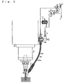
- Fig. 5 shows a modified example of the above embodiment.
- the mist generating device 13 is located around the spindle 8.
- the mist generating device 13 mixes the compressed air fed from the feed line 6 and the coolant fed from the feed line 7, producing a coolant mist at the tip. Then, it spouts the mist toward a portion to be cut by the cutting edge 49.
- valve 23 is not provided to a coolant inflow portion of the mist generating device 13, it may be given at need.
- the feed lines 6, 7 around the spindle 8 are connected to a joint 100 fixed on the holding cylinder 9, and from the joint 100 they are elongated to connect to the mist generating device 13 through a deformable double tube 101.
- a central path 101a of the double tube 101 is for the coolant, while a looped path 101b around it is for the compressed air.
- the present invention has the following effects.
- the means for sucking and discharging the coolant lowers the coolant pressure within the feed line by sucking a fixed amount of coolant. Accordingly, usual liquid dropping and related various bad influences are prevented.
- the coolant sucking and delivering means lowers the coolant pressure within the feed line by sucking a fixed amount of coolant, thereby closing the valve means at once. Accordingly, usual liquid dropping and related various bad influences are prevented.
- the coolant sucking and delivering means raises the coolant pressure by spouting a fixed amount of coolant sucked into the feed line previously. Therefore, the valve means opens at once, and then the coolant is fed into the mist generating device. Accordingly, a time-lag between the onset of feeding the coolant from the feed pump and production of the mist by the mist generating device is diminished.
- the coolant inside the feed line can be sucked and discharged by simple and firm mechanism.
- the feed means for the compressed air which is necessary to produce the mist, can be partially used as a driving coolant sucking and delivering means, and therefor its mechanism is simplified. Besides, feed of the compressed air into the mist generating device can be connected to drive of the coolant sucking and delivering means without any complicated control device.
Landscapes
- Engineering & Computer Science (AREA)
- Mechanical Engineering (AREA)
- Physics & Mathematics (AREA)
- Fluid Mechanics (AREA)
- Auxiliary Devices For Machine Tools (AREA)
Abstract
Description
- This invention relates to a coolant feeding device of a machine tool.
- Prior art references (such as the Japanese Patent Publication No. 66437 of 1997) have disclosed machine tools that feed coolant from a feed pump to a mist generating device at the tip of a spindle through a feed line, and that is provided with a valve means at a coolant inflow portion of the mist generating device. Here, the valve means is to close a coolant path when coolant pressure within the feed line lowers below a fixed level.
- In the above conventional machine tools, compressed air is mingled with the coolant inside the feed line, fed from the mist generating device. When the feed pump stops feeding the coolant, compressed air pressure lowers, and then the air expands, thereby causing a little coolant leakage out of the valve means (this phenomenon is called liquid dropping).
- The liquid dropping is a waste of coolant. Besides, it widens a time-lag between the onset of the feed pump and mist production by the mist generating device. Moreover, when generating mist again, the coolant which remains in the mist generating device may spout at a stretch, thereby polluting a work piece and a working environment.
- An object of this invention is to provide a coolant feeding device of the machine tool that can solve the above problems.
- To achieve the above object, the present invention is characterized by a machine tool that feeds coolant from a feed pump to a mist generating device on the tip of a spindle by way of a feed line. In this machine tool, a cylinder chamber for compressed air and a cylinder chamber for coolant are provided oppositely. Besides, pistons (30) (31) are provided to the cylinder chambers (28) (29), respectively, and integrated into one body. Moreover, a coolant sucking and delivering means is provided with a compression spring to press the pistons in a specific direction for each cylinder chamber. The means sucks a fixed amount of coolant in the feed line, when the feed pump stops feeding the coolant. Furthermore, the means feeds a fixed amount of coolant into the feed line, when the feed pump begins feeding the coolant.
- When the above coolant sucking and delivering means sucks the coolant, the coolant pressure within the feed line lowers at a stretch. Accordingly, usual liquid dropping is prevented.
- Beside, when the coolant sucking and delivering means spouts the coolant, the coolant pressure within the feed line rises at a stretch. Accordingly, the coolant is immediately fed into the mist generating device in connection with the onset of coolant feed from the feed pump, thereby bring about a good response of mist generation.
- This invention can be materialized as follows.
- At a coolant inflow part of the mist generating device is provided a valve means that is closed when the coolant pressure within the feed line is below a fixed level. The valve means is closed immediately, when the feed pump stops feeding the coolant. Therefore, usual liquid dropping is prevented more certainly. On the other hand, when the feed pump begins feeding the coolant, the valve means is open immediately. This enables rapid mist generation.
- Besides, the coolant sucking and delivering means sucks the coolant inside the feed line into the cylinder chamber at need, and discharges the sucked coolant into the feed line at need. According to this means, sucking and discharging coolant is easy.
- Moreover, the piston is driven by a compressed air fed into the mist generating device for producing mist. Since the compressed air for producing the mist is used for driving the piston, driving mechanism for the piston is simplified.
-
- Fig. 1 is a view showing the main part of a machine tool according to this invention.
- Fig. 2 is an explanatory view diagraming the main part of the machine tool.
- Fig. 3 is a sectional view showing surroundings of a mist generating device of the machine tool according to this invention.
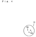
- Fig. 4 is a front view showing a part of a coolant injection nozzle of the mist generating device.
- Fig. 5 shows a modification of the above embodiment.
-
- A detailed explanation follows about embodiments of the present invention with reference to drawings.
- In the drawings, 1 is a spindle unit, 2 is a coolant sucking and delivering means, 3 is a coolant tank, 4 is a feed pump, 5 is a source for compressed air, 6 is a feed line for compressed air, and 7 is a feed line.
- The spindle unit 1 comprises a
spindle 8, apulley 10, aclamp actuator 12 and a rotatingjoint 14. Thespindle 8 is rotatably held in a holding cylinder 9 for the spindle. On the rear of thespindle 8 is fixed thepulley 10, into which rotational motive power is input. Theclamp actuator 12 is provided on the rear end of thespindle 8 to clamp or unclamp a pull-stud 11a at the rear end of atool holder 11, which is fixed on the tip end of thespindle 8. The rotatingjoint 14 is provided on the rear of theactuator 12 to feed the coolant and the compressed air from the outside of thespindle 8 into a mist generatingdevice 13, which is provided inside the tip of thespindle 8. - The
mist generating device 13 is integrated into acylindrical holder 16, which engages with aclamp 15 to clamp the pull-stud 11a. A detailed explanation will follow. - As shown in Fig. 3, a
mist discharge cylinder 17, acompression spring 18, acylindrical valve 19, a mist generatingcylinder 20, and acoolant injection nozzle 21 are arranged inside an inner hole of thecylinder member 16 in this order from the front thereof. - The
discharge cylinder 17 is provided with a flange 17a on its rear end. The flange 17a is engaged with a stage 16a of the inner hole of thecylindrical holder 16, thereby preventing thedischarge cylinder 17 from coming out to the forward f1, and contacting the tip face of thedischarge cylinder 17 to the rear face of the pull-stud 11a. - The
cylindrical valve 19 is provided with a stage 19a on its circumferential face, and pressed backward by thecompression spring 18 which is situated between the stage 19a and the rear face of thedischarge cylinder 17. Here, thecylindrical valve 19 is closed when the rear face 19b contacts to the front face of themist generating cylinder 20, and open when the rear face 19b is away therefrom. - The mist generating
cylinder 20 is a cylindrical member, provided with a longitudinal air path groove 20a on the circumferential face of themist generating cylinder 20, amist exit hole 20b having a comparative large diameter at the inner front, and a rearinner hole 20c at the inner rear thereof, into which a front 21a of the injectingnozzle 21 is inserted. Theinner hole 20c communicates with the air path groove 20a through a side hole 20d, and with theexit hole 20b through apath 20e having a comparative small diameter. Therefore, backward displacement of themist generating cylinder 20 are prevented by the injectingnozzle 21. - The injecting
nozzle 21 is provided with aflange 21b on the rear circumferential face of the front 21a. The rear of theflange 21b is fluid-tightly inserted into the tip of a straightcoolant feed pipe 22. Besides, at the center of the injectingnozzle 21 is provided astepped path 21c whose rear is open. As shown in Fig. 4, the front wall of thepath 21c is provided with three injection holes 21d. Here, thefeed pipe 22 is integrated with thespindle 8 to control backward displacement of the injectingnozzle 21. - The rear of the
path 21c is an inflow part for the coolant from thefeed pipe 22, and here is provided a valve means 23. Concretely, acompression spring 24 is inserted into thepath 21c, and its front end is engaged with a stage "a" of thepath 21c. Besides, aglobe 25 is provided to the rear end of thecompression spring 24, and a cylindrical valve seat 26, which closely fits into the feed pipe 22e, is inserted into thepath 21c on the rear of theglobe 25. Here, theglobe 25 closes a front opening of the cylindrical valve seat 26. Moreover, a notch 27 is formed relative to the position of theglobe 25. When the coolant pressure is over the fixed level within thefeed pipe 22, theglobe 25 is forwardly displaced against elasticity of thespring 18, thereby opening the coolant path. Hence, the coolant flows to the side of thespring 18 from the valve seat 26 through the notch 27. Conversely, when the coolant pressure lowers below the fixed level within thefeed pipe 22, theglobe 25 is backwardly displaced by the elasticity of thespring 18. Accordingly, the coolant path is closed, and the flowing of the coolant stops. - The
means 2 for sucking and discharging coolant has the following constructions. Acylinder chamber 28 for the compressed air and acylinder chamber 29 for the coolant are formed oppositely, andpistons cylinder chambers pistons compression spring 32 is provided to ,press thesepistons cylinder chambers - The feed pump 4 has the same construction as the
means 2. Acylinder chamber 33 for the coolant and acylinder chamber 34 for the compressed air are formed oppositely, andpistons cylinder chambers pistons compression spring 37 is provided to press thesepistons cylinder chamber - The
feed line 6 for the compressed air connects to an upper closed space 3a of thecoolant tank 3 and aninlet 14a for the compressed air of the joint 14 through adirection diverter 38 as well as apressure adjusting device 39. Besides, thefeed line 6 diverges before theinlet 14a, and its branch connects to thecylinder chamber 29 through adischarge regulator 40. Thefeed line 6 reaches the air groove 20a of themist generating device 13 from theinlet 14a through acompressed air path 41 which surrounds thefeed pipe 22. Moreover, thefeed line 6 also diverges at the upper stream of thediverter 38, and its branch connects to thecylinder chamber 34 through adirection diverter 42. - In this case, the adjusting
device 39 has apressure control valve 43 to adjust feed pressure of the compressed air, and acheck valve 44 to permit the compressed air in thefeed line 6 on thespindle 8 side to flow into thediverter 38. Besides, theregulator 40 has adischarge control valve 45 to adjust a feed rate of the compressed air flowing into thecylinder chamber 28, and acheck valve 46 to permit the compressed air to flow out of thecylinder chamber 28. - The feed line 7 connects the bottom of the
tank 3 to a suction hole of thecylinder chamber 33. Besides, it connects a discharge hole of thecylinder chamber 33 to a coolant inlet 14b of the joint 14. Moreover, the feed line 7 diverges before the inlet 14b, and its branch connects to thecylinder chamber 29 for coolant. Furthermore, the feed line 7 reaches the inflow part of themist generating device 13 from the inlet 14b through thestraight feed pipe 22. - Here, 47 is a silencer to reduce a noise due to the compressed air flowing out of the
diverters tool holder 11. - A working example and actions of the machine tool will be explained as follows.
- The
spindle 8 rotates, when rotations are transmitted to thepulley 12 by a not-illustrated motor. During its rotations, when thediverter 38 is turned to the feed side of the compressed air, the compressed air reaches the groove 20a through the joint 14 and thecompressed air path 41 of thespindle 8, and then flows into theinner hole 20c through the side hole 20d. Subsequently, the compressed air spouts toward theexit hole 20b through thepath 20e at high speed. During this process, the compressed air is flowing into thecylinder chamber 28, thereby displacing thepiston 30 toward thepiston 31 against elasticity of thespring 32. Accordingly, thecylinder chamber 29 minimizes its capacity. - At the same time as switching over the
diverter 38, theother diverter 42 is repeatedly reciprocated between a feed side and an outflow side of the compressed air at proper intervals. When thediverter 42 is turned to the feed side, the compressed air is fed into thecylinder chamber 34, thereby pressing thepiston 36 toward thepiston 35 against elasticity of thespring 37. On the other hand, when thediverter 42 is turned to the outflow side, the compressed air flows out of thecylinder chamber 34, thereby displacing thepiston 35 in a pressing direction of thespring 37 by its elasticity. - Since the
piston 35 is displaced in connection with thepiston 36, thecylinder chamber 33 sucks the coolant inside thetank 3 and discharges that, repeatedly. The discharged coolant reaches thevalve 23 of themist generating device 13 through the joint 14 and thestraight feed pipe 22. When the forward displacement power of theglobe 25 due to the coolant pressure is larger than elasticity of thespring 24, theglobe 25 is pressed forward, thereby opening thevalve 23. Accordingly, the coolant reaches the front of theinner hole 21c through thevalve 23, and then spouts from here through the injection hole 21d. - The spouted coolant is heavily mixed with the compressed air in front of the injection hole 21d, and then made into mist. The mist reaches the rear end of the pull-stud 11a of the
tool holder 11 through theexit hole 20e, and inner holes of thecylindrical valve 19 and thedischarge cylinder 17. The mist spouts outside from a tip opening of thecutting edge 49 through central holes of thetool holder 11 and thecutting edge 49, lubricating a cut part of a work piece "w" during machining it. Besides, when the mist pressure lowers below the fixed level within the inner hole of thedischarge cylinder 17, thecylindrical valve 19 becomes unbalanced in a longitudinal direction, and is displaced forward against elasticity of thespring 18. Therefore, the rear end of thecylindrical valve 19 is separated from the tip of themist generating cylinder 20, and then through a gap therebetween the compressed air inside the groove 20a flows into an inner hole of thedischarge cylinder 20. - During producing the above-mentioned mist, when the
diverter 38 is turned to the outflow side, feed of the compressed air into themist generating device 13 stops immediately. Besides, operation of the feed pump 4 also stops, thereby preventing coolant feed into the feed line 7. - On the other hand, since the compressed air in the
cylinder chamber 28 escapes from thediverter 38, thepiston 31 in thecylinder chamber 29 is displaced by elasticity of thespring 32. Due to this displacement, a fixed amount of coolant is sucked from the feed line 7, thereby lowering the coolant pressure within thefeed pipe 22 at a stretch. Therefore, thevalve 23 is closed right after feed of the compressed air stops, thereby preventing the coolant inside thefeed pipe 22 from flowing out of thevalve 23 into themist generating device 13. Accordingly, no liquid drops like in the conventional machine tools. - Next, when the
diverter 38 is turned to the feed side of the compressed air again under a state that feed of the compressed air stops, the compressed air is fed into themist generating device 13 through thefeed line 6 as is mentioned in the above. This compressed air is fed into thecylinder chamber 28 of themeans 2, displacing thepiston 30 toward thepiston 31 against elasticity of thespring 32. Due to this displacement, a fixed amount of previously sucked coolant is extruded from thecylinder chamber 29, and then the extruded coolant is fed into the feed line 7. - Therefore, the coolant pressure in the feed line 7 on the upper stream of the
valve 23 rises at a stretch in connection with feed of the compressed air, and this risen pressure opens thevalve 23 immediately. Thereafter, the coolant fed from the feed pump 4 reaches the injection hole 21d through thevalve 23. Then, the coolant is made into a mist, and spouted from the tip of thecutting edge 49. - In the above operation, the
check valve 46 hastens outflow of the compressed air in thecylinder chamber 28 and thefeed line 6 toward the air. Besides, thecontrol valve 45 changes inflow velocity of the compressed air into thecylinder chamber 28, and adjusts outflow velocity of the coolant from thecylinder chamber 29 on the onset of feeding the compressed air into thefeed line 6. Hence, thecontrol valve 45 changes a speed in increasing pressure of the coolant inside the feed line 7. - In the above embodiment, the feed pump 4 can be of an optional mechanism. For example, the
piston 36 in thecylinder chamber 34 can be driven by an electric motor or compressed air irrelevant to thefeed line 6. - Fig. 5 shows a modified example of the above embodiment. Here, the
mist generating device 13 is located around thespindle 8. Themist generating device 13 mixes the compressed air fed from thefeed line 6 and the coolant fed from the feed line 7, producing a coolant mist at the tip. Then, it spouts the mist toward a portion to be cut by thecutting edge 49. - In this case, though the
above valve 23 is not provided to a coolant inflow portion of themist generating device 13, it may be given at need. - The feed lines 6, 7 around the
spindle 8 are connected to a joint 100 fixed on the holding cylinder 9, and from the joint 100 they are elongated to connect to themist generating device 13 through a deformabledouble tube 101. Here, a central path 101a of thedouble tube 101 is for the coolant, while a looped path 101b around it is for the compressed air. - The present invention has the following effects.
- According to claim 1, right after the feed pump stops feeding the coolant, the means for sucking and discharging the coolant lowers the coolant pressure within the feed line by sucking a fixed amount of coolant. Accordingly, usual liquid dropping and related various bad influences are prevented.
- According to
claim 2, right after the feed pump stops feeding the coolant, the coolant sucking and delivering means lowers the coolant pressure within the feed line by sucking a fixed amount of coolant, thereby closing the valve means at once. Accordingly, usual liquid dropping and related various bad influences are prevented. - Besides, as soon as the feed pump begins feeding the coolant again, the coolant sucking and delivering means raises the coolant pressure by spouting a fixed amount of coolant sucked into the feed line previously. Therefore, the valve means opens at once, and then the coolant is fed into the mist generating device. Accordingly, a time-lag between the onset of feeding the coolant from the feed pump and production of the mist by the mist generating device is diminished.
- According to
claim 3, the coolant inside the feed line can be sucked and discharged by simple and firm mechanism. - According to claim 4, the feed means for the compressed air, which is necessary to produce the mist, can be partially used as a driving coolant sucking and delivering means, and therefor its mechanism is simplified. Besides, feed of the compressed air into the mist generating device can be connected to drive of the coolant sucking and delivering means without any complicated control device.
Claims (4)
- A coolant feeding device of a machine tool that feeds the coolant from a feed pump (4) to a mist generating device (13) on the tip of a spindle (8) by way of a feed line (7):wherein a cylinder chamber (28) for compressed air and a cylinder chamber (29) for coolant are provided oppositely;wherein pistons (30) (31) are provided to said cylinder chambers (28) (29), respectively, and integrated into one body;wherein a coolant sucking and delivering means (2) is provided with a compression spring (32) to press said pistons in a specific direction for each cylinder chamber;wherein said means (2) sucks a fixed amount of coolant in the feed line (7), when the feed pump (4) stops feeding the coolant; andwherein said means (2) feeds a fixed amount of coolant into the feed line (7), when the feed pump (4) begins feeding the coolant.
- A coolant feeding device of a machine tool that feeds the coolant from a feed pump (4) to a mist generating device (13) on the tip of a spindle (8) by way of a feed line (7), and that has a valve means (23) at an inflow part for coolant of said mist generating device (13) to be closed when the coolant pressure within said feed line (7) lowers below a fixed level:wherein a cylinder chamber (28) for compressed air and a cylinder chamber (29) for coolant are provided oppositely;wherein pistons (30) (31) are provided to said cylinder chambers (28) (29), respectively, and integrated into one body;wherein a coolant sucking and delivering means (2) is provided with a compression spring (32) to press said pistons in a specific direction for each cylinder chamber;wherein said means (2) sucks a fixed amount of coolant in the feed line (7), when the feed pump (4) stops feeding the coolant; andwherein said means (2) feeds a fixed amount of coolant into the feed line (7), when the feed pump (4) begins feeding the coolant.
- A coolant feeding device of a machine tool as set forth in claim 1 or 2, wherein said means (2) sucks the coolant from the feed line (7) into the cylinder chamber (29), and spouts the coolant into the feed line at need.
- A coolant feeding device of a machine tool as set forth in claim 1 or 2, wherein said piston (31) provided to the cylinder chamber (29) is driven by compressed air to be fed into the mist generating device (13) for producing mist.
Applications Claiming Priority (5)
| Application Number | Priority Date | Filing Date | Title |
|---|---|---|---|
| JP11260199 | 1999-04-20 | ||
| JP11112601A JP3087119B1 (en) | 1999-04-20 | 1999-04-20 | Cutting fluid supply device for machine tools |
| PCT/JP2000/002523 WO2000062973A1 (en) | 1999-04-20 | 2000-04-17 | Coolant feeding device of machine tool |
| CN00107896A CN1116148C (en) | 1999-04-20 | 2000-07-10 | Cutting liquid feeder for machine tool |
| CA002316557A CA2316557C (en) | 1999-04-20 | 2000-08-21 | Device for supplying coolant of machine tool |
Publications (3)
| Publication Number | Publication Date |
|---|---|
| EP1172173A1 true EP1172173A1 (en) | 2002-01-16 |
| EP1172173A4 EP1172173A4 (en) | 2002-10-16 |
| EP1172173B1 EP1172173B1 (en) | 2003-08-06 |
Family
ID=27171331
Family Applications (1)
| Application Number | Title | Priority Date | Filing Date |
|---|---|---|---|
| EP00917342A Expired - Lifetime EP1172173B1 (en) | 1999-04-20 | 2000-04-17 | Coolant feeding device of machine tool |
Country Status (6)
| Country | Link |
|---|---|
| EP (1) | EP1172173B1 (en) |
| JP (1) | JP3087119B1 (en) |
| CN (1) | CN1116148C (en) |
| CA (1) | CA2316557C (en) |
| TW (1) | TW460363B (en) |
| WO (1) | WO2000062973A1 (en) |
Cited By (3)
| Publication number | Priority date | Publication date | Assignee | Title |
|---|---|---|---|---|
| US6639780B1 (en) * | 1999-04-28 | 2003-10-28 | Shinsuke Sugata | Coolant feeding device of machine tool |
| EP1514637A3 (en) * | 2003-09-11 | 2006-06-07 | Airbus Deutschland GmbH | Device for supplying lubricant to cutting tools |
| US9616540B2 (en) | 2011-02-08 | 2017-04-11 | The University Of Utah Research Foundation | System and method for dispensing a minimum quantity of cutting fluid |
Families Citing this family (11)
| Publication number | Priority date | Publication date | Assignee | Title |
|---|---|---|---|---|
| JP3608152B2 (en) | 2000-05-26 | 2005-01-05 | ホーコス株式会社 | Automatic cutting fluid supply device |
| JP4986352B2 (en) * | 2001-09-05 | 2012-07-25 | 株式会社安永 | Oil mist supply system |
| DE10345130A1 (en) * | 2003-09-26 | 2005-04-21 | Vogel Willi Ag | Aerosol device for lubricating and/or cooling of tools or workpieces has fluid selecting unit with branch from flow path which can be transferred from operating position to bypass position |
| CN100513067C (en) * | 2005-05-30 | 2009-07-15 | 铨宝工业股份有限公司 | Cutting fluid nozzle for use with a machine tool |
| CN101745833B (en) * | 2008-12-16 | 2013-03-20 | 武汉重型机床集团有限公司 | Inner-cooling automatic tool-broaching mechanism of spindle of boring bar |
| CN102448666B (en) * | 2009-05-27 | 2014-02-12 | 报国株式会社 | Cutting liquid supply device for machine tool |
| CN103447881B (en) * | 2013-09-17 | 2016-05-18 | 江苏新瑞重工科技有限公司 | Digit Control Machine Tool pentahedron central water outlet right-angle head |
| TWI636850B (en) * | 2017-04-28 | 2018-10-01 | 忠源實業股份有限公司 | Center machine for processing machine |
| JP6603286B2 (en) * | 2017-10-20 | 2019-11-06 | ファナック株式会社 | Cutting fluid supply device for machine tools |
| CN109084162B (en) * | 2018-10-31 | 2023-09-26 | 四川大学 | Optional lubrication systems and lubrication methods for cutting fluids |
| CN110509095B (en) * | 2019-08-29 | 2022-02-01 | 全准数控设备(苏州)有限公司 | Flushing unit for tool changing mechanism of processing machine and quick tool changing method |
Family Cites Families (2)
| Publication number | Priority date | Publication date | Assignee | Title |
|---|---|---|---|---|
| JP2965468B2 (en) * | 1994-10-19 | 1999-10-18 | 株式会社牧野フライス製作所 | Processing fluid supply device |
| JP2687110B2 (en) * | 1995-08-30 | 1997-12-08 | ホーコス株式会社 | Spindle device of machine tool |
-
1999
- 1999-04-20 JP JP11112601A patent/JP3087119B1/en not_active Expired - Lifetime
-
2000
- 2000-04-17 WO PCT/JP2000/002523 patent/WO2000062973A1/en not_active Ceased
- 2000-04-17 EP EP00917342A patent/EP1172173B1/en not_active Expired - Lifetime
- 2000-06-30 TW TW089112965A patent/TW460363B/en not_active IP Right Cessation
- 2000-07-10 CN CN00107896A patent/CN1116148C/en not_active Expired - Fee Related
- 2000-08-21 CA CA002316557A patent/CA2316557C/en not_active Expired - Fee Related
Non-Patent Citations (2)
| Title |
|---|
| No further relevant documents disclosed * |
| See also references of WO0062973A1 * |
Cited By (3)
| Publication number | Priority date | Publication date | Assignee | Title |
|---|---|---|---|---|
| US6639780B1 (en) * | 1999-04-28 | 2003-10-28 | Shinsuke Sugata | Coolant feeding device of machine tool |
| EP1514637A3 (en) * | 2003-09-11 | 2006-06-07 | Airbus Deutschland GmbH | Device for supplying lubricant to cutting tools |
| US9616540B2 (en) | 2011-02-08 | 2017-04-11 | The University Of Utah Research Foundation | System and method for dispensing a minimum quantity of cutting fluid |
Also Published As
| Publication number | Publication date |
|---|---|
| TW460363B (en) | 2001-10-21 |
| JP3087119B1 (en) | 2000-09-11 |
| CA2316557A1 (en) | 2002-02-21 |
| WO2000062973A1 (en) | 2000-10-26 |
| EP1172173B1 (en) | 2003-08-06 |
| CN1333106A (en) | 2002-01-30 |
| CA2316557C (en) | 2004-11-02 |
| JP2000301428A (en) | 2000-10-31 |
| CN1116148C (en) | 2003-07-30 |
| EP1172173A4 (en) | 2002-10-16 |
Similar Documents
| Publication | Publication Date | Title |
|---|---|---|
| EP1172173B1 (en) | Coolant feeding device of machine tool | |
| US6123270A (en) | Work machining method and apparatus for supplying mist used therein | |
| JPH0966437A (en) | Machine tool spindle device | |
| US6702199B1 (en) | Coolant feeding device of machine tool | |
| US5878632A (en) | Automatic transmission, in particular for motor vehicles | |
| US6639780B1 (en) | Coolant feeding device of machine tool | |
| CN113613818A (en) | Dustproof mechanism of chuck and chuck | |
| JPH08118198A (en) | Processing liquid supply device | |
| JPH10235507A (en) | Drilling method and drilling device | |
| US7214012B2 (en) | Multi-shaft spindle head of machine tool | |
| WO2002064310A1 (en) | Main shaft device for machine tools | |
| JP2000210836A (en) | Spindle device for machine tools | |
| EP0988927A2 (en) | A method of machining a workpiece and apparatus for supplying mist used therein | |
| JP3728501B2 (en) | Method and apparatus for supplying processing mist oil | |
| KR200344229Y1 (en) | Cutting oil and air supplying Apparatus for NC machine | |
| JPH0751984A (en) | Coolant supply device | |
| KR100376672B1 (en) | Engine oil feed system for vehicles | |
| JP3038778U (en) | Mist generator | |
| KR20050054219A (en) | Cutting oil and air supplying apparatus for nc machine | |
| JP2006055988A (en) | Lubricant feeder | |
| CN117605716A (en) | A jet siphon drainage device and bearing lubrication hydraulic system | |
| JP2000233301A (en) | Refueling device for bar feeder | |
| EP1593901A1 (en) | Device for damping a fluid flow | |
| JP2001150293A (en) | Liquid supply device | |
| JP2002103176A (en) | Oil injection nozzle and oil supply device |
Legal Events
| Date | Code | Title | Description |
|---|---|---|---|
| PUAI | Public reference made under article 153(3) epc to a published international application that has entered the european phase |
Free format text: ORIGINAL CODE: 0009012 |
|
| 17P | Request for examination filed |
Effective date: 20010910 |
|
| AK | Designated contracting states |
Kind code of ref document: A1 Designated state(s): AT BE CH CY DE DK ES FI FR GB GR IE IT LI LU MC NL PT SE |
|
| A4 | Supplementary search report drawn up and despatched |
Effective date: 20020829 |
|
| AK | Designated contracting states |
Kind code of ref document: A4 Designated state(s): CH DE ES FR GB IT LI |
|
| GRAH | Despatch of communication of intention to grant a patent |
Free format text: ORIGINAL CODE: EPIDOS IGRA |
|
| GRAH | Despatch of communication of intention to grant a patent |
Free format text: ORIGINAL CODE: EPIDOS IGRA |
|
| GRAA | (expected) grant |
Free format text: ORIGINAL CODE: 0009210 |
|
| AK | Designated contracting states |
Designated state(s): CH DE ES FR GB IT LI |
|
| REG | Reference to a national code |
Ref country code: GB Ref legal event code: FG4D |
|
| REG | Reference to a national code |
Ref country code: CH Ref legal event code: EP |
|
| REG | Reference to a national code |
Ref country code: CH Ref legal event code: NV Representative=s name: ISLER & PEDRAZZINI AG |
|
| REG | Reference to a national code |
Ref country code: IE Ref legal event code: FG4D |
|
| REF | Corresponds to: |
Ref document number: 60004347 Country of ref document: DE Date of ref document: 20030911 Kind code of ref document: P |
|
| REG | Reference to a national code |
Ref country code: ES Ref legal event code: FG2A Ref document number: 2199809 Country of ref document: ES Kind code of ref document: T3 |
|
| ET | Fr: translation filed | ||
| PLBE | No opposition filed within time limit |
Free format text: ORIGINAL CODE: 0009261 |
|
| STAA | Information on the status of an ep patent application or granted ep patent |
Free format text: STATUS: NO OPPOSITION FILED WITHIN TIME LIMIT |
|
| 26N | No opposition filed |
Effective date: 20040507 |
|
| REG | Reference to a national code |
Ref country code: IE Ref legal event code: MM4A |
|
| REG | Reference to a national code |
Ref country code: CH Ref legal event code: PCAR Free format text: ISLER & PEDRAZZINI AG;POSTFACH 1772;8027 ZUERICH (CH) |
|
| REG | Reference to a national code |
Ref country code: FR Ref legal event code: PLFP Year of fee payment: 17 |
|
| REG | Reference to a national code |
Ref country code: FR Ref legal event code: PLFP Year of fee payment: 18 |
|
| REG | Reference to a national code |
Ref country code: FR Ref legal event code: PLFP Year of fee payment: 19 |
|
| PGFP | Annual fee paid to national office [announced via postgrant information from national office to epo] |
Ref country code: GB Payment date: 20190326 Year of fee payment: 20 Ref country code: FR Payment date: 20190320 Year of fee payment: 20 |
|
| PGFP | Annual fee paid to national office [announced via postgrant information from national office to epo] |
Ref country code: DE Payment date: 20190318 Year of fee payment: 20 Ref country code: ES Payment date: 20190503 Year of fee payment: 20 Ref country code: IT Payment date: 20190412 Year of fee payment: 20 |
|
| PGFP | Annual fee paid to national office [announced via postgrant information from national office to epo] |
Ref country code: CH Payment date: 20190425 Year of fee payment: 20 |
|
| REG | Reference to a national code |
Ref country code: DE Ref legal event code: R071 Ref document number: 60004347 Country of ref document: DE |
|
| REG | Reference to a national code |
Ref country code: CH Ref legal event code: PL |
|
| REG | Reference to a national code |
Ref country code: GB Ref legal event code: PE20 Expiry date: 20200416 |
|
| REG | Reference to a national code |
Ref country code: ES Ref legal event code: FD2A Effective date: 20200724 |
|
| PG25 | Lapsed in a contracting state [announced via postgrant information from national office to epo] |
Ref country code: GB Free format text: LAPSE BECAUSE OF EXPIRATION OF PROTECTION Effective date: 20200416 |
|
| PG25 | Lapsed in a contracting state [announced via postgrant information from national office to epo] |
Ref country code: ES Free format text: LAPSE BECAUSE OF EXPIRATION OF PROTECTION Effective date: 20200418 |