EP1172070A1 - Ablation catheter with electrode temperature monitoring - Google Patents
Ablation catheter with electrode temperature monitoring Download PDFInfo
- Publication number
- EP1172070A1 EP1172070A1 EP01305876A EP01305876A EP1172070A1 EP 1172070 A1 EP1172070 A1 EP 1172070A1 EP 01305876 A EP01305876 A EP 01305876A EP 01305876 A EP01305876 A EP 01305876A EP 1172070 A1 EP1172070 A1 EP 1172070A1
- Authority
- EP
- European Patent Office
- Prior art keywords
- electrode
- catheter
- thermocouples
- monitoring circuit
- junction
- Prior art date
- Legal status (The legal status is an assumption and is not a legal conclusion. Google has not performed a legal analysis and makes no representation as to the accuracy of the status listed.)
- Granted
Links
Images

Classifications
-
- A—HUMAN NECESSITIES
- A61—MEDICAL OR VETERINARY SCIENCE; HYGIENE
- A61B—DIAGNOSIS; SURGERY; IDENTIFICATION
- A61B18/00—Surgical instruments, devices or methods for transferring non-mechanical forms of energy to or from the body
- A61B18/04—Surgical instruments, devices or methods for transferring non-mechanical forms of energy to or from the body by heating
- A61B18/12—Surgical instruments, devices or methods for transferring non-mechanical forms of energy to or from the body by heating by passing a current through the tissue to be heated, e.g. high-frequency current
- A61B18/14—Probes or electrodes therefor
- A61B18/1492—Probes or electrodes therefor having a flexible, catheter-like structure, e.g. for heart ablation
-
- A—HUMAN NECESSITIES
- A61—MEDICAL OR VETERINARY SCIENCE; HYGIENE
- A61B—DIAGNOSIS; SURGERY; IDENTIFICATION
- A61B18/00—Surgical instruments, devices or methods for transferring non-mechanical forms of energy to or from the body
- A61B18/04—Surgical instruments, devices or methods for transferring non-mechanical forms of energy to or from the body by heating
- A61B18/12—Surgical instruments, devices or methods for transferring non-mechanical forms of energy to or from the body by heating by passing a current through the tissue to be heated, e.g. high-frequency current
- A61B18/14—Probes or electrodes therefor
-
- A—HUMAN NECESSITIES
- A61—MEDICAL OR VETERINARY SCIENCE; HYGIENE
- A61B—DIAGNOSIS; SURGERY; IDENTIFICATION
- A61B18/00—Surgical instruments, devices or methods for transferring non-mechanical forms of energy to or from the body
- A61B2018/00053—Mechanical features of the instrument of device
- A61B2018/00214—Expandable means emitting energy, e.g. by elements carried thereon
-
- A—HUMAN NECESSITIES
- A61—MEDICAL OR VETERINARY SCIENCE; HYGIENE
- A61B—DIAGNOSIS; SURGERY; IDENTIFICATION
- A61B18/00—Surgical instruments, devices or methods for transferring non-mechanical forms of energy to or from the body
- A61B2018/00636—Sensing and controlling the application of energy
- A61B2018/00642—Sensing and controlling the application of energy with feedback, i.e. closed loop control
- A61B2018/00654—Sensing and controlling the application of energy with feedback, i.e. closed loop control with individual control of each of a plurality of energy emitting elements
-
- A—HUMAN NECESSITIES
- A61—MEDICAL OR VETERINARY SCIENCE; HYGIENE
- A61B—DIAGNOSIS; SURGERY; IDENTIFICATION
- A61B18/00—Surgical instruments, devices or methods for transferring non-mechanical forms of energy to or from the body
- A61B2018/00636—Sensing and controlling the application of energy
- A61B2018/00773—Sensed parameters
- A61B2018/00791—Temperature
- A61B2018/00797—Temperature measured by multiple temperature sensors
-
- A—HUMAN NECESSITIES
- A61—MEDICAL OR VETERINARY SCIENCE; HYGIENE
- A61B—DIAGNOSIS; SURGERY; IDENTIFICATION
- A61B18/00—Surgical instruments, devices or methods for transferring non-mechanical forms of energy to or from the body
- A61B2018/00636—Sensing and controlling the application of energy
- A61B2018/00773—Sensed parameters
- A61B2018/00791—Temperature
- A61B2018/00821—Temperature measured by a thermocouple
-
- A—HUMAN NECESSITIES
- A61—MEDICAL OR VETERINARY SCIENCE; HYGIENE
- A61B—DIAGNOSIS; SURGERY; IDENTIFICATION
- A61B18/00—Surgical instruments, devices or methods for transferring non-mechanical forms of energy to or from the body
- A61B2018/00636—Sensing and controlling the application of energy
- A61B2018/00898—Alarms or notifications created in response to an abnormal condition
-
- A—HUMAN NECESSITIES
- A61—MEDICAL OR VETERINARY SCIENCE; HYGIENE
- A61B—DIAGNOSIS; SURGERY; IDENTIFICATION
- A61B18/00—Surgical instruments, devices or methods for transferring non-mechanical forms of energy to or from the body
- A61B18/04—Surgical instruments, devices or methods for transferring non-mechanical forms of energy to or from the body by heating
- A61B18/12—Surgical instruments, devices or methods for transferring non-mechanical forms of energy to or from the body by heating by passing a current through the tissue to be heated, e.g. high-frequency current
- A61B18/1206—Generators therefor
- A61B2018/124—Generators therefor switching the output to different electrodes, e.g. sequentially
Definitions
- the present invention concerns catheters used for the treatment of cardiac arrhythmias. More specifically, the present invention relates to a novel ablation catheter having an electrode temperature monitoring system.
- Cardiac arrhythmias are often caused when portions of the heart form alternative conduction pathways which transmit electrical signals that interfere with the normal conduction of electrical signals which regulate the beating of the heart.
- the cells which comprise these alternative conduction pathways must either be destroyed or the conductive pathways from these cells be blocked from transmitting electrical signals to the rest of the heart.
- Radio Frequency Ablation The procedure entails first mapping the heart in order to determine where these alternative conduction pathways are located. Once these alternative conduction pathways are located, radio frequency (RF) waves are then used to create lesions in the heart which either destroys the cells that comprise these alternative conduction pathways or which blocks the conduction of electrical signals from these cells.
- RF Radio Frequency
- RFA typically involves the use of specialized ablation catheters which are designed to be inserted vascularly into a person and maneuvered into the heart. These ablation catheters carry electrodes which transmit RF waves to the tissues at an application site. The RF waves generate heat at the application site which in turn causes the cells at the application site to rupture forming a lesion in the heart tissue.
- a common problem among prior art ablation catheters is the formation of coagulum around the electrodes during an RFA.
- both the electrode and the surrounding tissue are heated.
- the heat generated by the RF waves sometimes cause the electrode to overheat, causing the blood surrounding the electrode to coagulate on the electrode.
- the coagulum that collects on the electrode causes the impedance between the electrode and the application site to increase thereby reducing the effectiveness of the electrode to deliver the RF waves.
- ablation catheters which currently have multiple electrodes for delivering RF energy to an application site. Many of these catheters deliver RF energy by sequentially activating the electrodes so that a linear lesion is created.
- the temperature of each electrode in these catheters should be monitored in order to ensure that the electrodes do not overheat and cause excess coagulum to build up.
- monitoring an electrode would typically require a temperature sensor located at the electrode and two conductive wires to relay information from the sensor. Consequently, as more electrodes are carried by the ablation catheter, more and more of the catheter's internal area is taken up by conductive wires.
- the amount of conductive wires which need to travel through an ablation catheter can put limitations on the size, flexibility and maneuverability of the ablation catheter.
- an object of this invention to provide an ablation catheter which is capable of monitoring the temperature of its electrodes.
- the present invention provides the aforementioned and employs a number of novel features that render it highly advantageous over the prior art.
- an ablation catheter which comprises an elongated catheter body, a plurality of electrodes, and a thermal monitoring circuit.
- the thermal monitoring circuit is comprised of a plurality of thermocouples joined in series. The thermal monitoring circuit will require only two wires to travel through the elongated catheter body in order to monitor a plurality of electrodes. In contrast, the prior art would typically require two wires to travel to and from each electrode.
- thermocouples are connected in series with a sensing junction and a reference junction of each thermocouple thermoconductively coupled to different electrodes.
- thermocouple thermoconductively coupled to the electrodes while the reference junctions are disposed in a central lumen in the elongated catheter body.
- an embodiment of the present invention is comprised of an elongated catheter body 10, a plurality of electrodes 11 carried on the distal end of the elongated catheter body, and a thermal monitoring circuit 12 comprised of a plurality of thermocouples connected in series.
- the thermal monitoring circuit 12 is comprised of a plurality of thermocouples joined in series. The thermal monitoring circuit will require essentially only two wires in order to monitor a plurality of electrodes. In contrast, the prior art would typically require two wires to travel to and from each electrode.
- the plurality of electrodes 11 are preferably coupled to an RF generator 31 by a single RF lead (not shown).
- the RF generator 31 is preferably capable of delivering RF energy to each electrode independently and synchronously.
- the preferred RF generator 31 also has a processing means connected in circuit to the thermal monitoring circuit 12 and a visual display 32 for displaying electrode temperature.
- the processing means calculates the temperature from the voltages at a terminal 23.
- the terminal 23 is preferably connected to the processing means 31 through the use of a T-type connector, but it is understood that a variety of different connecting means can be utilized to connect the terminal 23 to the processing means 31.
- thermocouples shown in Figures 1, 2, and 3 are comprised of alternating lengths of copper (CU) and constantan (CO) wire, and the wire segments comprising these materials are labeled as such.
- thermocouples can be made from a variety of metal pairs and is not necessarily limited to copper and constantan. It should be understood that thermocouples employing a metal pair other than copper and constantan can be used with the present invention.
- thermocouple 20 operates on the thermoelectric principle that when two dissimilar metals are joined together, an electrical voltage is generated which is proportional to the metal composition and junction temperature (Seebeck effect).
- a thermocouple 20 is typically comprised of a sensing junction.21 and a reference junction 22 and a terminal 23.
- the reference junction 22 and the sensing junction 21 will produce DC voltages having opposite polarities and in proportion to the temperature at each junction. Consequently, if there is a difference in temperature between the sensing junction and the reference junction, a DC voltage will be produced at the terminal 23. If there is no difference in temperature between the sensing junction 21 and the reference junction 22, the voltages from the reference junction and the sensing junction will cancel each other out and there will be no voltage across the terminal 23.
- a plurality of thermocouples 20 connected in series will generate a voltage at the terminal 23 equal to the sum of the voltages generated by each thermocouple.
- thermocouples are connected in series with the sensing junction 21 and the reference junction 22 of each thermocouple 20 thermoconductively coupled to different electrodes 11, preferably attached thereto.
- both the reference junctions and the sensing junctions are kept at relatively the same temperature, namely body temperature.
- the heat from the electrode will cause the reference 22 or sensing junction 20 thermoconductively coupled to the activated electrode to generate a voltage, either positive or negative. If only one electrode is activated, the voltage at the terminal 23 is generated by the activated electrode. The absolute value of this voltage is reflective of the temperature at the activated electrode, and a temperature for the activated electrode can be calculated therefrom.
- thermocouple junctions in an alternative embodiment of the thermal monitoring circuit 12 50% of the thermocouple junctions will be attached to an electrode 11 while the other 50% will be thermally isolated from the electrode11. This can be achieved by thermoconductively coupling the sensing junctions 21 to the electrodes 11 and thermally isolating the reference junctions 22 from the electrodes 11.
- a baseline voltage will be generated at the terminal 23 due to body heat. If only one electrode 11 is activated, an additional voltage at the terminal 23 is generated by the activated electrode, and a temperature for the activated electrode can be calculated therefrom. If all the electrodes are activated in unison, an additional voltage attributable to the activated electrodes 11 is generated at the terminal 23.
- An average temperature for each electrode can be calculated therefrom by dividing the additional voltage by the number of electrodes and calculating the average electrode temperature therefrom.
- One way of thermally isolating the reference junctions 22 from the electrodes is by disposing the reference junctions in a central lumen 30 in the elongated catheter body 10. By disposing the reference junctions in the central lumen 30, the reference junctions 22 can be placed in the path of the irrigation flow which runs through the catheter. The irrigation flow can provide a relatively stable reference temperature.
- the reference junctions 22 can also be thermally isolated from the electrodes 11, by thermally sealing and insulating the reference junction 22 from the catheter environment.
Landscapes
- Health & Medical Sciences (AREA)
- Life Sciences & Earth Sciences (AREA)
- Surgery (AREA)
- Engineering & Computer Science (AREA)
- Plasma & Fusion (AREA)
- Medical Informatics (AREA)
- Otolaryngology (AREA)
- Physics & Mathematics (AREA)
- Cardiology (AREA)
- Biomedical Technology (AREA)
- Heart & Thoracic Surgery (AREA)
- Nuclear Medicine, Radiotherapy & Molecular Imaging (AREA)
- Molecular Biology (AREA)
- Animal Behavior & Ethology (AREA)
- General Health & Medical Sciences (AREA)
- Public Health (AREA)
- Veterinary Medicine (AREA)
- Surgical Instruments (AREA)
- Media Introduction/Drainage Providing Device (AREA)
Abstract
Description
- The present invention concerns catheters used for the treatment of cardiac arrhythmias. More specifically, the present invention relates to a novel ablation catheter having an electrode temperature monitoring system.
- Cardiac arrhythmias are often caused when portions of the heart form alternative conduction pathways which transmit electrical signals that interfere with the normal conduction of electrical signals which regulate the beating of the heart. In order to treat cardiac arrhythmias stemming from this problem, the cells which comprise these alternative conduction pathways must either be destroyed or the conductive pathways from these cells be blocked from transmitting electrical signals to the rest of the heart.
- One way to treat this ailment is through the use of a procedure called Radio Frequency Ablation (RFA). The procedure entails first mapping the heart in order to determine where these alternative conduction pathways are located. Once these alternative conduction pathways are located, radio frequency (RF) waves are then used to create lesions in the heart which either destroys the cells that comprise these alternative conduction pathways or which blocks the conduction of electrical signals from these cells.
- RFA typically involves the use of specialized ablation catheters which are designed to be inserted vascularly into a person and maneuvered into the heart. These ablation catheters carry electrodes which transmit RF waves to the tissues at an application site. The RF waves generate heat at the application site which in turn causes the cells at the application site to rupture forming a lesion in the heart tissue.
- A common problem among prior art ablation catheters is the formation of coagulum around the electrodes during an RFA. As the RF waves are being delivered at the application site, both the electrode and the surrounding tissue are heated. The heat generated by the RF waves sometimes cause the electrode to overheat, causing the blood surrounding the electrode to coagulate on the electrode. The coagulum that collects on the electrode causes the impedance between the electrode and the application site to increase thereby reducing the effectiveness of the electrode to deliver the RF waves. As a result it is often necessary to stop the RFA in order to remove the coagulum from the electrode.
- There are ablation catheters which currently have multiple electrodes for delivering RF energy to an application site. Many of these catheters deliver RF energy by sequentially activating the electrodes so that a linear lesion is created. The temperature of each electrode in these catheters should be monitored in order to ensure that the electrodes do not overheat and cause excess coagulum to build up. However, monitoring an electrode would typically require a temperature sensor located at the electrode and two conductive wires to relay information from the sensor. Consequently, as more electrodes are carried by the ablation catheter, more and more of the catheter's internal area is taken up by conductive wires. The amount of conductive wires which need to travel through an ablation catheter can put limitations on the size, flexibility and maneuverability of the ablation catheter.
- Accordingly, it is an object of this invention to provide an ablation catheter which is capable of monitoring the temperature of its electrodes.
- Accordingly, it is also an object of this invention to provide a means for measuring the temperature of a plurality of electrode that occupies minimal space in an ablation catheter.
- Other objects and advantages of the invention will become apparent as the description proceeds.
- To achieve these objectives, and in accordance with the purposes of the present invention the following ablation catheter is presented. As will be described in greater detail hereinafter, the present invention provides the aforementioned and employs a number of novel features that render it highly advantageous over the prior art.
- In accordance with an illustrative embodiment of the present invention, an ablation catheter is provided which comprises an elongated catheter body, a plurality of electrodes, and a thermal monitoring circuit. In order to minimize the number of wires needed to monitor the temperature of the electrodes, the thermal monitoring circuit is comprised of a plurality of thermocouples joined in series. The thermal monitoring circuit will require only two wires to travel through the elongated catheter body in order to monitor a plurality of electrodes. In contrast, the prior art would typically require two wires to travel to and from each electrode.
- For purposes of illustration, an embodiment of the thermal monitoring circuit is presented wherein the thermocouples are connected in series with a sensing junction and a reference junction of each thermocouple thermoconductively coupled to different electrodes. Once an electrode is activated the heat from the electrode will cause the reference or sensing junction thermoconductively coupled to the activated electrode to generate a voltage from which a temperature for the activated electrode can be calculated therefrom.
- Also for the purposes of illustration, an alternative embodiment of the thermal monitoring circuit is presented. This alternative embodiment has the sensing junctions thermoconductively coupled to the electrodes while the reference junctions are disposed in a central lumen in the elongated catheter body. Once again, if only one electrode is activated, the activated electrode will cause a thermocouple to generate a voltage from which the temperature of the activated electrode can be calculated therefrom.
- A more detailed explanation of the invention is provided in the following description and claims, and is illustrated in the accompanying drawings.
-
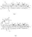
- Fig. 1 is a diagrammatic side section view of the distal end of an ablation catheter embodying employing a thermal monitoring circuit in accordance with the present invention.
- Fig. 2 is a diagrammatic side section view of the distal end of an ablation catheter with an alternate configuration for the thermal monitoring circuit.
- Fig. 3 is a schematic circuit diagram of a thermocouple.
-
- Referring to Fig. 1, an embodiment of the present invention is comprised of an
elongated catheter body 10, a plurality ofelectrodes 11 carried on the distal end of the elongated catheter body, and athermal monitoring circuit 12 comprised of a plurality of thermocouples connected in series. In order to minimize the number of wires needed to monitor the temperature of the electrodes11, thethermal monitoring circuit 12 is comprised of a plurality of thermocouples joined in series. The thermal monitoring circuit will require essentially only two wires in order to monitor a plurality of electrodes. In contrast, the prior art would typically require two wires to travel to and from each electrode. - Referring to Fig. 2, the plurality of
electrodes 11 are preferably coupled to anRF generator 31 by a single RF lead (not shown). TheRF generator 31 is preferably capable of delivering RF energy to each electrode independently and synchronously. Thepreferred RF generator 31 also has a processing means connected in circuit to thethermal monitoring circuit 12 and avisual display 32 for displaying electrode temperature. The processing means calculates the temperature from the voltages at aterminal 23. Theterminal 23 is preferably connected to the processing means 31 through the use of a T-type connector, but it is understood that a variety of different connecting means can be utilized to connect theterminal 23 to the processing means 31. - For purposes of illustration, the thermocouples shown in Figures 1, 2, and 3 are comprised of alternating lengths of copper (CU) and constantan (CO) wire, and the wire segments comprising these materials are labeled as such. However, thermocouples can be made from a variety of metal pairs and is not necessarily limited to copper and constantan. It should be understood that thermocouples employing a metal pair other than copper and constantan can be used with the present invention.
- Referring to Fig. 3, a thermocouple 20 operates on the thermoelectric principle that when two dissimilar metals are joined together, an electrical voltage is generated which is proportional to the metal composition and junction temperature (Seebeck effect). A thermocouple 20 is typically comprised of a sensing junction.21 and a
reference junction 22 and aterminal 23. Thereference junction 22 and thesensing junction 21 will produce DC voltages having opposite polarities and in proportion to the temperature at each junction. Consequently, if there is a difference in temperature between the sensing junction and the reference junction, a DC voltage will be produced at theterminal 23. If there is no difference in temperature between thesensing junction 21 and thereference junction 22, the voltages from the reference junction and the sensing junction will cancel each other out and there will be no voltage across theterminal 23. Referring to Figures 1 and 2, a plurality of thermocouples 20 connected in series will generate a voltage at theterminal 23 equal to the sum of the voltages generated by each thermocouple. - Referring to Figure 1, in this embodiment of the
thermal monitoring circuit 12, the thermocouples are connected in series with thesensing junction 21 and thereference junction 22 of each thermocouple 20 thermoconductively coupled todifferent electrodes 11, preferably attached thereto. Once the elongated catheter body is inserted into the body, both the reference junctions and the sensing junctions are kept at relatively the same temperature, namely body temperature. Once anelectrode 11 is activated, the heat from the electrode will cause thereference 22 or sensing junction 20 thermoconductively coupled to the activated electrode to generate a voltage, either positive or negative. If only one electrode is activated, the voltage at the terminal 23 is generated by the activated electrode. The absolute value of this voltage is reflective of the temperature at the activated electrode, and a temperature for the activated electrode can be calculated therefrom. - Referring to Fig. 2, in an alternative embodiment of the
thermal monitoring circuit 12 50% of the thermocouple junctions will be attached to anelectrode 11 while the other 50% will be thermally isolated from the electrode11. This can be achieved by thermoconductively coupling thesensing junctions 21 to theelectrodes 11 and thermally isolating thereference junctions 22 from theelectrodes 11. In this configuration, a baseline voltage will be generated at the terminal 23 due to body heat. If only oneelectrode 11 is activated, an additional voltage at the terminal 23 is generated by the activated electrode, and a temperature for the activated electrode can be calculated therefrom. If all the electrodes are activated in unison, an additional voltage attributable to the activatedelectrodes 11 is generated at the terminal 23. An average temperature for each electrode can be calculated therefrom by dividing the additional voltage by the number of electrodes and calculating the average electrode temperature therefrom. - One way of thermally isolating the
reference junctions 22 from the electrodes is by disposing the reference junctions in acentral lumen 30 in theelongated catheter body 10. By disposing the reference junctions in thecentral lumen 30, thereference junctions 22 can be placed in the path of the irrigation flow which runs through the catheter. The irrigation flow can provide a relatively stable reference temperature. Thereference junctions 22 can also be thermally isolated from theelectrodes 11, by thermally sealing and insulating thereference junction 22 from the catheter environment. - It can be seen that the ablation catheter which has been provided above allows for improved temperature monitoring while minimizing the space required for such monitoring. Although illustrative embodiments of the invention have been shown and described, it is not intended that the novel device be limited thereby. It is to be understood that this novel invention may be susceptible to modifications and variations that are within the scope and fair meaning of the accompanying claims and drawings.
Claims (10)
- A catheter comprising:an elongated catheter body having proximal and distal ends;a plurality of electrodes mounted on said distal end of said catheter body; anda thermal monitoring circuit, said thermal monitoring circuit comprising a plurality of thermocouples conductively connected in series, said thermocouples being located at said distal end of said elongated catheter body.
- The catheter of claim 1 wherein said thermocouples are thermoconductively coupled to said electrodes.
- The catheter of claim 1 or claim 2 wherein said thermocouples are each comprised of a sensing junction thermoconductively coupled to an electrode and a reference junction which is thermally insulated from said electrode.
- The catheter of any one of claims 1 to 3 wherein said elongated catheter body has a central lumen extending therethrough, and wherein said thermocouples are each comprised of a sensing junction thermoconductively coupled to an electrode and a reference junction positioned within said central lumen.
- The catheter of claim 1 or claim 2 wherein said thermocouples are each comprised of a sensing junction and a reference junction with each sensing junction and reference junction thermoconductively coupled to a separate electrode.
- The catheter of any one of claims 1 to 5 wherein said thermocouples are each comprised of two junctions and wherein 50% of the total junctions are thermoconductively coupled to electrodes and the other 50% of total junctions are thermally isolated.
- The catheter of claim 1 or claim 2 wherein said thermocouples are each comprised of a sensing junction thermoconductively coupled to an electrode and a sealed and insulated reference junction
- The catheter of any one of claims 1 to 7 wherein a single pair of lead wires extend from said thermal monitoring circuit to said proximal end of said elongated catheter body.
- The catheter of any one of claims 1 to 8 wherein said thermocouple is comprised of copper and constantan.
- An ablation catheter comprising:a elongated catheter body having proximal and distal ends;a plurality of electrodes mounted on the distal end of the catheter body, each electrode having a separate electrode wire attached thereto providing a means for selectively delivering RF energy to each individual electrode; anda thermal monitoring circuit, the thermal monitoring circuit comprising a plurality of thermocouples conductively connected in series and located at said distal end of said elongated catheter body, a single pair of lead wires extending from said thermal monitoring circuit to said proximal end of said elongated catheter body.
Applications Claiming Priority (2)
| Application Number | Priority Date | Filing Date | Title |
|---|---|---|---|
| US614362 | 2000-07-12 | ||
| US09/614,362 US6425894B1 (en) | 2000-07-12 | 2000-07-12 | Ablation catheter with electrode temperature monitoring |
Publications (2)
| Publication Number | Publication Date |
|---|---|
| EP1172070A1 true EP1172070A1 (en) | 2002-01-16 |
| EP1172070B1 EP1172070B1 (en) | 2004-11-24 |
Family
ID=24460931
Family Applications (1)
| Application Number | Title | Priority Date | Filing Date |
|---|---|---|---|
| EP01305876A Expired - Lifetime EP1172070B1 (en) | 2000-07-12 | 2001-07-06 | Ablation catheter with electrode temperature monitoring |
Country Status (3)
| Country | Link |
|---|---|
| US (1) | US6425894B1 (en) |
| EP (1) | EP1172070B1 (en) |
| DE (1) | DE60107329T2 (en) |
Cited By (1)
| Publication number | Priority date | Publication date | Assignee | Title |
|---|---|---|---|---|
| WO2011003432A1 (en) * | 2009-07-10 | 2011-01-13 | Stockert Ruediger | Temperature sensor for measurement on or in a living body |
Families Citing this family (37)
| Publication number | Priority date | Publication date | Assignee | Title |
|---|---|---|---|---|
| ATE507788T1 (en) * | 1998-12-18 | 2011-05-15 | Celon Ag Medical Instruments | ELECTRODE ARRANGEMENT FOR A SURGICAL INSTRUMENT FOR ELECTROTHERMAL COAGULATION IN TISSUE |
| AU2001249874A1 (en) | 2000-04-27 | 2001-11-12 | Medtronic, Inc. | System and method for assessing transmurality of ablation lesions |
| US6669692B1 (en) | 2000-08-21 | 2003-12-30 | Biosense Webster, Inc. | Ablation catheter with cooled linear electrode |
| US20060089637A1 (en) * | 2004-10-14 | 2006-04-27 | Werneth Randell L | Ablation catheter |
| US8617152B2 (en) | 2004-11-15 | 2013-12-31 | Medtronic Ablation Frontiers Llc | Ablation system with feedback |
| US7468062B2 (en) | 2004-11-24 | 2008-12-23 | Ablation Frontiers, Inc. | Atrial ablation catheter adapted for treatment of septal wall arrhythmogenic foci and method of use |
| US7429261B2 (en) | 2004-11-24 | 2008-09-30 | Ablation Frontiers, Inc. | Atrial ablation catheter and method of use |
| US8182433B2 (en) * | 2005-03-04 | 2012-05-22 | Endosense Sa | Medical apparatus system having optical fiber load sensing capability |
| US8075498B2 (en) | 2005-03-04 | 2011-12-13 | Endosense Sa | Medical apparatus system having optical fiber load sensing capability |
| US7857810B2 (en) * | 2006-05-16 | 2010-12-28 | St. Jude Medical, Atrial Fibrillation Division, Inc. | Ablation electrode assembly and methods for improved control of temperature and minimization of coagulation and tissue damage |
| US20080091193A1 (en) * | 2005-05-16 | 2008-04-17 | James Kauphusman | Irrigated ablation catheter having magnetic tip for magnetic field control and guidance |
| US8128621B2 (en) | 2005-05-16 | 2012-03-06 | St. Jude Medical, Atrial Fibrillation Division, Inc. | Irrigated ablation electrode assembly and method for control of temperature |
| EP1895927A4 (en) | 2005-06-20 | 2011-03-09 | Medtronic Ablation Frontiers | Ablation catheter |
| CA2615267A1 (en) | 2005-07-11 | 2007-01-18 | Ablation Frontiers, Inc. | Low power tissue ablation system |
| EP3028645B1 (en) | 2005-08-01 | 2019-09-18 | St. Jude Medical International Holding S.à r.l. | Medical apparatus system having optical fiber load sensing capability |
| US8657814B2 (en) * | 2005-08-22 | 2014-02-25 | Medtronic Ablation Frontiers Llc | User interface for tissue ablation system |
| US8567265B2 (en) | 2006-06-09 | 2013-10-29 | Endosense, SA | Triaxial fiber optic force sensing catheter |
| US8048063B2 (en) | 2006-06-09 | 2011-11-01 | Endosense Sa | Catheter having tri-axial force sensor |
| US8641704B2 (en) | 2007-05-11 | 2014-02-04 | Medtronic Ablation Frontiers Llc | Ablation therapy system and method for treating continuous atrial fibrillation |
| US8157789B2 (en) * | 2007-05-24 | 2012-04-17 | Endosense Sa | Touch sensing catheter |
| US8622935B1 (en) | 2007-05-25 | 2014-01-07 | Endosense Sa | Elongated surgical manipulator with body position and distal force sensing |
| US8052684B2 (en) * | 2007-11-30 | 2011-11-08 | St. Jude Medical, Atrial Fibrillation Division, Inc. | Irrigated ablation catheter having parallel external flow and proximally tapered electrode |
| CN101888813B (en) * | 2007-12-06 | 2012-12-12 | 皇家飞利浦电子股份有限公司 | Apparatus, a method and a computer program for applying energy to an object |
| US8298227B2 (en) * | 2008-05-14 | 2012-10-30 | Endosense Sa | Temperature compensated strain sensing catheter |
| US8668686B2 (en) * | 2009-12-23 | 2014-03-11 | Biosense Webster (Israel) Ltd. | Sensing contact of ablation catheter using differential temperature measurements |
| US8641708B2 (en) * | 2009-12-29 | 2014-02-04 | Biosense Webster (Israel), Ltd. | Measuring weak signals over ablation lines |
| WO2012068505A1 (en) * | 2010-11-19 | 2012-05-24 | St. Jude Medical, Atrial Fibrillation Division, Inc. | Electrode catheter device with indifferent electrode for direct current tissue therapies |
| CN103607961B (en) | 2011-04-14 | 2016-12-14 | 圣犹达医疗用品卢森堡控股有限公司 | Compact force sensor for conduit |
| US9743975B2 (en) | 2012-10-02 | 2017-08-29 | Covidien Lp | Thermal ablation probe for a medical device |
| US20140276562A1 (en) * | 2013-03-14 | 2014-09-18 | Biosense Webster (Israel), Ltd. | Catheter with spray irrigation |
| US20150342671A1 (en) * | 2014-05-29 | 2015-12-03 | Biosense Webster (Israel) Ltd. | Catheter electrode with multiple thermocouples |
| WO2016161209A1 (en) | 2015-03-31 | 2016-10-06 | St. Jude Medical, Cardiology Division, Inc. | Methods and devices for delivering pulsed rf energy during catheter ablation |
| US10285751B2 (en) | 2015-10-16 | 2019-05-14 | Biosense Webster (Israel) Ltd. | System and method for controlling catheter power based on renal ablation response |
| US11445937B2 (en) | 2016-01-07 | 2022-09-20 | St. Jude Medical International Holding S.À R.L. | Medical device with multi-core fiber for optical sensing |
| US11246658B2 (en) | 2016-10-04 | 2022-02-15 | St. Jude Medical, Cardiology Division, Inc. | Ablation catheter tip |
| CN109620398B (en) * | 2019-02-01 | 2024-02-09 | 科塞尔医疗科技(苏州)有限公司 | Ablation electrode and catheter matched with same |
| US12150702B1 (en) | 2024-06-03 | 2024-11-26 | Physcade, Inc. | Generator and catheter for tissue ablation |
Citations (3)
| Publication number | Priority date | Publication date | Assignee | Title |
|---|---|---|---|---|
| WO1996000036A1 (en) * | 1994-06-27 | 1996-01-04 | Ep Technologies, Inc. | System for controlling tissue ablation using temperature sensors |
| DE29681114U1 (en) * | 1995-12-14 | 1997-10-30 | Muntermann, Axel, 35583 Wetzlar | Device for linear high-frequency catheter ablation of endomyocardial tissue |
| US6049737A (en) * | 1998-05-05 | 2000-04-11 | Cardiac Pacemakers, Inc. | Catheter having common lead for electrode and sensor |
Family Cites Families (7)
| Publication number | Priority date | Publication date | Assignee | Title |
|---|---|---|---|---|
| US4411266A (en) * | 1980-09-24 | 1983-10-25 | Cosman Eric R | Thermocouple radio frequency lesion electrode |
| AU1152592A (en) * | 1990-12-12 | 1992-07-08 | Sherwood Ims, Inc. | Infrared thermometer utilizing calibration mapping |
| JP3578460B2 (en) * | 1994-06-27 | 2004-10-20 | ボストン サイエンティフィック リミテッド | Systems and methods for sensing body temperature |
| US5837001A (en) * | 1995-12-08 | 1998-11-17 | C. R. Bard | Radio frequency energy delivery system for multipolar electrode catheters |
| US5755760A (en) * | 1996-03-11 | 1998-05-26 | Medtronic, Inc. | Deflectable catheter |
| US6050994A (en) * | 1998-05-05 | 2000-04-18 | Cardiac Pacemakers, Inc. | RF ablation apparatus and method using controllable duty cycle with alternate phasing |
| US6245065B1 (en) * | 1998-09-10 | 2001-06-12 | Scimed Life Systems, Inc. | Systems and methods for controlling power in an electrosurgical probe |
-
2000
- 2000-07-12 US US09/614,362 patent/US6425894B1/en not_active Expired - Lifetime
-
2001
- 2001-07-06 DE DE60107329T patent/DE60107329T2/en not_active Expired - Lifetime
- 2001-07-06 EP EP01305876A patent/EP1172070B1/en not_active Expired - Lifetime
Patent Citations (3)
| Publication number | Priority date | Publication date | Assignee | Title |
|---|---|---|---|---|
| WO1996000036A1 (en) * | 1994-06-27 | 1996-01-04 | Ep Technologies, Inc. | System for controlling tissue ablation using temperature sensors |
| DE29681114U1 (en) * | 1995-12-14 | 1997-10-30 | Muntermann, Axel, 35583 Wetzlar | Device for linear high-frequency catheter ablation of endomyocardial tissue |
| US6049737A (en) * | 1998-05-05 | 2000-04-11 | Cardiac Pacemakers, Inc. | Catheter having common lead for electrode and sensor |
Cited By (3)
| Publication number | Priority date | Publication date | Assignee | Title |
|---|---|---|---|---|
| WO2011003432A1 (en) * | 2009-07-10 | 2011-01-13 | Stockert Ruediger | Temperature sensor for measurement on or in a living body |
| JP2012531982A (en) * | 2009-07-10 | 2012-12-13 | ルーディゲル シュトッケルト | Temperature sensor for measuring on or inside a living body |
| US9103730B2 (en) | 2009-07-10 | 2015-08-11 | Ruediger Stockert | Temperature sensor for measurement on or in a living body |
Also Published As
| Publication number | Publication date |
|---|---|
| DE60107329T2 (en) | 2005-12-08 |
| DE60107329D1 (en) | 2004-12-30 |
| US6425894B1 (en) | 2002-07-30 |
| EP1172070B1 (en) | 2004-11-24 |
Similar Documents
| Publication | Publication Date | Title |
|---|---|---|
| EP1172070B1 (en) | Ablation catheter with electrode temperature monitoring | |
| US6451011B2 (en) | Medical device having temperature sensing and ablation capabilities | |
| US11684416B2 (en) | Insulated ablation catheter devices and methods of use | |
| EP0783265B1 (en) | Apparatus for procedures related to the electrophysiology of the heart | |
| US5967976A (en) | Apparatus and methods for procedures related to the electrophysiology of the heart | |
| US6176857B1 (en) | Method and apparatus for applying thermal energy to tissue asymmetrically | |
| US5893885A (en) | Multi-electrode ablation catheter | |
| US10918437B2 (en) | Catheter with coaxial thermocouple | |
| JP7350475B2 (en) | Catheter with improved temperature response | |
| EP3416579B1 (en) | Multiple thermocouple assembly with reduced wire count | |
| EP3932354B1 (en) | Electroporation with cooling | |
| AU2019403083B2 (en) | Cooled radiofrequency ablation probe | |
| US12245806B2 (en) | Cooled bipolar radio-frequency ablation probe | |
| JPH0228985B2 (en) |
Legal Events
| Date | Code | Title | Description |
|---|---|---|---|
| PUAI | Public reference made under article 153(3) epc to a published international application that has entered the european phase |
Free format text: ORIGINAL CODE: 0009012 |
|
| AK | Designated contracting states |
Kind code of ref document: A1 Designated state(s): AT BE CH CY DE DK ES FI FR GB GR IE IT LI LU MC NL PT SE TR Kind code of ref document: A1 Designated state(s): DE NL |
|
| AX | Request for extension of the european patent |
Free format text: AL;LT;LV;MK;RO;SI |
|
| 17P | Request for examination filed |
Effective date: 20020624 |
|
| AKX | Designation fees paid |
Free format text: DE NL |
|
| GRAP | Despatch of communication of intention to grant a patent |
Free format text: ORIGINAL CODE: EPIDOSNIGR1 |
|
| GRAS | Grant fee paid |
Free format text: ORIGINAL CODE: EPIDOSNIGR3 |
|
| GRAA | (expected) grant |
Free format text: ORIGINAL CODE: 0009210 |
|
| AK | Designated contracting states |
Kind code of ref document: B1 Designated state(s): DE NL |
|
| REF | Corresponds to: |
Ref document number: 60107329 Country of ref document: DE Date of ref document: 20041230 Kind code of ref document: P |
|
| REG | Reference to a national code |
Ref country code: IE Ref legal event code: FG4D |
|
| PLBE | No opposition filed within time limit |
Free format text: ORIGINAL CODE: 0009261 |
|
| STAA | Information on the status of an ep patent application or granted ep patent |
Free format text: STATUS: NO OPPOSITION FILED WITHIN TIME LIMIT |
|
| 26N | No opposition filed |
Effective date: 20050825 |
|
| PGFP | Annual fee paid to national office [announced via postgrant information from national office to epo] |
Ref country code: NL Payment date: 20200715 Year of fee payment: 20 |
|
| PGFP | Annual fee paid to national office [announced via postgrant information from national office to epo] |
Ref country code: DE Payment date: 20200624 Year of fee payment: 20 |
|
| REG | Reference to a national code |
Ref country code: DE Ref legal event code: R071 Ref document number: 60107329 Country of ref document: DE |
|
| REG | Reference to a national code |
Ref country code: NL Ref legal event code: MK Effective date: 20210705 |