EP1172032A1 - A construction for automatically milking animals - Google Patents
A construction for automatically milking animals Download PDFInfo
- Publication number
- EP1172032A1 EP1172032A1 EP01202235A EP01202235A EP1172032A1 EP 1172032 A1 EP1172032 A1 EP 1172032A1 EP 01202235 A EP01202235 A EP 01202235A EP 01202235 A EP01202235 A EP 01202235A EP 1172032 A1 EP1172032 A1 EP 1172032A1
- Authority
- EP
- European Patent Office
- Prior art keywords
- construction
- robot arm
- milk box
- rail
- teat cups
- Prior art date
- Legal status (The legal status is an assumption and is not a legal conclusion. Google has not performed a legal analysis and makes no representation as to the accuracy of the status listed.)
- Granted
Links
Images


Classifications
-
- A—HUMAN NECESSITIES
- A01—AGRICULTURE; FORESTRY; ANIMAL HUSBANDRY; HUNTING; TRAPPING; FISHING
- A01J—MANUFACTURE OF DAIRY PRODUCTS
- A01J5/00—Milking machines or devices
- A01J5/017—Automatic attaching or detaching of clusters
- A01J5/0175—Attaching of clusters
Definitions
- the invention relates to a construction for automatically milking animals according to the preamble of claim 1.
- the invention aims at improving such a construction. According to the invention this is achieved by the measures described in the characterizing part of claim 1.
- the control of the robot arm is relatively simple and yet reliable and accurate.
- FIG. 1 is a schematic side view of a construction according to the invention.
- the construction for automatically milking animals comprises a milk box 1 with a milking robot 2, known per se, which is provided with a controllable robot arm 3 for connecting teat cups 4 to the teats of an animal 5 to be milked (indicated by a dotted line).
- the robot arm 3 is suspended from a ball joint 7 which is controllable by means of two control elements, such as e.g. cylinders 9, via an intermediate element 8 connected therewith.
- the long, substantially vertical part of the robot arm 3 is movable in two directions by means of the two control cylinders 9.
- the ball joint 7 is shiftably fastened to the milk box 1 (in the embodiment shown in horizontal direction).
- a further part of the robot arm 3 is provided with a carrier element 10 for the teat cups 4.
- said carrier element 10 is movable substantially in vertical direction relative to the straight part of the robot arm 3 that is connected with the ball joint 7.
- the further control means comprise a parallelogram construction 11.
- the further control means may also be designed differently, such as e.g. a telescope construction, a cylinder construction or a hingeable construction.
- the ball joint 7 is again shiftably fastened to the milk box 1.
- the robot arm 3 is now connected with an intermediate element 12 which is itself connected with the two control cylinders 9.
- the cylinders 9 are also shiftably fastened to the milk box 1.
- the robot arm 3 can in principle be moved in the same manner.
- the ball joint 7 is again shiftably fastened to the milk box 1.
- the robot arm 3 is now vertically movable by means of a telescope construction and again connected with an intermediate element 12 which is itself connected with the two control cylinders 9.
- the cylinders 9 are also shiftably fastened to the milk box 1.
- the robot arm 3 can in principle again be moved in the same manner.
- the ball joint 7 is fastened at a rather low level at the lateral side just outside the milk box 1.
- the ball joint 7 is again shiftable in the longitudinal direction of the milk box 1.
- the carrier element 10 with the teat cups 4 is provided with an air-cushion construction 13 and is thus suitable for being moved in a floating manner over the floor of the milk box 1.
- the robot arm 3 can be pivoted to under the udder of the animal 5 to be milked and again be pivoted away therefrom.
- the carrier element 10 is further provided with a rod construction 14 with controllable hinges by means of which the teat cups 4 can be moved in vertical direction. Said robot arm construction is very compact.
- Figures 9 and 10 show schematically a part of a further construction (without ball joint) for automatically milking animals.
- the construction is provided with a milk box 15 with a milking robot 16 (known per se), which is provided with a controllable robot arm 17 for connecting teat cups 18 to the teats of a (non-shown) animal to be milked.
- the robot arm 17 is suspended from a suspension element 20 that is movable along a rail construction 19 which extends preferably in the longitudinal direction of the milk box 15.
- the rail construction 19 is partially pivotably connected with the milk box 15 and comprises a first round rail 21, which is fixedly connected to the milk box 15, and a second round rail 22 extending parallel to the first rail 21, said second round rail 22 being pivotable by means of a control element 23 that is connected to the milk box 15 (see Figure 10).
- the construction is suitable for moving the teat cups 18 to under the animal to be milked or away therefrom by means of the pivoting movement of the rail construction 19.
- the teat cups 18 can be moved in vertical direction.
- the pivotable rail construction 19 with the double suspension element 20, bearing on two rails 21, 22, is very robust.
- FIG 11 is a schematic view of a part of a further construction (without ball joint) for automatically milking animals.
- the construction is provided with a milk box 24 with a milking robot 25 (known per se), which is provided with a controllable robot arm 26 for connecting teat cups 27 to the teats of a (non-shown) animal to be milked.
- the robot arm 26 is rotatably suspended about a substantially vertical axis 28 and is suitable for moving the teat cups 27 to under the animal to be milked or away therefrom by means of the rotation about the substantially vertical axis.
- the lower part of the robot arm 26 is provided with a portion which extends substantially horizontally, perpendicularly to the longitudinal direction of the milk box 24 (i.e. perpendicularly to the plane of drawing of Figure 11) and which can reach to under the udder of the animal to be milked.
- the rotation takes place by means of a control cylinder 29.
- the teat cups 27 can be moved in the longitudinal direction of the milk box 24 with the aid of (for example) a telescope construction and in vertical direction with the aid of a further telescope construction or for example a parallelogram construction.
- Said robot arm construction is compact and occupies relatively few space during the pivoting movement.
Abstract
Description
- The invention relates to a construction for automatically milking animals according to the preamble of claim 1.
- Such a construction is known. With the known constructions the controllable robot arm is often pivotably suspended about an axis. This has inter alia the disadvantage that for realizing the necessary three-dimensional movements there is required a complex control for the robot arm.
- The invention aims at improving such a construction. According to the invention this is achieved by the measures described in the characterizing part of claim 1. By means of the suspension from the ball joint the control of the robot arm is relatively simple and yet reliable and accurate.
- The invention will now be explained in further detail with reference to the accompanying figures.
- Figure 1 is a schematic side view of a construction according to the invention;
- Figure 2 is a schematic view of a part of the construction according to the arrows II in Figure 1;
- Figure 3 is a schematic view of a part of the construction according to the arrow III in Figure 2;
- Figure 4 is a schematic view of a part of the construction in a further embodiment;
- Figure 5 is a schematic view of a part of the construction in a still further embodiment;
- Figure 6 is a schematic view of a part of the construction in another further embodiment;
- Figure 7 is a schematic view of a part of the construction according to the arrow VII in Figure 6;
- Figure 8 is a schematic cross-section of a part of the construction according to the arrow VIII in Figure 7;
- Figure 9 is a schematic side view of a part of a further construction;
- Figure 10 is a schematic view of a part of the construction according to the arrow X in Figure 9, and
- Figure 11 is a schematic view of a part of a further construction.
-
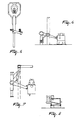
- Figure 1 is a schematic side view of a construction according to the invention. The construction for automatically milking animals comprises a milk box 1 with a milking robot 2, known per se, which is provided with a controllable robot arm 3 for connecting teat cups 4 to the teats of an animal 5 to be milked (indicated by a dotted line). During automatic milking the animal 5 can eat and/or drink from a feeding trough 6. The robot arm 3 is suspended from a ball joint 7 which is controllable by means of two control elements, such as e.g. cylinders 9, via an intermediate element 8 connected therewith. The long, substantially vertical part of the robot arm 3 is movable in two directions by means of the two control cylinders 9.
- As also illustrated in Figures 2 and 3, the ball joint 7 is shiftably fastened to the milk box 1 (in the embodiment shown in horizontal direction). A further part of the robot arm 3 is provided with a carrier element 10 for the teat cups 4. With the aid of further control means, said carrier element 10 is movable substantially in vertical direction relative to the straight part of the robot arm 3 that is connected with the ball joint 7. In the embodiment shown in Figures 1 to 3, the further control means comprise a parallelogram construction 11. Of course, the further control means may also be designed differently, such as e.g. a telescope construction, a cylinder construction or a hingeable construction.
- In the embodiment of Figure 4 the ball joint 7 is again shiftably fastened to the milk box 1. The robot arm 3 is now connected with an intermediate element 12 which is itself connected with the two control cylinders 9. The cylinders 9 are also shiftably fastened to the milk box 1. The robot arm 3 can in principle be moved in the same manner.
- In the embodiment of Figure 5 the ball joint 7 is again shiftably fastened to the milk box 1. The robot arm 3 is now vertically movable by means of a telescope construction and again connected with an intermediate element 12 which is itself connected with the two control cylinders 9. The cylinders 9 are also shiftably fastened to the milk box 1. The robot arm 3 can in principle again be moved in the same manner.
- In the embodiment of Figures 6 to 8 the ball joint 7 is fastened at a rather low level at the lateral side just outside the milk box 1. The ball joint 7 is again shiftable in the longitudinal direction of the milk box 1. The carrier element 10 with the teat cups 4 is provided with an air-cushion construction 13 and is thus suitable for being moved in a floating manner over the floor of the milk box 1. With the aid of the cylinder 9 the robot arm 3 can be pivoted to under the udder of the animal 5 to be milked and again be pivoted away therefrom. As shown in Figure 8, the carrier element 10 is further provided with a rod construction 14 with controllable hinges by means of which the teat cups 4 can be moved in vertical direction. Said robot arm construction is very compact.
- Figures 9 and 10 show schematically a part of a further construction (without ball joint) for automatically milking animals. The construction is provided with a
milk box 15 with a milking robot 16 (known per se), which is provided with a controllable robot arm 17 for connecting teat cups 18 to the teats of a (non-shown) animal to be milked. The robot arm 17 is suspended from asuspension element 20 that is movable along a rail construction 19 which extends preferably in the longitudinal direction of themilk box 15. The rail construction 19 is partially pivotably connected with themilk box 15 and comprises afirst round rail 21, which is fixedly connected to themilk box 15, and asecond round rail 22 extending parallel to thefirst rail 21, saidsecond round rail 22 being pivotable by means of a control element 23 that is connected to the milk box 15 (see Figure 10). - The construction is suitable for moving the teat cups 18 to under the animal to be milked or away therefrom by means of the pivoting movement of the rail construction 19. By means of (for example) a parallelogram construction the teat cups 18 can be moved in vertical direction. The pivotable rail construction 19 with the
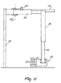
double suspension element 20, bearing on tworails - Figure 11 is a schematic view of a part of a further construction (without ball joint) for automatically milking animals. The construction is provided with a
milk box 24 with a milking robot 25 (known per se), which is provided with acontrollable robot arm 26 for connectingteat cups 27 to the teats of a (non-shown) animal to be milked. Therobot arm 26 is rotatably suspended about a substantially vertical axis 28 and is suitable for moving theteat cups 27 to under the animal to be milked or away therefrom by means of the rotation about the substantially vertical axis. For that purpose the lower part of therobot arm 26 is provided with a portion which extends substantially horizontally, perpendicularly to the longitudinal direction of the milk box 24 (i.e. perpendicularly to the plane of drawing of Figure 11) and which can reach to under the udder of the animal to be milked. - The rotation takes place by means of a
control cylinder 29. Theteat cups 27 can be moved in the longitudinal direction of themilk box 24 with the aid of (for example) a telescope construction and in vertical direction with the aid of a further telescope construction or for example a parallelogram construction. Said robot arm construction is compact and occupies relatively few space during the pivoting movement.
Claims (15)
- A construction for automatically milking animals, said construction comprising a milk box (1) with a milking robot (2), which is provided with a controllable robot arm (3) for connecting teat cups (4) to the teats of an animal (5) to be milked, characterized in that the robot arm (3) is suspended from a ball joint (7).
- A construction as claimed in claim 1, characterized in that the robot arm (3) and/or the ball joint (7) connected therewith are/is controllable by means of at least one control element (9).
- A construction as claimed in claim 1 or 2, characterized in that a part of the robot arm (3) and/or the ball joint (7) connected therewith are/is connected with two control cylinders (9) in such a manner that said part of the robot arm (3) is movable substantially in two directions.
- A construction as claimed in any one of claims 1 to 3, characterized in that the ball joint (7) is shiftably fastened to the milk box (1).
- A construction as claimed in claim 3 or 4, characterized in that a further part of the robot arm (3) is provided with a carrier element (10) for the teat cups (4), at least the carrier element (10) being movable with the aid of further control means (11) substantially in one direction relative to the part that is connected with the ball joint (7).
- A construction as claimed in claim 5, characterized in that the further control means comprise a parallelogram construction (11).
- A construction as claimed in claim 5 or 6, characterized in that the further control means comprise a telescope construction.
- A construction as claimed in any one of claims 5 to 7, characterized in that the further control means comprise a cylinder construction.
- A construction as claimed in any one of claims 5 to 8, characterized in that the further control means comprise a hingeable construction.
- A construction as claimed in any one of claims 5 to 9, characterized in that the further part of the robot arm (3) with the teat cups (4) is provided with an air-cushion construction (13) and is suitable for being moved in a floating manner over the floor of the milk box (1).
- A construction for automatically milking animals, said construction comprising a milk box (15) with a milking robot (16), which is provided with a controllable robot arm (17) for connecting teat cups (18) to the teats of an animal to be milked, characterized in that the robot arm (17) is suspended from a suspension element (20) that is movable along a rail construction (19), said rail construction (19) being at least partially pivotably connected with the milk box (15).
- A construction as claimed in claim 11, characterized in that the rail construction (19) comprises a first rail (21), which is fixedly fastened to the milk box (15), and a second rail (22) extending parallel to the first rail (21), said second rail (22) being pivotable by means of a control element (23) that is connected with the milk box (15).
- A construction as claimed in any one of claims 11 and 12, characterized in that the construction is suitable for moving the teat cups (18) to under the animal to be milked or away from said animal by means of the pivoting movement of the rail construction (19).
- A construction for automatically milking animals, said construction comprising a milk box (24) with a milking robot (25), which is provided with a controllable robot arm (26) for connecting teat cups (27) to the teats of an animal to be milked, characterized in that the robot arm (26) is suspended rotatably about a substantially vertical axis (28).
- A construction as claimed in claim 14, characterized in that the robot arm (26) is suitable for moving the teat cups (27) to under the animal to be milked or away therefrom by means of the rotation about the substantially vertical axis (28).
Applications Claiming Priority (2)
| Application Number | Priority Date | Filing Date | Title |
|---|---|---|---|
| NL1015670 | 2000-07-10 | ||
| NL1015670A NL1015670C2 (en) | 2000-07-10 | 2000-07-10 | Device for automatic milking of animals. |
Publications (3)
| Publication Number | Publication Date |
|---|---|
| EP1172032A1 true EP1172032A1 (en) | 2002-01-16 |
| EP1172032B1 EP1172032B1 (en) | 2004-09-22 |
| EP1172032B2 EP1172032B2 (en) | 2008-07-16 |
Family
ID=19771707
Family Applications (1)
| Application Number | Title | Priority Date | Filing Date |
|---|---|---|---|
| EP01202235A Expired - Lifetime EP1172032B2 (en) | 2000-07-10 | 2001-06-11 | A construction for automatically milking animals |
Country Status (7)
| Country | Link |
|---|---|
| US (1) | US6584929B2 (en) |
| EP (1) | EP1172032B2 (en) |
| JP (1) | JP2002034369A (en) |
| AT (1) | ATE276649T1 (en) |
| AU (1) | AU5392601A (en) |
| DE (1) | DE60105709T3 (en) |
| NL (1) | NL1015670C2 (en) |
Cited By (1)
| Publication number | Priority date | Publication date | Assignee | Title |
|---|---|---|---|---|
| NL1035763C2 (en) * | 2008-07-28 | 2010-01-29 | Lely Patent Nv | Automatic milking installation. |
Families Citing this family (7)
| Publication number | Priority date | Publication date | Assignee | Title |
|---|---|---|---|---|
| NL1016023C2 (en) * | 2000-08-25 | 2002-02-26 | Idento Electronics Bv | Milking device and holder for receiving teat cups. |
| DE102011001404A1 (en) | 2011-03-18 | 2012-09-20 | Gea Farm Technologies Gmbh | Milking parlor and milking parlor with such a milking parlor |
| RU2556039C2 (en) | 2011-03-18 | 2015-07-10 | Геа Фарм Текнолоджиз Гмбх | Milking unit and milking machine provided with such milking unit |
| DE102012102133A1 (en) * | 2012-03-14 | 2013-09-19 | Gea Farm Technologies Gmbh | MELSTAND ASSEMBLY WITH AN INNER ROBOT DEVICE |
| DE102012110501A1 (en) * | 2012-03-14 | 2013-09-19 | Gea Farm Technologies Gmbh | Divider of a milking parlor arrangement and milking parlor arrangement |
| DE102014107124A1 (en) | 2014-05-20 | 2015-11-26 | Gea Farm Technologies Gmbh | Arm arrangement for a milking parlor arrangement for the automatic milking of dairy animals, divider of a milking parlor arrangement and milking parlor arrangement |
| SE1750686A1 (en) * | 2017-05-31 | 2018-02-21 | Delaval Holding Ab | End effector and arrangement for performing an animal related operation |
Citations (3)
| Publication number | Priority date | Publication date | Assignee | Title |
|---|---|---|---|---|
| FR2595197A1 (en) * | 1986-03-07 | 1987-09-11 | Cemagref | Automatic milking installation |
| WO1998001022A1 (en) * | 1996-07-05 | 1998-01-15 | Maasland N.V. | An implement for automatically milking animals |
| WO1999025177A1 (en) * | 1997-11-14 | 1999-05-27 | Delaval Holding Ab | An apparatus for performing an animal related operation |
Family Cites Families (14)
| Publication number | Priority date | Publication date | Assignee | Title |
|---|---|---|---|---|
| US3789798A (en) * | 1972-08-10 | 1974-02-05 | Sta Rite Industries | Automatic milking unit |
| US3798798A (en) * | 1973-03-30 | 1974-03-26 | F Shore | Frame-selection picture frame simulator |
| US3929103A (en) * | 1974-12-06 | 1975-12-30 | Dec Int | Detacher mechanism for milking unit |
| ATE74254T1 (en) * | 1985-01-16 | 1992-04-15 | Lely Nv C Van Der | EQUIPMENT AND METHOD FOR MILKING ANIMALS SUCH AS COWS. |
| NL8500088A (en) * | 1985-01-16 | 1986-08-18 | Lely Nv C Van Der | DEVICE FOR AUTOMATIC MILKING OF AN ANIMAL. |
| NL193715C (en) * | 1987-07-23 | 2000-08-04 | Lely Nv C Van Der | Device for milking an animal. |
| GB8900084D0 (en) * | 1989-01-04 | 1989-03-01 | British Res Agricult Eng | Milking |
| GB9113405D0 (en) * | 1991-06-20 | 1991-08-07 | Silsoe Research Inst | Automatic milking |
| NL9101673A (en) * | 1991-10-04 | 1993-05-03 | Texas Industries Inc | Apparatus for cleaning teats of milking animals. |
| NL9200091A (en) * | 1992-01-17 | 1993-08-16 | Lely Nv C Van Der | MILK MACHINE. |
| DE69535110T2 (en) * | 1994-03-25 | 2007-02-08 | Maasland N.V. | Plant with at least one device for automatic milking of animals |
| NL1004406C2 (en) * | 1996-08-01 | 1998-02-05 | Maasland Nv | Device for automatic milking of animals. |
| SE9702902D0 (en) * | 1997-08-08 | 1997-08-08 | Alfa Laval Agri Ab | A teatcup supplying and retrieving device and an automatic milking apparatus therefor |
| US6382130B1 (en) * | 1999-11-16 | 2002-05-07 | Tim M. Rooney | Positioner for milking apparatus |
-
2000
- 2000-07-10 NL NL1015670A patent/NL1015670C2/en not_active IP Right Cessation
-
2001
- 2001-06-11 AT AT01202235T patent/ATE276649T1/en not_active IP Right Cessation
- 2001-06-11 DE DE60105709T patent/DE60105709T3/en not_active Expired - Lifetime
- 2001-06-11 EP EP01202235A patent/EP1172032B2/en not_active Expired - Lifetime
- 2001-06-19 AU AU53926/01A patent/AU5392601A/en not_active Abandoned
- 2001-07-02 JP JP2001200465A patent/JP2002034369A/en not_active Withdrawn
- 2001-07-10 US US09/901,067 patent/US6584929B2/en not_active Expired - Fee Related
Patent Citations (3)
| Publication number | Priority date | Publication date | Assignee | Title |
|---|---|---|---|---|
| FR2595197A1 (en) * | 1986-03-07 | 1987-09-11 | Cemagref | Automatic milking installation |
| WO1998001022A1 (en) * | 1996-07-05 | 1998-01-15 | Maasland N.V. | An implement for automatically milking animals |
| WO1999025177A1 (en) * | 1997-11-14 | 1999-05-27 | Delaval Holding Ab | An apparatus for performing an animal related operation |
Cited By (3)
| Publication number | Priority date | Publication date | Assignee | Title |
|---|---|---|---|---|
| NL1035763C2 (en) * | 2008-07-28 | 2010-01-29 | Lely Patent Nv | Automatic milking installation. |
| WO2010014002A1 (en) | 2008-07-28 | 2010-02-04 | Lely Patent N.V. | Automatic milking device |
| US8646410B2 (en) | 2008-07-28 | 2014-02-11 | Lely Patent N.V. | Automatic milking device |
Also Published As
| Publication number | Publication date |
|---|---|
| DE60105709D1 (en) | 2004-10-28 |
| US20020002953A1 (en) | 2002-01-10 |
| ATE276649T1 (en) | 2004-10-15 |
| NL1015670C2 (en) | 2002-01-11 |
| EP1172032B1 (en) | 2004-09-22 |
| EP1172032B2 (en) | 2008-07-16 |
| US6584929B2 (en) | 2003-07-01 |
| DE60105709T3 (en) | 2009-01-02 |
| DE60105709T2 (en) | 2005-10-20 |
| JP2002034369A (en) | 2002-02-05 |
| AU5392601A (en) | 2002-01-17 |
Similar Documents
| Publication | Publication Date | Title |
|---|---|---|
| EP1026943B1 (en) | An apparatus for performing an animal related operation | |
| EP0565189B1 (en) | A construction for automatically milking animals | |
| EP0188303B1 (en) | Implement for automatically milking an animal | |
| EP0726703B1 (en) | An implement for and a method of milking animals | |
| EP0319523B2 (en) | Device for automatically milking an animal | |
| EP0700245B1 (en) | A construction including an implement for milking animals | |
| EP1172032B1 (en) | A construction for automatically milking animals | |
| US7044079B2 (en) | Device for automatically milking an animal | |
| EP0693871B1 (en) | A construction for automatically milking animals | |
| EP1172029B1 (en) | A construction for automatically milking animals | |
| US6481372B2 (en) | Construction for automatically milking animals | |
| EP1172031B1 (en) | A construction for automatically milking animals | |
| EP0617885A1 (en) | A construction for automatically milking animals |
Legal Events
| Date | Code | Title | Description |
|---|---|---|---|
| PUAI | Public reference made under article 153(3) epc to a published international application that has entered the european phase |
Free format text: ORIGINAL CODE: 0009012 |
|
| AK | Designated contracting states |
Kind code of ref document: A1 Designated state(s): AT BE CH CY DE DK ES FI FR GB GR IE IT LI LU MC NL PT SE TR |
|
| AX | Request for extension of the european patent |
Free format text: AL;LT;LV;MK;RO;SI |
|
| 17P | Request for examination filed |
Effective date: 20020528 |
|
| AKX | Designation fees paid |
Free format text: AT BE CH CY DE DK ES FI FR GB GR IE IT LI LU MC NL PT SE TR |
|
| GRAP | Despatch of communication of intention to grant a patent |
Free format text: ORIGINAL CODE: EPIDOSNIGR1 |
|
| GRAS | Grant fee paid |
Free format text: ORIGINAL CODE: EPIDOSNIGR3 |
|
| GRAA | (expected) grant |
Free format text: ORIGINAL CODE: 0009210 |
|
| AK | Designated contracting states |
Kind code of ref document: B1 Designated state(s): AT BE CH CY DE DK ES FI FR GB GR IE IT LI LU MC NL PT SE TR |
|
| PG25 | Lapsed in a contracting state [announced via postgrant information from national office to epo] |
Ref country code: IT Free format text: LAPSE BECAUSE OF FAILURE TO SUBMIT A TRANSLATION OF THE DESCRIPTION OR TO PAY THE FEE WITHIN THE PRESCRIBED TIME-LIMIT;WARNING: LAPSES OF ITALIAN PATENTS WITH EFFECTIVE DATE BEFORE 2007 MAY HAVE OCCURRED AT ANY TIME BEFORE 2007. THE CORRECT EFFECTIVE DATE MAY BE DIFFERENT FROM THE ONE RECORDED. Effective date: 20040922 Ref country code: FI Free format text: LAPSE BECAUSE OF FAILURE TO SUBMIT A TRANSLATION OF THE DESCRIPTION OR TO PAY THE FEE WITHIN THE PRESCRIBED TIME-LIMIT Effective date: 20040922 Ref country code: AT Free format text: LAPSE BECAUSE OF FAILURE TO SUBMIT A TRANSLATION OF THE DESCRIPTION OR TO PAY THE FEE WITHIN THE PRESCRIBED TIME-LIMIT Effective date: 20040922 Ref country code: CH Free format text: LAPSE BECAUSE OF FAILURE TO SUBMIT A TRANSLATION OF THE DESCRIPTION OR TO PAY THE FEE WITHIN THE PRESCRIBED TIME-LIMIT Effective date: 20040922 Ref country code: BE Free format text: LAPSE BECAUSE OF FAILURE TO SUBMIT A TRANSLATION OF THE DESCRIPTION OR TO PAY THE FEE WITHIN THE PRESCRIBED TIME-LIMIT Effective date: 20040922 Ref country code: TR Free format text: LAPSE BECAUSE OF FAILURE TO SUBMIT A TRANSLATION OF THE DESCRIPTION OR TO PAY THE FEE WITHIN THE PRESCRIBED TIME-LIMIT Effective date: 20040922 Ref country code: LI Free format text: LAPSE BECAUSE OF FAILURE TO SUBMIT A TRANSLATION OF THE DESCRIPTION OR TO PAY THE FEE WITHIN THE PRESCRIBED TIME-LIMIT Effective date: 20040922 |
|
| REG | Reference to a national code |
Ref country code: GB Ref legal event code: FG4D |
|
| REG | Reference to a national code |
Ref country code: CH Ref legal event code: EP |
|
| REG | Reference to a national code |
Ref country code: IE Ref legal event code: FG4D |
|
| REF | Corresponds to: |
Ref document number: 60105709 Country of ref document: DE Date of ref document: 20041028 Kind code of ref document: P |
|
| PG25 | Lapsed in a contracting state [announced via postgrant information from national office to epo] |
Ref country code: DK Free format text: LAPSE BECAUSE OF FAILURE TO SUBMIT A TRANSLATION OF THE DESCRIPTION OR TO PAY THE FEE WITHIN THE PRESCRIBED TIME-LIMIT Effective date: 20041222 Ref country code: SE Free format text: LAPSE BECAUSE OF FAILURE TO SUBMIT A TRANSLATION OF THE DESCRIPTION OR TO PAY THE FEE WITHIN THE PRESCRIBED TIME-LIMIT Effective date: 20041222 Ref country code: GR Free format text: LAPSE BECAUSE OF FAILURE TO SUBMIT A TRANSLATION OF THE DESCRIPTION OR TO PAY THE FEE WITHIN THE PRESCRIBED TIME-LIMIT Effective date: 20041222 |
|
| PG25 | Lapsed in a contracting state [announced via postgrant information from national office to epo] |
Ref country code: ES Free format text: LAPSE BECAUSE OF FAILURE TO SUBMIT A TRANSLATION OF THE DESCRIPTION OR TO PAY THE FEE WITHIN THE PRESCRIBED TIME-LIMIT Effective date: 20050102 |
|
| REG | Reference to a national code |
Ref country code: CH Ref legal event code: PL |
|
| PG25 | Lapsed in a contracting state [announced via postgrant information from national office to epo] |
Ref country code: GB Free format text: LAPSE BECAUSE OF NON-PAYMENT OF DUE FEES Effective date: 20050611 Ref country code: LU Free format text: LAPSE BECAUSE OF NON-PAYMENT OF DUE FEES Effective date: 20050611 Ref country code: CY Free format text: LAPSE BECAUSE OF FAILURE TO SUBMIT A TRANSLATION OF THE DESCRIPTION OR TO PAY THE FEE WITHIN THE PRESCRIBED TIME-LIMIT Effective date: 20050611 |
|
| PG25 | Lapsed in a contracting state [announced via postgrant information from national office to epo] |
Ref country code: IE Free format text: LAPSE BECAUSE OF NON-PAYMENT OF DUE FEES Effective date: 20050613 |
|
| PLAQ | Examination of admissibility of opposition: information related to despatch of communication + time limit deleted |
Free format text: ORIGINAL CODE: EPIDOSDOPE2 |
|
| PLBQ | Unpublished change to opponent data |
Free format text: ORIGINAL CODE: EPIDOS OPPO |
|
| PLBI | Opposition filed |
Free format text: ORIGINAL CODE: 0009260 |
|
| PLAQ | Examination of admissibility of opposition: information related to despatch of communication + time limit deleted |
Free format text: ORIGINAL CODE: EPIDOSDOPE2 |
|
| PLAR | Examination of admissibility of opposition: information related to receipt of reply deleted |
Free format text: ORIGINAL CODE: EPIDOSDOPE4 |
|
| PLBQ | Unpublished change to opponent data |
Free format text: ORIGINAL CODE: EPIDOS OPPO |
|
| PLAB | Opposition data, opponent's data or that of the opponent's representative modified |
Free format text: ORIGINAL CODE: 0009299OPPO |
|
| PLAQ | Examination of admissibility of opposition: information related to despatch of communication + time limit deleted |
Free format text: ORIGINAL CODE: EPIDOSDOPE2 |
|
| PLAR | Examination of admissibility of opposition: information related to receipt of reply deleted |
Free format text: ORIGINAL CODE: EPIDOSDOPE4 |
|
| PLBQ | Unpublished change to opponent data |
Free format text: ORIGINAL CODE: EPIDOS OPPO |
|
| PG25 | Lapsed in a contracting state [announced via postgrant information from national office to epo] |
Ref country code: MC Free format text: LAPSE BECAUSE OF NON-PAYMENT OF DUE FEES Effective date: 20050630 |
|
| PLAX | Notice of opposition and request to file observation + time limit sent |
Free format text: ORIGINAL CODE: EPIDOSNOBS2 |
|
| 26 | Opposition filed |
Opponent name: DELAVAL INTERNATIONAL AB Effective date: 20050610 |
|
| R26 | Opposition filed (corrected) |
Opponent name: DELAVAL INTERNATIONAL AB Effective date: 20050610 |
|
| ET | Fr: translation filed | ||
| NLR1 | Nl: opposition has been filed with the epo |
Opponent name: DELAVAL INTERNATIONAL AB |
|
| PLAF | Information modified related to communication of a notice of opposition and request to file observations + time limit |
Free format text: ORIGINAL CODE: EPIDOSCOBS2 |
|
| PLAF | Information modified related to communication of a notice of opposition and request to file observations + time limit |
Free format text: ORIGINAL CODE: EPIDOSCOBS2 |
|
| GBPC | Gb: european patent ceased through non-payment of renewal fee |
Effective date: 20050611 |
|
| REG | Reference to a national code |
Ref country code: IE Ref legal event code: MM4A |
|
| PLBB | Reply of patent proprietor to notice(s) of opposition received |
Free format text: ORIGINAL CODE: EPIDOSNOBS3 |
|
| PG25 | Lapsed in a contracting state [announced via postgrant information from national office to epo] |
Ref country code: PT Free format text: LAPSE BECAUSE OF NON-PAYMENT OF DUE FEES Effective date: 20050222 |
|
| PUAH | Patent maintained in amended form |
Free format text: ORIGINAL CODE: 0009272 |
|
| STAA | Information on the status of an ep patent application or granted ep patent |
Free format text: STATUS: PATENT MAINTAINED AS AMENDED |
|
| 27A | Patent maintained in amended form |
Effective date: 20080716 |
|
| AK | Designated contracting states |
Kind code of ref document: B2 Designated state(s): AT BE CH CY DE DK ES FI FR GB GR IE IT LI LU MC NL PT SE TR |
|
| REG | Reference to a national code |
Ref country code: ES Ref legal event code: FD2A Effective date: 20050613 |
|
| NLR2 | Nl: decision of opposition |
Effective date: 20080716 |
|
| PG25 | Lapsed in a contracting state [announced via postgrant information from national office to epo] |
Ref country code: ES Free format text: LAPSE BECAUSE OF FAILURE TO SUBMIT A TRANSLATION OF THE DESCRIPTION OR TO PAY THE FEE WITHIN THE PRESCRIBED TIME-LIMIT Effective date: 20050613 |
|
| NLR3 | Nl: receipt of modified translations in the netherlands language after an opposition procedure | ||
| REG | Reference to a national code |
Ref country code: FR Ref legal event code: RN |
|
| REG | Reference to a national code |
Ref country code: FR Ref legal event code: IC |
|
| PGFP | Annual fee paid to national office [announced via postgrant information from national office to epo] |
Ref country code: FR Payment date: 20120705 Year of fee payment: 12 |
|
| REG | Reference to a national code |
Ref country code: FR Ref legal event code: ST Effective date: 20140228 |
|
| PG25 | Lapsed in a contracting state [announced via postgrant information from national office to epo] |
Ref country code: FR Free format text: LAPSE BECAUSE OF NON-PAYMENT OF DUE FEES Effective date: 20130701 |
|
| PGFP | Annual fee paid to national office [announced via postgrant information from national office to epo] |
Ref country code: DE Payment date: 20150629 Year of fee payment: 15 |
|
| PGFP | Annual fee paid to national office [announced via postgrant information from national office to epo] |
Ref country code: NL Payment date: 20150626 Year of fee payment: 15 |
|
| REG | Reference to a national code |
Ref country code: DE Ref legal event code: R119 Ref document number: 60105709 Country of ref document: DE |
|
| REG | Reference to a national code |
Ref country code: NL Ref legal event code: MM Effective date: 20160701 |
|
| PG25 | Lapsed in a contracting state [announced via postgrant information from national office to epo] |
Ref country code: DE Free format text: LAPSE BECAUSE OF NON-PAYMENT OF DUE FEES Effective date: 20170103 |
|
| PG25 | Lapsed in a contracting state [announced via postgrant information from national office to epo] |
Ref country code: NL Free format text: LAPSE BECAUSE OF NON-PAYMENT OF DUE FEES Effective date: 20160701 |