EP1172019B1 - Piezoelecric vibration exciter - Google Patents
Piezoelecric vibration exciter Download PDFInfo
- Publication number
- EP1172019B1 EP1172019B1 EP00927419A EP00927419A EP1172019B1 EP 1172019 B1 EP1172019 B1 EP 1172019B1 EP 00927419 A EP00927419 A EP 00927419A EP 00927419 A EP00927419 A EP 00927419A EP 1172019 B1 EP1172019 B1 EP 1172019B1
- Authority
- EP
- European Patent Office
- Prior art keywords
- piezoelectric device
- piezoelectric
- vibration exciter
- attachment portion
- loudspeaker
- Prior art date
- Legal status (The legal status is an assumption and is not a legal conclusion. Google has not performed a legal analysis and makes no representation as to the accuracy of the status listed.)
- Expired - Lifetime
Links
Images
Classifications
-
- H—ELECTRICITY
- H04—ELECTRIC COMMUNICATION TECHNIQUE
- H04R—LOUDSPEAKERS, MICROPHONES, GRAMOPHONE PICK-UPS OR LIKE ACOUSTIC ELECTROMECHANICAL TRANSDUCERS; ELECTRIC HEARING AIDS; PUBLIC ADDRESS SYSTEMS
- H04R17/00—Piezoelectric transducers; Electrostrictive transducers
-
- H—ELECTRICITY
- H04—ELECTRIC COMMUNICATION TECHNIQUE
- H04R—LOUDSPEAKERS, MICROPHONES, GRAMOPHONE PICK-UPS OR LIKE ACOUSTIC ELECTROMECHANICAL TRANSDUCERS; ELECTRIC HEARING AIDS; PUBLIC ADDRESS SYSTEMS
- H04R7/00—Diaphragms for electromechanical transducers; Cones
- H04R7/02—Diaphragms for electromechanical transducers; Cones characterised by the construction
- H04R7/04—Plane diaphragms
- H04R7/045—Plane diaphragms using the distributed mode principle, i.e. whereby the acoustic radiation is emanated from uniformly distributed free bending wave vibration induced in a stiff panel and not from pistonic motion
-
- H—ELECTRICITY
- H04—ELECTRIC COMMUNICATION TECHNIQUE
- H04R—LOUDSPEAKERS, MICROPHONES, GRAMOPHONE PICK-UPS OR LIKE ACOUSTIC ELECTROMECHANICAL TRANSDUCERS; ELECTRIC HEARING AIDS; PUBLIC ADDRESS SYSTEMS
- H04R7/00—Diaphragms for electromechanical transducers; Cones
- H04R7/26—Damping by means acting directly on free portion of diaphragm or cone
Definitions
- the invention relates to piezoelectric vibration exciters e.g. of the kind which may be used to apply bending wave energy to resonant panels to form loudspeakers, and to panel-form loudspeakers employing such exciters.
- Our International patent application W097/09842 describes such resonant panel loudspeakers and vibration exciters therefor.
- Prior art devices include 'Rainbow' piezoelectric actuators as well as more conventional piezoelectric actuators.
- US-A-5 309 519 shows a curved piezoelectric device but with no additional mass.
- US-A-4 654 554 a mass is attached to a free portion of a piezoelectric device but remote from the peripheral edge.
- a vibration exciter comprising a curved piezoelectric device having an attachment portion at which the device is to be attached to a substrate to be vibrated and at least one free portion remote from the attachment portion, and a mass load provided on at least one of the or each free portion.
- the piezoelectric device may be a ferro-electric device and may be pre-stressed. Mass loading such pre-stressed ferroelectric devices may provide a suprisingly large increase in output, of around an order of magnitude, when the devices are used to drive resonant bending wave panel.
- the device may be arcuate in shape or may be a generally circular dished device.
- the invention is a resonant panel-form loudspeaker driven in resonance by a vibration exciter as described above.
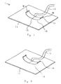
- a loudspeaker 1 comprises a plate 11 capable of supporting resonant bending wave modes, as set out in W097/09842.
- a curved, composite piezoelectric device 13 such as described in US 5632841 has an attachment portion 12 centrally located on the piezoelectric device.
- the attachment portion 12 is mounted on a preferred, off-centre location on the panel 11.
- the ends 14 of the device are free.
- a mass 15 is provided along the end of the piezoelectric device to mass-load the piezoelectric vibration exciter to increase the output of the exciter.
- Fig.2 shows a similar arrangement except that instead of a single mass 15, a pair of masses 19 are provided at each end of the piezoelectric vibration exciter 13.
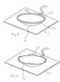
- the piezoelectric vibration exciter 21 is genuinely circular, attached to the panel at the centre of the circle, with a single mass 23 provided on the free peripheral rim 25 of the exciter.
- the mass 23 mass-loads the piezoelectric vibration exciter to increase the output of the exciter.
- Fig. 4 shows an alternative arrangement in which the continuous ring 23 of Fig. 3 is replaced by a plurality of discreet masses 27, symmetrically arranged the rim 25 of the piezoelectric device.
- the invention thus provides a simple way of increasing the output of an exciter.
Landscapes
- Physics & Mathematics (AREA)
- Engineering & Computer Science (AREA)
- Acoustics & Sound (AREA)
- Signal Processing (AREA)
- Piezo-Electric Transducers For Audible Bands (AREA)
- Apparatuses For Generation Of Mechanical Vibrations (AREA)
Description
a mass load provided on at least one of the or each free portion.
Claims (11)
- A vibration exciter comprising
a curved piezoelectric device (13) having an attachment portion (12) at which the device is to be attached to a substrate to be vibrated (11) and at least one free end or peripheral rim portion (14) remote from the attachment portion (12), and
a mass load provided on at least one of the or each free end or peripheral rim portion. - A vibration exciter according to claim 1 wherein the piezoelectric device (13) is a ferroelectric device.
- A vibrations exciter according to claim 2 wherein the ferroelectric piezoelectric device is a pre-stressed device.
- A vibration exciter according to any preceding claim wherein the piezoelectric device is arcuate.
- A vibration exciter according to any of claims 1 to 3 wherein the piezoelectric device is dish-shaped.
- A loudspeaker comprising
a diaphragm (11) capable of vibration to produce sound,
a curved piezoelectric device (13) having an attachment portion (12) mounted to the diaphragm and at least one free end or peripheral rim portion (14) remote from the attachment portion (12), and
a mass load provided on at least one of the or each free end or peripheral rim portion (14). - A loudspeaker according to claim 6 wherein the diaphragm (11) is a panel capable of supporting bending waves and the piezoelectric device (13) is arranged to excite bending waves in the panel.
- A loudspeaker according to claim 6 or .7 wherein the piezoelectric device (13) is a ferroelectric device.
- A loudspeaker according to claim 8 wherein the ferroelectric device (13) is a pre-stressed device.
- A loudspeaker according to any of claims 6 to 9 wherein the piezoelectric device (13) is arcuate.
- A loudspeaker according to any of claims 6 to 9 wherein the piezoelectric device (13) is dish-shaped.
Applications Claiming Priority (3)
| Application Number | Priority Date | Filing Date | Title |
|---|---|---|---|
| GBGB9910216.2A GB9910216D0 (en) | 1999-04-29 | 1999-04-29 | Vibration exciter |
| GB9910216 | 1999-04-29 | ||
| PCT/GB2000/001485 WO2000067525A2 (en) | 1999-04-29 | 2000-04-28 | Piezoelectric vibration exciter |
Publications (2)
| Publication Number | Publication Date |
|---|---|
| EP1172019A2 EP1172019A2 (en) | 2002-01-16 |
| EP1172019B1 true EP1172019B1 (en) | 2003-09-17 |
Family
ID=10852721
Family Applications (1)
| Application Number | Title | Priority Date | Filing Date |
|---|---|---|---|
| EP00927419A Expired - Lifetime EP1172019B1 (en) | 1999-04-29 | 2000-04-28 | Piezoelecric vibration exciter |
Country Status (8)
| Country | Link |
|---|---|
| EP (1) | EP1172019B1 (en) |
| JP (1) | JP2002543727A (en) |
| CN (1) | CN1343438A (en) |
| AU (1) | AU4582400A (en) |
| DE (1) | DE60005329D1 (en) |
| GB (1) | GB9910216D0 (en) |
| TW (1) | TW472497B (en) |
| WO (1) | WO2000067525A2 (en) |
Cited By (1)
| Publication number | Priority date | Publication date | Assignee | Title |
|---|---|---|---|---|
| DE102021213003A1 (en) | 2021-11-18 | 2023-05-25 | Continental Automotive Technologies GmbH | Transducer for generating sound waves and display |
Families Citing this family (1)
| Publication number | Priority date | Publication date | Assignee | Title |
|---|---|---|---|---|
| WO2009001769A1 (en) * | 2007-06-27 | 2008-12-31 | Alps Electric Co., Ltd. | Electrostriction actuator module |
Family Cites Families (5)
| Publication number | Priority date | Publication date | Assignee | Title |
|---|---|---|---|---|
| JPS5819099A (en) * | 1981-07-27 | 1983-02-03 | Murata Mfg Co Ltd | Piezoelectric type loud speaker |
| GB2166022A (en) * | 1984-09-05 | 1986-04-23 | Sawafuji Dynameca Co Ltd | Piezoelectric vibrator |
| US5115472A (en) * | 1988-10-07 | 1992-05-19 | Park Kyung T | Electroacoustic novelties |
| UA51671C2 (en) * | 1995-09-02 | 2002-12-16 | Нью Транзд'Юсез Лімітед | Acoustic device |
| BE1011085A4 (en) * | 1997-04-03 | 1999-04-06 | Sonitron Naamloze Vennootschap | ELEMENT FOR PLAYING AND / OR RECORDING SOUND. |
-
1999
- 1999-04-29 GB GBGB9910216.2A patent/GB9910216D0/en not_active Ceased
-
2000
- 2000-04-28 AU AU45824/00A patent/AU4582400A/en not_active Abandoned
- 2000-04-28 DE DE60005329T patent/DE60005329D1/en not_active Expired - Lifetime
- 2000-04-28 WO PCT/GB2000/001485 patent/WO2000067525A2/en not_active Ceased
- 2000-04-28 EP EP00927419A patent/EP1172019B1/en not_active Expired - Lifetime
- 2000-04-28 JP JP2000614776A patent/JP2002543727A/en active Pending
- 2000-04-28 CN CN00804709.XA patent/CN1343438A/en active Pending
- 2000-05-04 TW TW089108521A patent/TW472497B/en not_active IP Right Cessation
Cited By (1)
| Publication number | Priority date | Publication date | Assignee | Title |
|---|---|---|---|---|
| DE102021213003A1 (en) | 2021-11-18 | 2023-05-25 | Continental Automotive Technologies GmbH | Transducer for generating sound waves and display |
Also Published As
| Publication number | Publication date |
|---|---|
| DE60005329D1 (en) | 2003-10-23 |
| WO2000067525A3 (en) | 2001-03-08 |
| JP2002543727A (en) | 2002-12-17 |
| AU4582400A (en) | 2000-11-17 |
| EP1172019A2 (en) | 2002-01-16 |
| GB9910216D0 (en) | 1999-06-30 |
| CN1343438A (en) | 2002-04-03 |
| WO2000067525A2 (en) | 2000-11-09 |
| TW472497B (en) | 2002-01-11 |
Similar Documents
| Publication | Publication Date | Title |
|---|---|---|
| EP1250827B1 (en) | Transducer | |
| US7635941B2 (en) | Transducer | |
| JP5012512B2 (en) | Piezoelectric actuator and electronic device | |
| KR100460818B1 (en) | Panel-form loudspeaker | |
| EP1101387B1 (en) | Acoustic device using bending wave modes | |
| EP1762119B1 (en) | Piezoelectric inertial transducer | |
| JP4080870B2 (en) | Loudspeaker driver | |
| JP2003507949A (en) | Electroacoustic transducer and method with fixed diaphragm structure | |
| US6888946B2 (en) | High frequency loudspeaker | |
| EP1172019B1 (en) | Piezoelecric vibration exciter | |
| US6342749B1 (en) | Vibration exciter | |
| KR20020040546A (en) | The apparatus for generating vibrations | |
| JP3418840B2 (en) | Silent vibration alarm | |
| WO2006052970A2 (en) | Flexural cylinder projector | |
| WO2000054549A2 (en) | Vibration exciters for driving bending wave panels | |
| KR20060097839A (en) | Piezoelectric vibrator vibrating on both sides and piezoelectric flat panel speaker using the same | |
| JP3528041B2 (en) | Speaker | |
| JPH0422400B2 (en) | ||
| JP2000350292A (en) | Vibration generating device | |
| JPH08336196A (en) | Piezoelectric speaker | |
| GB2433174A (en) | Exciter for a bending wave distributed mode loudspeaker | |
| ZA200205051B (en) | Transducer. | |
| HK1099881B (en) | Piezoelectric inertial transducer | |
| AU5710399A (en) | Vibration actuator for pager | |
| RU99126439A (en) | VIBRATION CONVERTERS FOR RESONANCE PANEL PERFORMANCE SPEAKER AND SPEAKER WITH SUCH CONVERTERS |
Legal Events
| Date | Code | Title | Description |
|---|---|---|---|
| PUAI | Public reference made under article 153(3) epc to a published international application that has entered the european phase |
Free format text: ORIGINAL CODE: 0009012 |
|
| AK | Designated contracting states |
Kind code of ref document: A2 Designated state(s): AT BE CH CY DE DK ES FI FR GB GR IE IT LI LU MC NL PT SE |
|
| AX | Request for extension of the european patent |
Free format text: AL;LT;LV;MK;RO;SI |
|
| 17P | Request for examination filed |
Effective date: 20011116 |
|
| GRAH | Despatch of communication of intention to grant a patent |
Free format text: ORIGINAL CODE: EPIDOS IGRA |
|
| GRAS | Grant fee paid |
Free format text: ORIGINAL CODE: EPIDOSNIGR3 |
|
| GRAA | (expected) grant |
Free format text: ORIGINAL CODE: 0009210 |
|
| AK | Designated contracting states |
Kind code of ref document: B1 Designated state(s): DE FR GB IT |
|
| PG25 | Lapsed in a contracting state [announced via postgrant information from national office to epo] |
Ref country code: IT Free format text: LAPSE BECAUSE OF FAILURE TO SUBMIT A TRANSLATION OF THE DESCRIPTION OR TO PAY THE FEE WITHIN THE PRE;WARNING: LAPSES OF ITALIAN PATENTS WITH EFFECTIVE DATE BEFORE 2007 MAY HAVE OCCURRED AT ANY TIME BEFORE 2007. THE CORRECT EFFECTIVE DATE MAY BE DIFFERENT FROM THE ONE RECORDED.SCRIBED TIME-LIMIT Effective date: 20030917 Ref country code: FR Free format text: LAPSE BECAUSE OF FAILURE TO SUBMIT A TRANSLATION OF THE DESCRIPTION OR TO PAY THE FEE WITHIN THE PRESCRIBED TIME-LIMIT Effective date: 20030917 |
|
| REG | Reference to a national code |
Ref country code: GB Ref legal event code: FG4D |
|
| REF | Corresponds to: |
Ref document number: 60005329 Country of ref document: DE Date of ref document: 20031023 Kind code of ref document: P |
|
| REG | Reference to a national code |
Ref country code: IE Ref legal event code: FG4D |
|
| PG25 | Lapsed in a contracting state [announced via postgrant information from national office to epo] |
Ref country code: DE Free format text: LAPSE BECAUSE OF FAILURE TO SUBMIT A TRANSLATION OF THE DESCRIPTION OR TO PAY THE FEE WITHIN THE PRESCRIBED TIME-LIMIT Effective date: 20031218 |
|
| LTIE | Lt: invalidation of european patent or patent extension |
Effective date: 20030917 |
|
| PLBE | No opposition filed within time limit |
Free format text: ORIGINAL CODE: 0009261 |
|
| STAA | Information on the status of an ep patent application or granted ep patent |
Free format text: STATUS: NO OPPOSITION FILED WITHIN TIME LIMIT |
|
| 26N | No opposition filed |
Effective date: 20040618 |
|
| EN | Fr: translation not filed | ||
| REG | Reference to a national code |
Ref country code: IE Ref legal event code: MM4A |
|
| PGFP | Annual fee paid to national office [announced via postgrant information from national office to epo] |
Ref country code: GB Payment date: 20060316 Year of fee payment: 7 |
|
| GBPC | Gb: european patent ceased through non-payment of renewal fee |
Effective date: 20070428 |
|
| PG25 | Lapsed in a contracting state [announced via postgrant information from national office to epo] |
Ref country code: GB Free format text: LAPSE BECAUSE OF NON-PAYMENT OF DUE FEES Effective date: 20070428 |