EP1171211B1 - Efg crystal growth apparatus - Google Patents
Efg crystal growth apparatus Download PDFInfo
- Publication number
- EP1171211B1 EP1171211B1 EP00916008A EP00916008A EP1171211B1 EP 1171211 B1 EP1171211 B1 EP 1171211B1 EP 00916008 A EP00916008 A EP 00916008A EP 00916008 A EP00916008 A EP 00916008A EP 1171211 B1 EP1171211 B1 EP 1171211B1
- Authority
- EP
- European Patent Office
- Prior art keywords
- crucible
- susceptor
- side wall
- selected material
- die
- Prior art date
- Legal status (The legal status is an assumption and is not a legal conclusion. Google has not performed a legal analysis and makes no representation as to the accuracy of the status listed.)
- Expired - Lifetime
Links
- 230000012010 growth Effects 0.000 title claims description 28
- 239000013078 crystal Substances 0.000 title description 8
- 229910052710 silicon Inorganic materials 0.000 claims description 29
- 239000010703 silicon Substances 0.000 claims description 29
- 239000000463 material Substances 0.000 claims description 20
- 239000007787 solid Substances 0.000 claims description 13
- 239000007788 liquid Substances 0.000 claims description 11
- 238000000034 method Methods 0.000 claims description 11
- 239000002245 particle Substances 0.000 claims description 9
- 230000008569 process Effects 0.000 claims description 9
- 239000010453 quartz Substances 0.000 claims description 6
- VYPSYNLAJGMNEJ-UHFFFAOYSA-N silicon dioxide Inorganic materials O=[Si]=O VYPSYNLAJGMNEJ-UHFFFAOYSA-N 0.000 claims description 6
- 230000009471 action Effects 0.000 claims description 5
- 238000010438 heat treatment Methods 0.000 claims description 5
- XUIMIQQOPSSXEZ-UHFFFAOYSA-N Silicon Chemical compound [Si] XUIMIQQOPSSXEZ-UHFFFAOYSA-N 0.000 description 28
- 238000005231 Edge Defined Film Fed Growth Methods 0.000 description 19
- OKTJSMMVPCPJKN-UHFFFAOYSA-N Carbon Chemical compound [C] OKTJSMMVPCPJKN-UHFFFAOYSA-N 0.000 description 15
- 229910002804 graphite Inorganic materials 0.000 description 15
- 239000010439 graphite Substances 0.000 description 15
- 239000000155 melt Substances 0.000 description 12
- 235000001674 Agaricus brunnescens Nutrition 0.000 description 9
- 239000011856 silicon-based particle Substances 0.000 description 8
- 238000007711 solidification Methods 0.000 description 5
- 230000008023 solidification Effects 0.000 description 5
- 238000009826 distribution Methods 0.000 description 3
- 230000002093 peripheral effect Effects 0.000 description 3
- 230000002028 premature Effects 0.000 description 3
- 230000008901 benefit Effects 0.000 description 2
- 239000007789 gas Substances 0.000 description 2
- 238000009413 insulation Methods 0.000 description 2
- 238000004519 manufacturing process Methods 0.000 description 2
- 230000004048 modification Effects 0.000 description 2
- 238000012986 modification Methods 0.000 description 2
- NJPPVKZQTLUDBO-UHFFFAOYSA-N novaluron Chemical compound C1=C(Cl)C(OC(F)(F)C(OC(F)(F)F)F)=CC=C1NC(=O)NC(=O)C1=C(F)C=CC=C1F NJPPVKZQTLUDBO-UHFFFAOYSA-N 0.000 description 2
- 239000000758 substrate Substances 0.000 description 2
- 238000009736 wetting Methods 0.000 description 2
- 241001669573 Galeorhinus galeus Species 0.000 description 1
- 230000002411 adverse Effects 0.000 description 1
- 230000000712 assembly Effects 0.000 description 1
- 238000000429 assembly Methods 0.000 description 1
- 230000015572 biosynthetic process Effects 0.000 description 1
- 238000010276 construction Methods 0.000 description 1
- 230000008878 coupling Effects 0.000 description 1
- 238000010168 coupling process Methods 0.000 description 1
- 238000005859 coupling reaction Methods 0.000 description 1
- 238000005336 cracking Methods 0.000 description 1
- 230000009977 dual effect Effects 0.000 description 1
- 230000036433 growing body Effects 0.000 description 1
- 230000006698 induction Effects 0.000 description 1
- 239000011261 inert gas Substances 0.000 description 1
- 230000007246 mechanism Effects 0.000 description 1
- 239000000289 melt material Substances 0.000 description 1
- -1 octagons Chemical compound 0.000 description 1
- HBMJWWWQQXIZIP-UHFFFAOYSA-N silicon carbide Chemical compound [Si+]#[C-] HBMJWWWQQXIZIP-UHFFFAOYSA-N 0.000 description 1
- 238000006467 substitution reaction Methods 0.000 description 1
- 230000008719 thickening Effects 0.000 description 1
- 235000012431 wafers Nutrition 0.000 description 1
Images




Classifications
-
- C—CHEMISTRY; METALLURGY
- C30—CRYSTAL GROWTH
- C30B—SINGLE-CRYSTAL GROWTH; UNIDIRECTIONAL SOLIDIFICATION OF EUTECTIC MATERIAL OR UNIDIRECTIONAL DEMIXING OF EUTECTOID MATERIAL; REFINING BY ZONE-MELTING OF MATERIAL; PRODUCTION OF A HOMOGENEOUS POLYCRYSTALLINE MATERIAL WITH DEFINED STRUCTURE; SINGLE CRYSTALS OR HOMOGENEOUS POLYCRYSTALLINE MATERIAL WITH DEFINED STRUCTURE; AFTER-TREATMENT OF SINGLE CRYSTALS OR A HOMOGENEOUS POLYCRYSTALLINE MATERIAL WITH DEFINED STRUCTURE; APPARATUS THEREFOR
- C30B29/00—Single crystals or homogeneous polycrystalline material with defined structure characterised by the material or by their shape
- C30B29/02—Elements
- C30B29/06—Silicon
-
- C—CHEMISTRY; METALLURGY
- C30—CRYSTAL GROWTH
- C30B—SINGLE-CRYSTAL GROWTH; UNIDIRECTIONAL SOLIDIFICATION OF EUTECTIC MATERIAL OR UNIDIRECTIONAL DEMIXING OF EUTECTOID MATERIAL; REFINING BY ZONE-MELTING OF MATERIAL; PRODUCTION OF A HOMOGENEOUS POLYCRYSTALLINE MATERIAL WITH DEFINED STRUCTURE; SINGLE CRYSTALS OR HOMOGENEOUS POLYCRYSTALLINE MATERIAL WITH DEFINED STRUCTURE; AFTER-TREATMENT OF SINGLE CRYSTALS OR A HOMOGENEOUS POLYCRYSTALLINE MATERIAL WITH DEFINED STRUCTURE; APPARATUS THEREFOR
- C30B15/00—Single-crystal growth by pulling from a melt, e.g. Czochralski method
- C30B15/34—Edge-defined film-fed crystal-growth using dies or slits
-
- C—CHEMISTRY; METALLURGY
- C30—CRYSTAL GROWTH
- C30B—SINGLE-CRYSTAL GROWTH; UNIDIRECTIONAL SOLIDIFICATION OF EUTECTIC MATERIAL OR UNIDIRECTIONAL DEMIXING OF EUTECTOID MATERIAL; REFINING BY ZONE-MELTING OF MATERIAL; PRODUCTION OF A HOMOGENEOUS POLYCRYSTALLINE MATERIAL WITH DEFINED STRUCTURE; SINGLE CRYSTALS OR HOMOGENEOUS POLYCRYSTALLINE MATERIAL WITH DEFINED STRUCTURE; AFTER-TREATMENT OF SINGLE CRYSTALS OR A HOMOGENEOUS POLYCRYSTALLINE MATERIAL WITH DEFINED STRUCTURE; APPARATUS THEREFOR
- C30B29/00—Single crystals or homogeneous polycrystalline material with defined structure characterised by the material or by their shape
- C30B29/60—Single crystals or homogeneous polycrystalline material with defined structure characterised by the material or by their shape characterised by shape
- C30B29/66—Crystals of complex geometrical shape, e.g. tubes, cylinders
-
- C—CHEMISTRY; METALLURGY
- C30—CRYSTAL GROWTH
- C30B—SINGLE-CRYSTAL GROWTH; UNIDIRECTIONAL SOLIDIFICATION OF EUTECTIC MATERIAL OR UNIDIRECTIONAL DEMIXING OF EUTECTOID MATERIAL; REFINING BY ZONE-MELTING OF MATERIAL; PRODUCTION OF A HOMOGENEOUS POLYCRYSTALLINE MATERIAL WITH DEFINED STRUCTURE; SINGLE CRYSTALS OR HOMOGENEOUS POLYCRYSTALLINE MATERIAL WITH DEFINED STRUCTURE; AFTER-TREATMENT OF SINGLE CRYSTALS OR A HOMOGENEOUS POLYCRYSTALLINE MATERIAL WITH DEFINED STRUCTURE; APPARATUS THEREFOR
- C30B35/00—Apparatus not otherwise provided for, specially adapted for the growth, production or after-treatment of single crystals or of a homogeneous polycrystalline material with defined structure
-
- Y—GENERAL TAGGING OF NEW TECHNOLOGICAL DEVELOPMENTS; GENERAL TAGGING OF CROSS-SECTIONAL TECHNOLOGIES SPANNING OVER SEVERAL SECTIONS OF THE IPC; TECHNICAL SUBJECTS COVERED BY FORMER USPC CROSS-REFERENCE ART COLLECTIONS [XRACs] AND DIGESTS
- Y10—TECHNICAL SUBJECTS COVERED BY FORMER USPC
- Y10T—TECHNICAL SUBJECTS COVERED BY FORMER US CLASSIFICATION
- Y10T117/00—Single-crystal, oriented-crystal, and epitaxy growth processes; non-coating apparatus therefor
- Y10T117/10—Apparatus
- Y10T117/1024—Apparatus for crystallization from liquid or supercritical state
- Y10T117/1032—Seed pulling
- Y10T117/1036—Seed pulling including solid member shaping means other than seed or product [e.g., EDFG die]
- Y10T117/104—Means for forming a hollow structure [e.g., tube, polygon]
Definitions
- This invention relates to apparatus for growing crystalline bodies from a melt by the Edge-defined Film-fed Growth (“EFG”) process, and more particularly to an improved die/susceptor assembly for use in growing hollow crystalline bodies by the EFG process.
- EFG Edge-defined Film-fed Growth
- tubular crystalline bodies e.g., hollow bodies with round or polygonal cross-sections
- tubular crystalline bodies are grown on a seed from a liquid film of a selected feed material which is transported by capillary action from a melt contained in a crucible through one or more capillaries in a die to the top end surface of the die.
- EFG dies typically comprise a top end surface, inner and outer side surfaces which intersect the top end surface, and at least one capillary, i.e., a passageway of capillary proportions, having an upper end which terminates at the top end surface of the die and a lower end which communicates with the melt in the crucible.
- the shape of the crystalline body is determined by the external or edge configuration of the top end surface of the die.
- Polygonally-shaped hollow bodies of silicon e.g., "nonagons” or “octagons” grown by EFG process are subdivided at their corners into a plurality of flat substrates that are used to form photovoltaic solar cells.
- EFG dies for growing silicon octagons are exemplified by U.S. Patents Nos. 4,230,674 issued to A. S. Taylor et al. , and 4,647,437 issued to R. W. Stormont et al .
- One object of the present invention is to provide an improved EFG die/crucible/susceptor assembly for growing hollow bodies that substantially prevents or minimizes undesired solidification of melt material near the center region of the die.
- Another object of the present invention is to provide an improved EFG die/susceptor/crucible assembly that is designed to prevent damage to the susceptor underlying the die during cool-down of the crystal growth apparatus.
- a further object is to reduce wetting between molten silicon and certain components associated with the center hub region of the EFG die/crucible assembly.
- Another object of the invention is to reduce die temperature variations resulting from solidification of silicon onto members associated with the EFG die.
- Still another object of the invention is to provide a new and improved method of growing a tubular crystalline body from a pool of melt.
- the objective of this invention is to redesign the EFG die and the susceptor to eliminate the mushroom problems during the crystal growth, and to prevent the die from cracking the reusable susceptors during the cool-down.
- Fig. 1 illustrates conventional EFG crystal growth apparatus for growing tubular bodies.
- Fig. 1 shows a crucible/capillary die unit 20, made in accordance with the teachings of U.S. Patent No. 5,037,622 , installed in a furnace that comprises an enclosure 24 (only part of which is shown for simplicity of illustration), and a heating coil 26 surrounding enclosure 24.
- the crucible/die unit includes a short, open-topped crucible comprising an upstanding outer side wall 32, a bottom wall 34 and an annular inner side wall 36 which forms an annular hub. Outer side wall 32, bottom wall 34 and inner side wall 36 together define an annular space in which a melt 38 is contained.
- the outer side wall 32 includes a capillary die portion that has substantially the same construction as the one illustrated in Figs. 3-7 of said U.S. Patent No. 5,037,622 .
- the apparatus of Fig. 1 further includes a heat susceptor 40 which is positioned directly below and serves as a support for crucible/capillary die unit 20.
- a pedestal mounted in furnace enclosure 24 acts as a support for susceptor 40 and crucible/die unit 20.
- U.S. Patent No. 5,156,978 issued to B. R. Bathey illustrates use of a pedestal for supporting a susceptor and crucible in a furnace.
- Susceptor 40 is made of graphite or other suitable material and is heated by suscepting electromagnetic energy generated by heating coil 26. Susceptor 40 transmits its heat to the crucible/die unit 20 so as to maintain the silicon in the crucible in a molten state.
- the central hub 36 of the die/crucible unit 20 defines a center hole 43 which is counterbored so as to form a shoulder 44.
- Susceptor 40 has a center hole 46 which is counterbored so as to form a shoulder 48.
- Susceptor 40 also has an annular projection or hub 50 on its upper side concentric with its center hole 46. Hub 50 extends into and makes a close fit with the center hole of hub 36, with shoulder 44 overlapping susceptor hub 50.
- One or more locator pins 52 disposed in holes in the under side of the crucible/die unit and the upper side of the susceptor serve to properly orient those members relative to one another.
- both the susceptor as well as the die are shaped to conform generally to that cross-sectional configuration.
- the center hole 46 of the susceptor is filled with a multiple layers 52 of graphite felt insulation which surround a feed tube 54 that is connected to a melt replenishment system represented schematically at 56 that is adapted for delivering solid particles of silicon feed stock through into the region above the crucible, from which region the particles fall down into melt 38.
- melt replenishment systems may be used with the apparatus shown in Fig. 1 , provided that they are controlled so as to maintain the level of melt in crucible 24 within the limits suggested in said U.S. Patent No. 5,037,622 .
- Suitable melt replenishment systems are described in U.S. Patents Nos. 4,968,380 issued to G. M. Freedman et al. ; 5,085,728 issued to B. H. Mackintosh et al. ; and 5,098,229 issued to F. U. Meier et al .
- a standoff ring 60 mounted on the center hub of the crucible/die unit 20 is a standoff ring 60 made of graphite, and overlying hub 50 of the susceptor and the graphite felt insulation is an annular graphite plate or disk 62 that has an annular flange 64 at its inner edge.
- a silicon feed distributor or director member 66 having a conically-shaped upper surface 68 is supported near its outer edge by ring 60.
- Feed distributor member 66 also is made of graphite and has a center hole that accommodates the top end of delivery tube 54 and a depending tubular extension 70 that sits on flange 64 of plate 62.
- Distributor member 66 functions like an umbrella in that it intercepts falling silicon particles which then slide down its sloped upper surface 68 and spill into the crucible.
- the apparatus of Fig. 1 also includes a hat-shaped member 72 that encloses distributor member 66.
- Member 72 comprises a side wall 74, a top wall 76, and a peripheral flange 78 at the bottom edge of the side wall.
- Member 72 is made of graphite and its flange 78 sits on a plurality of standoff pins 80 that that are mounted in blind holes in bottom wall 34 of the crucible/die unit.
- the center of member 72 is provided with a replaceable graphite insert 82 that acts as a deflector of silicon particles delivered via feed tube 54.
- Member 72 has a dual function. It acts as a plenum to contain and slowly release the gas used to transport silicon particles up feed tube 54.
- Member 72 also acts as an inner afterheater for the growing body 88.
- a second afterheater like the one shown at 28 in said U.S. Patent No. 5,037,622 , surround the bottom end of the growing crystalline body 88 so as to provide better control of the temperature of that body in the region just above the growth interface.
- the apparatus of Fig. 1 additionally comprises a seed holder schematically illustrated at 90 for holding a seed (not shown) onto which the crystalline body 88 is grown.
- the seed usually takes the form of a short section of a previously grown crystalline body so as to facilitate startup of the growth process.
- Seed holder 90 is attached to a pulling mechanism 92 which is adapted to move seed holder 90 axially toward and away from capillary die/crucible unit 20.
- crucible/die unit 20 is heated by induction heating through the graphite susceptor 40.
- spherical silicon particles are continuously fed through the feed pipe 54 by a jet of inert gas.
- the particles discharged from pipe 54 are contained by graphite member 72 functioning as a plenum.
- the discharged silicon particles impinge upon deflector 82 which deflects them back onto the upper surface 68 of umbrella-shaped feed distributor member 66.
- the crystalline body 88 grown and pulled from the graphite die is an "octagon", i.e., it is a tube having an octagonal cross-sectional configuration.
- the problem commences with the existence of some local cold spots at the center region of the crucible/die unit, which tend to cause some molten silicon to solidify in that center region.
- the vertical surface tension gradient resulting from the temperature variation acts to pull molten silicon from the melt 38 in the crucible up along the adjacent surface of inside wall 36 toward the standoff ring 60.
- the molten silicon is continuously transported to the center hub region by this surface tension gradient-driven convection.
- Molten silicon easily wets graphite; as a result some of the molten silicon is caused by the surface tension gradient to reach and wet ring 60. Silicon solidifies on the standoff ring which is cooler than the crucible/die unit.
- the solidified silicon on ring 60 grows outward and forms a mushroom-like solid piece ("mushroom" for short).
- the mushroom even grows onto the peripheral portion of umbrella-shaped member 70.
- the mushroom shaped solid continues to grow, it begins to block new silicon particles from reaching the melt and also causes severe non-uniformity in the circumferential temperature distribution at the growth interface.
- the solid "mushroom” grows large enough to prevent any significant amount of silicon from falling into the crucible, resulting in premature termination of growth due to depletion of the supply of melt 38 in the crucible.
- fluctuations in temperature can cause relatively large chunks of unmelted silicon to suddenly break from the mushroom and fall into the melt, which causes the crucible to overfill and flood, a condition that usually results in termination of growth.
- the non-uniform temperature distribution at the growth interface leads to an undesirably large variation in the wall thickness, which in turn reduces the total yield of acceptable silicon wafers cut from the grown hollow body.
- Fig. 1 also tends to suffer from a second problem that occurs during cool-down of the apparatus after a growth run is finished, particularly when the growth run is terminated prematurely.
- Molten silicon expands upon solidification.
- silicon remaining in the crucible will expand and as it solidifies, it will cause the annular wall 36 at the center of the crucible/die unit to shrink, thereby reducing its inside diameter.
- Shrinkage of the inside diameter of wall 36 results in that wall exerting a radial compressive force on the hub portion 50 of susceptor 40, causing that hub portion 50 to fracture. This necessitates removal and replacement of the susceptor. If not for such fracture damage, the susceptor could be reused many times.
- the present invention provides a crucible/die unit 20A, a susceptor 40A and a standoff ring 60A which improve upon the corresponding components 20, 40 and 60 described above and are intended to replace the same in the growth apparatus of Fig. 1 .
- the one-piece crucible/die unit 20A embodies the design disclosed by said U.S. Patent No. 5,037,622 and is substantially the same as the crucible/die unit 20 shown in Fig. 1 .
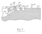
- the unit 20A comprises a capillary die 19 ( Fig. 3 ) that is integral with and projects above the tope end surface of the outer side wall 32.
- the die 19 includes an upstanding die tip 100 having a top surface 102, inner and outer outside surfaces 104 and 106, and a central capillary slot 108.
- the crucible/die unit 20A further includes an inner moat 114, an outer moat 116, and an overflow moat 118 formed in the upper end surface of outer side wall 32.
- the shape of inner moat 114 corresponds to that of die tip 100.
- inner moat 114 also has an octagon configuration.
- Die 19 also includes a plurality of circumferentially-spaced inclined passageways 120 formed in the outer side wall 32.
- Passageways 120 correspond to the passageways 180 of U.S. Patent No. 5,037,622 .
- Passageways 120 are positioned so that they intersect (1) moat 114, capillary slot 108, and (3) moat 116.
- inclined passageways 120 couple inner and outer moats 114 and 116 and capillary slot 108 with the interior of the crucible thereby permitting liquid silicon to be conducted by capillary action from the melt 38 in the crucible to the inner and outer moats and capillary slot 108.
- other details of the capillary die portion of crucible/die unit 20A are essentially the same as those of the preferred form of crucible/die design shown in U.S. Patent No. 5,037,622 .
- crucible/die unit 20A differs from the corresponding unit 20 shown in Fig. 1 in that its center hole 43 lacks the flange 44 and instead the center hole 43 has a constant diameter.
- the bottom wall 34 is formed with a downwardly-extending annular projection or neck portion 124 whose inner and outer surfaces are cylindrical.
- the inner side wall 36 of crucible/die unit 20A can be made thicker than the corresponding wall 36 of the crucible/die unit 20. As noted below, the thicker inner side wall helps reduce variations in temperature.
- the susceptor 40A is like susceptor 40 but differs therefrom in that its center hole 46 is counterbored at its top end so as to form an annular recess 126 that is sized to receive neck portion 124 in a close fit.
- the upper surface of susceptor 40A has a raised annular portion 128 surrounding its center hole. The presence of an annular portion as shown at 128 is not new.
- the periphery of susceptor 40A has a generally octagonal configuration so as to match a corresponding peripheral configuration (not shown) defined by the outer surface of the outer side wall 32 of crucible/die unit 20A.
- Susceptor 40A is oriented so that its eight flat outer surfaces 41 are aligned with corresponding outer surfaces of outer side wall 32.
- Standoff ring 60A is like standoff ring 60, except that it is made of quartz instead of graphite. Molten silicon does not wet quartz as easily as it wets graphite, and the substitution of ring 60A for ring 60 is accomplished to substantially reduce the tendency to form a mushroom solid as described above.
- the new design reverses the coupling between the die and the susceptor.
- the crucible/die unit has its neck portion 124 extend into groove 126 of the susceptor, when the apparatus is cooled down the die is free to contract radially, thereby avoiding any danger of it fracturing the susceptor.
- the apparatus improvements also eliminate the mushroom problems described above by (a) reducing the wetting between molten silicon and the center region as a consequence of replacing the graphite hub ring 60 with the quartz hub ring 60A; and (b) reducing cold spots by thickening the inner side wall 36 of crucible/die unit 20A, which improves the heating up of the center hub region. Eliminating the mushroom problems assures that the incoming silicon particles will spill into and form part of the melt 38, instead of piling up and forming a solidified mass on and around the distributor member 66.
- a further advantage is that installing the improved crucible/die unit 20A, susceptor 40A and standoff ring 60A in crystal growth apparatus as shown in Fig. 1 does not require any further changes to that apparatus or to the method of growing hollow bodies.
- the present invention retains all of the advantages of the invention disclosed and claimed in said U.S. Patent No. 5,037,622 .
- the top end surface of the capillary die may have circular, elliptical, triangular, rectangular, or other configurations, depending upon what shape body is to be grown.
- the relative dimensions of different portions of the die/crucible unit 20A, the susceptor 40A and the standoff ring 60A may be varied.
- Other changes in the design of the crucible/die assembly also may be made without departing from the principles of the present invention.
- the crucible and EFG die may be formed as two separate and distinct members that are assembled to one another so as to form the functional equivalent of the integral crucible/die unit 20A shown in the drawings.
- tubular means a hollow elongate body having a cross-sectional shape in the form of a ring that preferably has a polygonal configuration, e.g., an octagon or nonagon, but alternatively may have a circular or other configuration; also the term annular is intended to embrace rings that have a polygonal, circular or other shape.
Landscapes
- Chemical & Material Sciences (AREA)
- Engineering & Computer Science (AREA)
- Crystallography & Structural Chemistry (AREA)
- Materials Engineering (AREA)
- Metallurgy (AREA)
- Organic Chemistry (AREA)
- Physics & Mathematics (AREA)
- Geometry (AREA)
- Crystals, And After-Treatments Of Crystals (AREA)
- Liquid Deposition Of Substances Of Which Semiconductor Devices Are Composed (AREA)
Description
- This invention was made under Subcontract No. ZAF-6-14271-13, which is a subcontract under U.S. Prime Contract No. DE-AC36-83CH10093.
- This invention relates to apparatus for growing crystalline bodies from a melt by the Edge-defined Film-fed Growth ("EFG") process, and more particularly to an improved die/susceptor assembly for use in growing hollow crystalline bodies by the EFG process.
- In the EFG process tubular crystalline bodies, e.g., hollow bodies with round or polygonal cross-sections, are grown on a seed from a liquid film of a selected feed material which is transported by capillary action from a melt contained in a crucible through one or more capillaries in a die to the top end surface of the die. EFG dies typically comprise a top end surface, inner and outer side surfaces which intersect the top end surface, and at least one capillary, i.e., a passageway of capillary proportions, having an upper end which terminates at the top end surface of the die and a lower end which communicates with the melt in the crucible. The shape of the crystalline body is determined by the external or edge configuration of the top end surface of the die. Polygonally-shaped hollow bodies of silicon, e.g., "nonagons" or "octagons", grown by EFG process are subdivided at their corners into a plurality of flat substrates that are used to form photovoltaic solar cells. Early designs of EFG dies for growing silicon octagons are exemplified by
U.S. Patents Nos. 4,230,674 issued to A. S. Taylor et al. , and4,647,437 issued to R. W. Stormont et al . - Use of the EFG process is complicated by the fact that variations in temperature tend to exist around the circumference of an EFG die when the die is used to grow crystalline bodies. Variations in thermal symmetry around the circumference of the die can cause local changes in thickness of the growing crystalline body. Such variations in thickness may be severe enough to render the crystalline body more susceptible to fracture, thereby reducing the number of solar cells which can be produced from the hollow polygonal crystalline body, inasmuch as the thinner substrates cut from the crystalline body tend to be prone to breakage. Significant variations in temperature around the circumference of the die also make it difficult to sustain growth, resulting in rupturing of the liquid menisci that extend between the die and the growing crystal body. When the menisci are ruptured, i.e., when the liquid/solid growth interface is terminated, liquid silicon tends to splash or overflow onto inner and/or outer surfaces of the die, resulting in formation of local deposits of silicon carbide (SiC) on the die surfaces that adversely affected the emissivity and thermal conductivity of the die, causing the temperature distribution around the die to became even less uniform. Eventually the deposits become severe enough to render the die unsuitable for further use. Premature loss of a die increases the costs of producing hollow bodies by the EFG process.
- The wet tip die design disclosed by
U.S. Patent No. 5,037,622, issued to Harvey et al ., improved upon prior die designs by reducing variations in thermal symmetry around the circumference of the die, thereby improving the quality of the grown bodies and reducing the rate of occurrence of rupturing of the menisci. However, even with dies embodying the design of Harvey et al there is a tendency for molten silicon to solidify near the center hub region in the hot zone during crystal growth. The solidified silicon grows outward of the center hub region and forms a "mushroom-shaped" solid piece that ultimately is large enough to block replenishment of the melt. Such solidification near the center hub region also affects the uniformity of the growing crystalline body and disrupts growth. Also fluctuations in temperature can result in a portion of the mushroom-shaped piece breaking off and falling into the melt, causing the crucible to overfill and flood the die. Moreover, cool-down of the apparatus at the end of a growth run often is accompanied by fracture of the susceptor on which the crucible is supported, necessitating its replacement. Replacing a fractured susceptor is costly, particularly with respect to lost production. - One object of the present invention is to provide an improved EFG die/crucible/susceptor assembly for growing hollow bodies that substantially prevents or minimizes undesired solidification of melt material near the center region of the die.
- Another object of the present invention is to provide an improved EFG die/susceptor/crucible assembly that is designed to prevent damage to the susceptor underlying the die during cool-down of the crystal growth apparatus.
- A further object is to reduce wetting between molten silicon and certain components associated with the center hub region of the EFG die/crucible assembly.
- Another object of the invention is to reduce die temperature variations resulting from solidification of silicon onto members associated with the EFG die.
- Still another object of the invention is to provide a new and improved method of growing a tubular crystalline body from a pool of melt.
- The foregoing and other objects of this invention are achieved by modifying EFG die/susceptor assemblies of the type disclosed by
Harvey et al. U.S. Patent No. 5,037,622 so as reduce cold spots at the center region and thereby substantially prevent molten silicon from solidifying on surfaces of the die, or members associated with the die. Such silicon solidification is undesirable since it tends to impede the growth process and/or cause production of tubular bodies of poor quality. - The objective of this invention is to redesign the EFG die and the susceptor to eliminate the mushroom problems during the crystal growth, and to prevent the die from cracking the reusable susceptors during the cool-down.
- For a fuller understanding of the nature and objects of the present invention, reference should be made to the following detailed description taken in connection with the accompanying drawings wherein:
-
Fig. 1 is front elevation view, partly in cross section, of a conventional EFG crystal growth furnace apparatus showing a crucible/capillary die assembly of the type used prior to the present invention; -
Fig. 2 is a cross-sectional view on a larger scale of a crucible/die assembly embodying the invention; -
Fig. 3 is an enlarged fragmentary view of the crucible/die assembly ofFig. 2 ; -
Fig. 4 is a sectional view in elevation of a susceptor made in accordance with the present invention that is used to support and impart heat to the crucible/die assembly ofFigs. 2 and3 ; -
Fig. 5 is a plan view of the same susceptor; and -
Fig. 6 is a fragmentary view illustrating the nesting relationship of the crucible/die unit and susceptor shown inFigs. 2-5 . - In the several figures, identical numbers refer to identical elements.
-
Fig. 1 illustrates conventional EFG crystal growth apparatus for growing tubular bodies.Fig. 1 shows a crucible/capillary die unit 20, made in accordance with the teachings ofU.S. Patent No. 5,037,622 , installed in a furnace that comprises an enclosure 24 (only part of which is shown for simplicity of illustration), and aheating coil 26 surrounding enclosure 24. The crucible/die unit includes a short, open-topped crucible comprising an upstandingouter side wall 32, abottom wall 34 and an annularinner side wall 36 which forms an annular hub.Outer side wall 32,bottom wall 34 andinner side wall 36 together define an annular space in which amelt 38 is contained. Although not visible inFig. 1 , theouter side wall 32 includes a capillary die portion that has substantially the same construction as the one illustrated inFigs. 3-7 of saidU.S. Patent No. 5,037,622 . The apparatus ofFig. 1 further includes aheat susceptor 40 which is positioned directly below and serves as a support for crucible/capillary die unit 20. Although not shown, it is to be understood that a pedestal mounted in furnace enclosure 24 acts as a support forsusceptor 40 and crucible/die unit 20.U.S. Patent No. 5,156,978 issued to B. R. Bathey illustrates use of a pedestal for supporting a susceptor and crucible in a furnace.Susceptor 40 is made of graphite or other suitable material and is heated by suscepting electromagnetic energy generated byheating coil 26.Susceptor 40 transmits its heat to the crucible/die unit 20 so as to maintain the silicon in the crucible in a molten state. - The
central hub 36 of the die/crucible unit 20 defines acenter hole 43 which is counterbored so as to form a shoulder 44.Susceptor 40 has acenter hole 46 which is counterbored so as to form ashoulder 48.Susceptor 40 also has an annular projection orhub 50 on its upper side concentric with itscenter hole 46. Hub 50 extends into and makes a close fit with the center hole ofhub 36, with shoulder 44 overlappingsusceptor hub 50 One ormore locator pins 52 disposed in holes in the under side of the crucible/die unit and the upper side of the susceptor serve to properly orient those members relative to one another. In this connection, it is to be noted that in growing a hollow body of polygon cross-sectional configuration, both the susceptor as well as the die are shaped to conform generally to that cross-sectional configuration. - The
center hole 46 of the susceptor is filled with amultiple layers 52 of graphite felt insulation which surround afeed tube 54 that is connected to a melt replenishment system represented schematically at 56 that is adapted for delivering solid particles of silicon feed stock through into the region above the crucible, from which region the particles fall down intomelt 38. - Various melt replenishment systems may be used with the apparatus shown in
Fig. 1 , provided that they are controlled so as to maintain the level of melt in crucible 24 within the limits suggested in saidU.S. Patent No. 5,037,622 . Suitable melt replenishment systems are described inU.S. Patents Nos. 4,968,380 issued to G. M. Freedman et al. ;5,085,728 issued to B. H. Mackintosh et al. ; and5,098,229 issued to F. U. Meier et al . - Mounted on the center hub of the crucible/
die unit 20 is a standoff ring 60 made of graphite, and overlyinghub 50 of the susceptor and the graphite felt insulation is an annular graphite plate or disk 62 that has an annular flange 64 at its inner edge. A silicon feed distributor ordirector member 66 having a conically-shapedupper surface 68 is supported near its outer edge by ring 60.Feed distributor member 66 also is made of graphite and has a center hole that accommodates the top end ofdelivery tube 54 and a dependingtubular extension 70 that sits on flange 64 of plate 62.Distributor member 66 functions like an umbrella in that it intercepts falling silicon particles which then slide down its slopedupper surface 68 and spill into the crucible. - The apparatus of
Fig. 1 also includes a hat-shapedmember 72 that enclosesdistributor member 66.Member 72 comprises aside wall 74, atop wall 76, and aperipheral flange 78 at the bottom edge of the side wall.Member 72 is made of graphite and itsflange 78 sits on a plurality of standoff pins 80 that that are mounted in blind holes inbottom wall 34 of the crucible/die unit. The center ofmember 72 is provided with areplaceable graphite insert 82 that acts as a deflector of silicon particles delivered viafeed tube 54.Member 72 has a dual function. It acts as a plenum to contain and slowly release the gas used to transport silicon particles upfeed tube 54. That gas passes between standoff pins 80 and also betweenflange 78 and the crucible/die unit 20 into the space inside of the growing hollowcrystalline body 88.Member 72 also acts as an inner afterheater for the growingbody 88. Although not shown, it is preferred that a second afterheater, like the one shown at 28 in saidU.S. Patent No. 5,037,622 , surround the bottom end of the growingcrystalline body 88 so as to provide better control of the temperature of that body in the region just above the growth interface. - The apparatus of
Fig. 1 additionally comprises a seed holder schematically illustrated at 90 for holding a seed (not shown) onto which thecrystalline body 88 is grown. The seed usually takes the form of a short section of a previously grown crystalline body so as to facilitate startup of the growth process.Seed holder 90 is attached to a pullingmechanism 92 which is adapted to moveseed holder 90 axially toward and away from capillary die/crucible unit 20. - Growth of hollow bodies of silicon, e.g., octagons, using the apparatus of
Fig. 1 is straightforward. The crucible/die unit 20 is heated by induction heating through thegraphite susceptor 40. With growth initiated and maintained in the manner described in saidU.S. Patent No. 5,037,622 , spherical silicon particles are continuously fed through thefeed pipe 54 by a jet of inert gas. The particles discharged frompipe 54 are contained bygraphite member 72 functioning as a plenum. The discharged silicon particles impinge upondeflector 82 which deflects them back onto theupper surface 68 of umbrella-shapedfeed distributor member 66. Assuming that the upper end surface of the die portion of the crucible/die unit has an octagonal configuration, thecrystalline body 88 grown and pulled from the graphite die is an "octagon", i.e., it is a tube having an octagonal cross-sectional configuration. - A problem occurs periodically when growing crystalline bodies with the conventional equipment shown in
Fig. 1 . The problem commences with the existence of some local cold spots at the center region of the crucible/die unit, which tend to cause some molten silicon to solidify in that center region. The vertical surface tension gradient resulting from the temperature variation acts to pull molten silicon from themelt 38 in the crucible up along the adjacent surface ofinside wall 36 toward the standoff ring 60. The molten silicon is continuously transported to the center hub region by this surface tension gradient-driven convection. Molten silicon easily wets graphite; as a result some of the molten silicon is caused by the surface tension gradient to reach and wet ring 60. Silicon solidifies on the standoff ring which is cooler than the crucible/die unit. As more silicon particles are fed into the crucible viafeed tube 54, the solidified silicon on ring 60 grows outward and forms a mushroom-like solid piece ("mushroom" for short). The mushroom even grows onto the peripheral portion of umbrella-shapedmember 70. As the mushroom shaped solid continues to grow, it begins to block new silicon particles from reaching the melt and also causes severe non-uniformity in the circumferential temperature distribution at the growth interface. - In some cases the solid "mushroom" grows large enough to prevent any significant amount of silicon from falling into the crucible, resulting in premature termination of growth due to depletion of the supply of
melt 38 in the crucible. In other cases, fluctuations in temperature can cause relatively large chunks of unmelted silicon to suddenly break from the mushroom and fall into the melt, which causes the crucible to overfill and flood, a condition that usually results in termination of growth. Even without such premature termination of growth, the non-uniform temperature distribution at the growth interface leads to an undesirably large variation in the wall thickness, which in turn reduces the total yield of acceptable silicon wafers cut from the grown hollow body. - The prior art arrangement of
Fig. 1 also tends to suffer from a second problem that occurs during cool-down of the apparatus after a growth run is finished, particularly when the growth run is terminated prematurely. Molten silicon expands upon solidification. When the crucible/die unit cools down, silicon remaining in the crucible will expand and as it solidifies, it will cause theannular wall 36 at the center of the crucible/die unit to shrink, thereby reducing its inside diameter. Shrinkage of the inside diameter ofwall 36 results in that wall exerting a radial compressive force on thehub portion 50 ofsusceptor 40, causing thathub portion 50 to fracture. This necessitates removal and replacement of the susceptor. If not for such fracture damage, the susceptor could be reused many times. - Referring now to
Figs. 2-6 , the present invention provides a crucible/die unit 20A, asusceptor 40A and a standoff ring 60A which improve upon the correspondingcomponents Fig. 1 . - Except as described hereinafter, the one-piece crucible/
die unit 20A embodies the design disclosed by saidU.S. Patent No. 5,037,622 and is substantially the same as the crucible/die unit 20 shown inFig. 1 . Theunit 20A comprises a capillary die 19 (Fig. 3 ) that is integral with and projects above the tope end surface of theouter side wall 32. Referring now toFig. 3 , thedie 19 includes anupstanding die tip 100 having atop surface 102, inner and outeroutside surfaces central capillary slot 108. The crucible/die unit 20A further includes aninner moat 114, anouter moat 116, and anoverflow moat 118 formed in the upper end surface ofouter side wall 32. Preferably, the shape ofinner moat 114, as seen in a plan view, corresponds to that ofdie tip 100. Thus, for instance, if the top surface ofdie tip 100 has an octagon configuration, theninner moat 114 also has an octagon configuration. - Die 19 also includes a plurality of circumferentially-spaced
inclined passageways 120 formed in theouter side wall 32.Passageways 120 correspond to the passageways 180 ofU.S. Patent No. 5,037,622 .Passageways 120 are positioned so that they intersect (1)moat 114,capillary slot 108, and (3)moat 116. As a result,inclined passageways 120 couple inner andouter moats capillary slot 108 with the interior of the crucible thereby permitting liquid silicon to be conducted by capillary action from themelt 38 in the crucible to the inner and outer moats andcapillary slot 108. Except as hereinafter described, other details of the capillary die portion of crucible/die unit 20A are essentially the same as those of the preferred form of crucible/die design shown inU.S. Patent No. 5,037,622 . - Referring again to
Fig 2 , crucible/dieunit 20A differs from the correspondingunit 20 shown inFig. 1 in that itscenter hole 43 lacks the flange 44 and instead thecenter hole 43 has a constant diameter. However, thebottom wall 34 is formed with a downwardly-extending annular projection orneck portion 124 whose inner and outer surfaces are cylindrical. As a consequence of eliminating the flange 44, theinner side wall 36 of crucible/die unit 20A can be made thicker than thecorresponding wall 36 of the crucible/die unit 20. As noted below, the thicker inner side wall helps reduce variations in temperature. - The
susceptor 40A is likesusceptor 40 but differs therefrom in that itscenter hole 46 is counterbored at its top end so as to form anannular recess 126 that is sized to receiveneck portion 124 in a close fit. Preferably, but not necessarily, the upper surface ofsusceptor 40A has a raisedannular portion 128 surrounding its center hole. The presence of an annular portion as shown at 128 is not new. The periphery ofsusceptor 40A has a generally octagonal configuration so as to match a corresponding peripheral configuration (not shown) defined by the outer surface of theouter side wall 32 of crucible/die unit 20A.Susceptor 40A is oriented so that its eight flatouter surfaces 41 are aligned with corresponding outer surfaces ofouter side wall 32. - Standoff ring 60A is like standoff ring 60, except that it is made of quartz instead of graphite. Molten silicon does not wet quartz as easily as it wets graphite, and the substitution of ring 60A for ring 60 is accomplished to substantially reduce the tendency to form a mushroom solid as described above.
- As seen in
Fig. 6 , the new design reverses the coupling between the die and the susceptor. Now since the crucible/die unit has itsneck portion 124 extend intogroove 126 of the susceptor, when the apparatus is cooled down the die is free to contract radially, thereby avoiding any danger of it fracturing the susceptor. - The apparatus improvements also eliminate the mushroom problems described above by (a) reducing the wetting between molten silicon and the center region as a consequence of replacing the graphite hub ring 60 with the quartz hub ring 60A; and (b) reducing cold spots by thickening the
inner side wall 36 of crucible/die unit 20A, which improves the heating up of the center hub region. Eliminating the mushroom problems assures that the incoming silicon particles will spill into and form part of themelt 38, instead of piling up and forming a solidified mass on and around thedistributor member 66. - A further advantage is that installing the improved crucible/
die unit 20A,susceptor 40A and standoff ring 60A in crystal growth apparatus as shown inFig. 1 does not require any further changes to that apparatus or to the method of growing hollow bodies. In this connection it should be noted that the present invention retains all of the advantages of the invention disclosed and claimed in saidU.S. Patent No. 5,037,622 . - Certain changes and modifications may be made in the above device without departing from the scope of the invention herein involved. Thus, for example, the top end surface of the capillary die may have circular, elliptical, triangular, rectangular, or other configurations, depending upon what shape body is to be grown. Also, the relative dimensions of different portions of the die/
crucible unit 20A, thesusceptor 40A and the standoff ring 60A may be varied. Other changes in the design of the crucible/die assembly also may be made without departing from the principles of the present invention. Thus, for example, the crucible and EFG die may be formed as two separate and distinct members that are assembled to one another so as to form the functional equivalent of the integral crucible/die unit 20A shown in the drawings. - Still other possible modifications will be obvious to persons skilled in the art. Therefore, it is intended that all matter contained in the above description or shown in the accompanying drawings shall be interpreted in an illustrative and not in a limiting sense.
- As used herein, the term "tubular" means a hollow elongate body having a cross-sectional shape in the form of a ring that preferably has a polygonal configuration, e.g., an octagon or nonagon, but alternatively may have a circular or other configuration; also the term annular is intended to embrace rings that have a polygonal, circular or other shape.
Claims (10)
- Apparatus for growing a tubular crystalline body (88) of a selected material by the EFG Process, the apparatus comprising:a crucible (20A) having a bottom wall (34), an outer side wall (32), and an inner side wall (36) defining an interior space for containing a liquid supply of said selected material, and a capillary die (19) formed integral with said outer side wall (32);said die (19) comprising (a) tip means (100) on the upper end of said outer side wall (32) for use in supporting a liquid/solid growth interface and for controlling the configuration of said crystalline body (88), said tip means (100) comprising a top end surface (102) and inner and outer exterior surfaces (104,106) intersecting said top end surface, and (b) transport means in said outer side wall (32) for transporting said selected material in liquid form by capillary action from said crucible to said tip means (100) so that said top end surface (102) is constantly wetted with said melt (38) during the growth of said crystalline body (88);said inner side wall (36) defining an opening and said bottom wall having a bottom surface and an annular neck portion (124) projecting below the level of said bottom surface; anda susceptor supporting said crucible (20A), said susceptor (40A) having an upper surface that is substantially co-extensive with said bottom surface of said bottom wall, said susceptor (40A) also having a center hole (46) that is aligned with said opening, said center hole (46) being counterbored at its upper end so as to define a shoulder having an outer diameter larger than the diameter of said hole, said neck portion of said bottom wall extending into said counterbore in confronting relation with said shoulder.
- Apparatus according to claim 1 wherein said neck portion (124) rests on said shoulder.
- Apparatus according to claim 1 further including an annular groove in the upper surface of said inner side wall, a ring made of quartz mounted in said groove and extending uwardly away from said inner side wall (36), and a feed distributor member (66) mounted on said ring in concentric relation with said inner side wall (36) and said opening.
- Apparatus according to claim 3 further including a feed pipe (54) extending through said hole, said opening and said feed distributor member (66).
- Apparatus according to claim 1 comprising:a furnace enclosure (24);said heat susceptor (40A) positioned within said enclosure, said susceptor (40A) having a hole therethrough;said crucible/capillary die assembly (20A) supported by said heat susceptor (40A) within said enclosure (24), said assembly having said bottom wall (34), said outer side wall (32) and said inner side wall (36) defining an opening that is aligned with said susceptor hole a crucible surrounding said opening for containing a liquid supply of said selected material, said capillary die (19) formed integral with said outer side wall (32), said die (19) having a tip (100) for supporting a liquid/solid growth interface and for controlling the cross-sectional configuration of the grown crystalline body (88), and said transport means in said outer side wall (32) for transporting said selected material in liquid form by capillary action from said crucible to said die tip (100);said feed tube (54) extending upwardly through said susceptor hole and said opening for use in injecting a gas stream carrying solid particle of said selected materials into the space above said crucible/die assembly (20A);a quartz standoff ring (60A) supported on said inner side wall (36) in surrounding relation to said feed tube (54);a deflector member positioned above the upper end of said feed tube (54) in position to intercept solid particles of said selected material and deflect them downwardly toward said crucible (20A); anda distributor member (66) supported by said standoff ring (60A) in surrounding relation to the upper end of said feed tube (54), distributor member (66) being shaped and positioned so as to intercept solid particles of said selected material that are deflected downwardly by said deflector member (82) and direct them into the crucible, whereby to replenish said melt (38) of said selected material in said crucible.
- Apparatus according to claim 5 whereby said selected material is silicon.
- Apparatus according to claim 5 wherein said bottom wall (34) has a bottom surface, and further wherein said crucible/die assembly (20A) has said annular neck portion (124) projecting below the level of said bottom surface of said bottom wall (34) in surrounding relation to said opening, and said susceptor hole is counterbored at its upper end so as to define said shoulder having said outer diameter larger than the diameter of said hole (46), said neck portion (124) of said bottom wall extending into said counterbore in confronting relation with said shoulder.
- Apparatus according to claim 7 wherein said neck portion (124) engages said shoulder.
- Apparatus according to claim 1 comprising:said crucible (20A) for containing said melt (38) of said selected material, said crucible (20A) being annular so as to define a center opening;growing means for growing said tubular crystalline body (88) of said selected material from said melt (38), said growing means comprising (1.) a seed holder (90) for supporting a seed onto which said crystalline body (88) is grown and (2.) pulling means (92) for pulling said tubular crystalline body (88) and said seed holder (90) away from said crucible (20A);forming means formed integral with said crucible comprising said tip means (100) for supporting a film of said selected material from which said hollow tubular body (88) is grown and for determining the cross-sectional configuration of said crystalline body (88), said tip means (100) comprising said top end surface (102) and said inner and outer exterior surfaces (104, 106) intersecting said top end surface (102), capillary means (19) for transporting said selected material in molten state by capillary action from said crucible (20A) to said top end surface (102), and passage means (120) for transporting said selected material in molten state from said crucible (20A) to said inner and outer exterior surfaces (104, 106) so that said inner and outer exterior surfaces (104, 106) are wetted with said selected material during growth of said crystalline body (88);said heat susceptor (40A) supporting said crucible (20A), said susceptor (40A) having a hole therethrough in alignment with said opening;electrical means for heating said susceptor (40A);a feed tube (54) for injecting solid particles of said selected material into the space above said crucible (20A), said tube (54) extending through said hole and said opening with the upper end of said tube terminating above said inner side wall (36);a deflector positioned above said upper end of said tube (54) in position to intercept said particles and deflect them downwardly toward said crucible;a quartz standoff ring (60A) mounted on said inner side wall (36); anda distributor member (66) surrounding said feed tube (54) below said deflector in position to direct falling particles of said selected material into said crucible.
- Apparatus according to claim 9 wherein said crucible (20A) has a depending annular neck portion (124) surrounding said opening, and said susceptor has a recess (126) surrounding said hole for receiving said neck portion (124).
Applications Claiming Priority (3)
| Application Number | Priority Date | Filing Date | Title |
|---|---|---|---|
| US09/276,453 US6139811A (en) | 1999-03-25 | 1999-03-25 | EFG crystal growth apparatus |
| US276453 | 1999-03-25 | ||
| PCT/US2000/005491 WO2000057980A1 (en) | 1999-03-25 | 2000-03-02 | Efg crystal growth apparatus |
Publications (3)
| Publication Number | Publication Date |
|---|---|
| EP1171211A1 EP1171211A1 (en) | 2002-01-16 |
| EP1171211A4 EP1171211A4 (en) | 2007-11-28 |
| EP1171211B1 true EP1171211B1 (en) | 2010-06-23 |
Family
ID=23056725
Family Applications (1)
| Application Number | Title | Priority Date | Filing Date |
|---|---|---|---|
| EP00916008A Expired - Lifetime EP1171211B1 (en) | 1999-03-25 | 2000-03-02 | Efg crystal growth apparatus |
Country Status (8)
| Country | Link |
|---|---|
| US (1) | US6139811A (en) |
| EP (1) | EP1171211B1 (en) |
| JP (1) | JP3911126B2 (en) |
| AU (1) | AU754140B2 (en) |
| DE (1) | DE60044579D1 (en) |
| ES (1) | ES2349997T3 (en) |
| HK (1) | HK1045273B (en) |
| WO (1) | WO2000057980A1 (en) |
Families Citing this family (8)
| Publication number | Priority date | Publication date | Assignee | Title |
|---|---|---|---|---|
| US6562132B2 (en) * | 2001-04-04 | 2003-05-13 | Ase Americas, Inc. | EFG crystal growth apparatus and method |
| US7465351B2 (en) * | 2004-06-18 | 2008-12-16 | Memc Electronic Materials, Inc. | Melter assembly and method for charging a crystal forming apparatus with molten source material |
| US7691199B2 (en) * | 2004-06-18 | 2010-04-06 | Memc Electronic Materials, Inc. | Melter assembly and method for charging a crystal forming apparatus with molten source material |
| US7344594B2 (en) * | 2004-06-18 | 2008-03-18 | Memc Electronic Materials, Inc. | Melter assembly and method for charging a crystal forming apparatus with molten source material |
| US20090136731A1 (en) * | 2007-10-23 | 2009-05-28 | Saint-Gobain Ceramics & Plastics, Inc. | Scintillator crystals and methods of forming |
| DE102010048602A1 (en) * | 2010-10-15 | 2012-04-19 | Centrotherm Sitec Gmbh | Crucible for silicon, crucible arrangement and separation unit for a crucible |
| TWI479055B (en) * | 2012-09-30 | 2015-04-01 | Saint Gobain Ceramics | Method, die, and apparatus for crystal growth |
| CN109234796A (en) * | 2018-11-06 | 2019-01-18 | 四川联合晶体新材料有限公司 | A kind of system and method for EFG technique growing large-size sapphire single-crystal plate |
Family Cites Families (12)
| Publication number | Priority date | Publication date | Assignee | Title |
|---|---|---|---|---|
| US3591348A (en) * | 1968-01-24 | 1971-07-06 | Tyco Laboratories Inc | Method of growing crystalline materials |
| US3953174A (en) * | 1975-03-17 | 1976-04-27 | Tyco Laboratories, Inc. | Apparatus for growing crystalline bodies from the melt |
| US4028059A (en) * | 1975-12-18 | 1977-06-07 | Tyco Laboratories, Inc. | Multiple dies for ribbon |
| US4230674A (en) * | 1976-12-27 | 1980-10-28 | Mobil Tyco Solar Energy Corporation | Crucible-die assemblies for growing crystalline bodies of selected shapes |
| US4440728A (en) * | 1981-08-03 | 1984-04-03 | Mobil Solar Energy Corporation | Apparatus for growing tubular crystalline bodies |
| JPS5950632B2 (en) * | 1982-03-04 | 1984-12-10 | 株式会社東芝 | Band-shaped silicon crystal growth device |
| US4647437A (en) * | 1983-05-19 | 1987-03-03 | Mobil Solar Energy Corporation | Apparatus for and method of making crystalline bodies |
| US5085728A (en) * | 1987-05-05 | 1992-02-04 | Mobil Solar Energy Corporation | System for controlling crystal growth apparatus and melt replenishment system therefor |
| US5106763A (en) * | 1988-11-15 | 1992-04-21 | Mobil Solar Energy Corporation | Method of fabricating solar cells |
| US4968380A (en) * | 1989-05-24 | 1990-11-06 | Mobil Solar Energy Corporation | System for continuously replenishing melt |
| US5098229A (en) * | 1989-10-18 | 1992-03-24 | Mobil Solar Energy Corporation | Source material delivery system |
| US5037622A (en) * | 1990-07-13 | 1991-08-06 | Mobil Solar Energy Corporation | Wet-tip die for EFG crystal growth apparatus |
-
1999
- 1999-03-25 US US09/276,453 patent/US6139811A/en not_active Expired - Lifetime
-
2000
- 2000-03-02 HK HK02105284.2A patent/HK1045273B/en not_active IP Right Cessation
- 2000-03-02 DE DE60044579T patent/DE60044579D1/en not_active Expired - Lifetime
- 2000-03-02 AU AU37179/00A patent/AU754140B2/en not_active Ceased
- 2000-03-02 ES ES00916008T patent/ES2349997T3/en not_active Expired - Lifetime
- 2000-03-02 JP JP2000607727A patent/JP3911126B2/en not_active Expired - Fee Related
- 2000-03-02 WO PCT/US2000/005491 patent/WO2000057980A1/en not_active Ceased
- 2000-03-02 EP EP00916008A patent/EP1171211B1/en not_active Expired - Lifetime
Also Published As
| Publication number | Publication date |
|---|---|
| JP2002540052A (en) | 2002-11-26 |
| HK1045273B (en) | 2010-11-19 |
| DE60044579D1 (en) | 2010-08-05 |
| ES2349997T3 (en) | 2011-01-14 |
| JP3911126B2 (en) | 2007-05-09 |
| WO2000057980A1 (en) | 2000-10-05 |
| US6139811A (en) | 2000-10-31 |
| AU754140B2 (en) | 2002-11-07 |
| HK1045273A1 (en) | 2002-11-22 |
| AU3717900A (en) | 2000-10-16 |
| EP1171211A1 (en) | 2002-01-16 |
| WO2000057980A9 (en) | 2001-11-01 |
| EP1171211A4 (en) | 2007-11-28 |
Similar Documents
| Publication | Publication Date | Title |
|---|---|---|
| US3953174A (en) | Apparatus for growing crystalline bodies from the melt | |
| US5102494A (en) | Wet-tip die for EFG cyrstal growth apparatus | |
| EP3619339B1 (en) | Crystal pulling system and method including crucible and barrier | |
| EP1372805B1 (en) | Efg crystal growth apparatus and method | |
| KR102133795B1 (en) | Continuous czochralski method and apparatus | |
| US5196173A (en) | Apparatus for process for growing crystals of semiconductor materials | |
| US6139811A (en) | EFG crystal growth apparatus | |
| US5556461A (en) | Method for producing a silicon single crystal by a float-zone method | |
| EP0491892B1 (en) | Wet-tip die for efg crystal growth apparatus | |
| JP2005529046A (en) | Apparatus for producing a crystal rod having a predetermined cross-section and columnar polycrystalline structure by continuous crystallization without crucible | |
| US12146236B2 (en) | Use of quartz plates during growth of single crystal silicon ingots | |
| Mackintosh et al. | Efg Crystal Growth Apparatus And Method | |
| US7063743B2 (en) | Apparatus and method for pulling single crystal | |
| HK1063646B (en) | Efg crystal growth apparatus and method | |
| JPH02243587A (en) | Pulling up single crystal and device therefor | |
| JP2757865B2 (en) | Method for producing group III-V compound semiconductor single crystal |
Legal Events
| Date | Code | Title | Description |
|---|---|---|---|
| PUAI | Public reference made under article 153(3) epc to a published international application that has entered the european phase |
Free format text: ORIGINAL CODE: 0009012 |
|
| 17P | Request for examination filed |
Effective date: 20010920 |
|
| AK | Designated contracting states |
Kind code of ref document: A1 Designated state(s): AT BE CH CY DE DK ES FI FR GB GR IE IT LI LU MC NL PT SE |
|
| RIN1 | Information on inventor provided before grant (corrected) |
Inventor name: GARCIA, DAVID Inventor name: CAPRINI, CHARLES G. Inventor name: GIANCOLA, ROBERT M. Inventor name: CAO, JEFFREY X. |
|
| RAP1 | Party data changed (applicant data changed or rights of an application transferred) |
Owner name: RWE SCHOTT SOLAR INC. |
|
| RBV | Designated contracting states (corrected) |
Designated state(s): DE ES FR GB IT NL |
|
| RAP1 | Party data changed (applicant data changed or rights of an application transferred) |
Owner name: SCHOTT SOLAR, INC. |
|
| A4 | Supplementary search report drawn up and despatched |
Effective date: 20071025 |
|
| 17Q | First examination report despatched |
Effective date: 20080902 |
|
| GRAP | Despatch of communication of intention to grant a patent |
Free format text: ORIGINAL CODE: EPIDOSNIGR1 |
|
| RIC1 | Information provided on ipc code assigned before grant |
Ipc: C30B 29/06 20060101ALI20091119BHEP Ipc: C30B 15/34 20060101AFI20091119BHEP Ipc: C30B 35/00 20060101ALI20091119BHEP Ipc: C30B 29/60 20060101ALI20091119BHEP |
|
| GRAS | Grant fee paid |
Free format text: ORIGINAL CODE: EPIDOSNIGR3 |
|
| GRAA | (expected) grant |
Free format text: ORIGINAL CODE: 0009210 |
|
| AK | Designated contracting states |
Kind code of ref document: B1 Designated state(s): DE ES FR GB IT NL |
|
| REF | Corresponds to: |
Ref document number: 60044579 Country of ref document: DE Date of ref document: 20100805 Kind code of ref document: P |
|
| REG | Reference to a national code |
Ref country code: NL Ref legal event code: T3 |
|
| REG | Reference to a national code |
Ref country code: HK Ref legal event code: GR Ref document number: 1045273 Country of ref document: HK |
|
| REG | Reference to a national code |
Ref country code: ES Ref legal event code: FG2A Effective date: 20110103 |
|
| PLBE | No opposition filed within time limit |
Free format text: ORIGINAL CODE: 0009261 |
|
| STAA | Information on the status of an ep patent application or granted ep patent |
Free format text: STATUS: NO OPPOSITION FILED WITHIN TIME LIMIT |
|
| RAP2 | Party data changed (patent owner data changed or rights of a patent transferred) |
Owner name: SCHOTT SOLAR PV, INC. |
|
| 26N | No opposition filed |
Effective date: 20110324 |
|
| REG | Reference to a national code |
Ref country code: DE Ref legal event code: R097 Ref document number: 60044579 Country of ref document: DE Effective date: 20110323 |
|
| REG | Reference to a national code |
Ref country code: NL Ref legal event code: V1 Effective date: 20111001 |
|
| GBPC | Gb: european patent ceased through non-payment of renewal fee |
Effective date: 20110302 |
|
| PG25 | Lapsed in a contracting state [announced via postgrant information from national office to epo] |
Ref country code: NL Free format text: LAPSE BECAUSE OF NON-PAYMENT OF DUE FEES Effective date: 20111001 |
|
| PG25 | Lapsed in a contracting state [announced via postgrant information from national office to epo] |
Ref country code: GB Free format text: LAPSE BECAUSE OF NON-PAYMENT OF DUE FEES Effective date: 20110302 |
|
| PGFP | Annual fee paid to national office [announced via postgrant information from national office to epo] |
Ref country code: ES Payment date: 20120327 Year of fee payment: 13 |
|
| REG | Reference to a national code |
Ref country code: FR Ref legal event code: ST Effective date: 20131129 |
|
| PG25 | Lapsed in a contracting state [announced via postgrant information from national office to epo] |
Ref country code: FR Free format text: LAPSE BECAUSE OF NON-PAYMENT OF DUE FEES Effective date: 20130402 |
|
| REG | Reference to a national code |
Ref country code: FR Ref legal event code: D3 Effective date: 20140228 |
|
| PGRI | Patent reinstated in contracting state [announced from national office to epo] |
Ref country code: FR Effective date: 20140304 |
|
| REG | Reference to a national code |
Ref country code: ES Ref legal event code: FD2A Effective date: 20140611 |
|
| PG25 | Lapsed in a contracting state [announced via postgrant information from national office to epo] |
Ref country code: ES Free format text: LAPSE BECAUSE OF NON-PAYMENT OF DUE FEES Effective date: 20130303 |
|
| REG | Reference to a national code |
Ref country code: FR Ref legal event code: PLFP Year of fee payment: 16 |
|
| PGFP | Annual fee paid to national office [announced via postgrant information from national office to epo] |
Ref country code: DE Payment date: 20150320 Year of fee payment: 16 |
|
| PGFP | Annual fee paid to national office [announced via postgrant information from national office to epo] |
Ref country code: FR Payment date: 20150319 Year of fee payment: 16 |
|
| PGFP | Annual fee paid to national office [announced via postgrant information from national office to epo] |
Ref country code: IT Payment date: 20150331 Year of fee payment: 16 |
|
| REG | Reference to a national code |
Ref country code: DE Ref legal event code: R119 Ref document number: 60044579 Country of ref document: DE |
|
| REG | Reference to a national code |
Ref country code: FR Ref legal event code: ST Effective date: 20161130 |
|
| PG25 | Lapsed in a contracting state [announced via postgrant information from national office to epo] |
Ref country code: FR Free format text: LAPSE BECAUSE OF NON-PAYMENT OF DUE FEES Effective date: 20160331 Ref country code: DE Free format text: LAPSE BECAUSE OF NON-PAYMENT OF DUE FEES Effective date: 20161001 |
|
| PG25 | Lapsed in a contracting state [announced via postgrant information from national office to epo] |
Ref country code: IT Free format text: LAPSE BECAUSE OF NON-PAYMENT OF DUE FEES Effective date: 20160302 |