EP1171064B1 - Goggle having a tinted plastic lens - Google Patents
Goggle having a tinted plastic lens Download PDFInfo
- Publication number
- EP1171064B1 EP1171064B1 EP00921917A EP00921917A EP1171064B1 EP 1171064 B1 EP1171064 B1 EP 1171064B1 EP 00921917 A EP00921917 A EP 00921917A EP 00921917 A EP00921917 A EP 00921917A EP 1171064 B1 EP1171064 B1 EP 1171064B1
- Authority
- EP
- European Patent Office
- Prior art keywords
- lens
- goggle
- transmission
- peak
- valley
- Prior art date
- Legal status (The legal status is an assumption and is not a legal conclusion. Google has not performed a legal analysis and makes no representation as to the accuracy of the status listed.)
- Expired - Lifetime
Links
- 239000004033 plastic Substances 0.000 title claims abstract description 53
- 229920003023 plastic Polymers 0.000 title claims abstract description 53
- 230000005540 biological transmission Effects 0.000 claims abstract description 74
- 229920005992 thermoplastic resin Polymers 0.000 claims abstract description 15
- 210000001525 retina Anatomy 0.000 claims abstract description 11
- 239000000463 material Substances 0.000 claims description 27
- 239000004417 polycarbonate Substances 0.000 claims description 24
- 229920000515 polycarbonate Polymers 0.000 claims description 24
- 238000010521 absorption reaction Methods 0.000 claims description 11
- 238000002347 injection Methods 0.000 claims description 8
- 239000007924 injection Substances 0.000 claims description 8
- 108020003175 receptors Proteins 0.000 claims description 6
- 210000000964 retinal cone photoreceptor cell Anatomy 0.000 claims description 4
- 239000006260 foam Substances 0.000 abstract description 16
- 239000000975 dye Substances 0.000 abstract description 12
- 230000004044 response Effects 0.000 abstract description 6
- 239000012815 thermoplastic material Substances 0.000 abstract 1
- 239000000049 pigment Substances 0.000 description 19
- 230000002093 peripheral effect Effects 0.000 description 12
- 230000002411 adverse Effects 0.000 description 8
- 230000003287 optical effect Effects 0.000 description 8
- 230000003595 spectral effect Effects 0.000 description 6
- 238000000576 coating method Methods 0.000 description 5
- 239000001055 blue pigment Substances 0.000 description 4
- 229920002678 cellulose Polymers 0.000 description 4
- 239000001913 cellulose Substances 0.000 description 4
- 229920002301 cellulose acetate Polymers 0.000 description 4
- 230000004438 eyesight Effects 0.000 description 4
- 238000001914 filtration Methods 0.000 description 4
- 239000000203 mixture Substances 0.000 description 4
- 108091008695 photoreceptors Proteins 0.000 description 4
- 239000001054 red pigment Substances 0.000 description 4
- 239000011324 bead Substances 0.000 description 3
- 239000011248 coating agent Substances 0.000 description 3
- 230000008878 coupling Effects 0.000 description 3
- 238000010168 coupling process Methods 0.000 description 3
- 238000005859 coupling reaction Methods 0.000 description 3
- YOBAEOGBNPPUQV-UHFFFAOYSA-N iron;trihydrate Chemical compound O.O.O.[Fe].[Fe] YOBAEOGBNPPUQV-UHFFFAOYSA-N 0.000 description 3
- 238000004519 manufacturing process Methods 0.000 description 3
- 230000013011 mating Effects 0.000 description 3
- 238000000034 method Methods 0.000 description 3
- 239000013618 particulate matter Substances 0.000 description 3
- 230000008569 process Effects 0.000 description 3
- 229920005989 resin Polymers 0.000 description 3
- 239000011347 resin Substances 0.000 description 3
- 229920001169 thermoplastic Polymers 0.000 description 3
- 239000004416 thermosoftening plastic Substances 0.000 description 3
- 238000013022 venting Methods 0.000 description 3
- XLYOFNOQVPJJNP-UHFFFAOYSA-N water Substances O XLYOFNOQVPJJNP-UHFFFAOYSA-N 0.000 description 3
- 210000004027 cell Anatomy 0.000 description 2
- 239000003086 colorant Substances 0.000 description 2
- 150000001875 compounds Chemical class 0.000 description 2
- 239000011521 glass Substances 0.000 description 2
- 238000001746 injection moulding Methods 0.000 description 2
- 239000004014 plasticizer Substances 0.000 description 2
- 229920005668 polycarbonate resin Polymers 0.000 description 2
- 239000004431 polycarbonate resin Substances 0.000 description 2
- 229920000642 polymer Polymers 0.000 description 2
- 230000002035 prolonged effect Effects 0.000 description 2
- 230000005855 radiation Effects 0.000 description 2
- 239000007787 solid Substances 0.000 description 2
- 239000000243 solution Substances 0.000 description 2
- 229920001074 Tenite Polymers 0.000 description 1
- 239000000853 adhesive Substances 0.000 description 1
- 230000001070 adhesive effect Effects 0.000 description 1
- 230000004888 barrier function Effects 0.000 description 1
- 230000008901 benefit Effects 0.000 description 1
- 150000001720 carbohydrates Chemical class 0.000 description 1
- 230000015556 catabolic process Effects 0.000 description 1
- 210000003986 cell retinal photoreceptor Anatomy 0.000 description 1
- 230000004456 color vision Effects 0.000 description 1
- 238000009833 condensation Methods 0.000 description 1
- 230000005494 condensation Effects 0.000 description 1
- 238000010276 construction Methods 0.000 description 1
- 230000002596 correlated effect Effects 0.000 description 1
- 230000000875 corresponding effect Effects 0.000 description 1
- 230000007547 defect Effects 0.000 description 1
- 238000006731 degradation reaction Methods 0.000 description 1
- 238000007598 dipping method Methods 0.000 description 1
- 239000002019 doping agent Substances 0.000 description 1
- 239000000428 dust Substances 0.000 description 1
- 210000005069 ears Anatomy 0.000 description 1
- 230000002708 enhancing effect Effects 0.000 description 1
- 235000012438 extruded product Nutrition 0.000 description 1
- 230000004313 glare Effects 0.000 description 1
- 210000003128 head Anatomy 0.000 description 1
- 238000005286 illumination Methods 0.000 description 1
- 238000007654 immersion Methods 0.000 description 1
- 230000010354 integration Effects 0.000 description 1
- 230000001788 irregular Effects 0.000 description 1
- 230000014759 maintenance of location Effects 0.000 description 1
- 230000007246 mechanism Effects 0.000 description 1
- 239000002184 metal Substances 0.000 description 1
- 238000012986 modification Methods 0.000 description 1
- 230000004048 modification Effects 0.000 description 1
- 239000002991 molded plastic Substances 0.000 description 1
- 230000004297 night vision Effects 0.000 description 1
- 239000001053 orange pigment Substances 0.000 description 1
- 238000005498 polishing Methods 0.000 description 1
- 239000011148 porous material Substances 0.000 description 1
- 238000003825 pressing Methods 0.000 description 1
- 230000001681 protective effect Effects 0.000 description 1
- 230000032554 response to blue light Effects 0.000 description 1
- 230000035945 sensitivity Effects 0.000 description 1
- 125000006850 spacer group Chemical group 0.000 description 1
- 238000001228 spectrum Methods 0.000 description 1
- 229920006352 transparent thermoplastic Polymers 0.000 description 1
- 230000000007 visual effect Effects 0.000 description 1
- 239000012463 white pigment Substances 0.000 description 1
- 239000001052 yellow pigment Substances 0.000 description 1
Images


Classifications
-
- A—HUMAN NECESSITIES
- A61—MEDICAL OR VETERINARY SCIENCE; HYGIENE
- A61F—FILTERS IMPLANTABLE INTO BLOOD VESSELS; PROSTHESES; DEVICES PROVIDING PATENCY TO, OR PREVENTING COLLAPSING OF, TUBULAR STRUCTURES OF THE BODY, e.g. STENTS; ORTHOPAEDIC, NURSING OR CONTRACEPTIVE DEVICES; FOMENTATION; TREATMENT OR PROTECTION OF EYES OR EARS; BANDAGES, DRESSINGS OR ABSORBENT PADS; FIRST-AID KITS
- A61F9/00—Methods or devices for treatment of the eyes; Devices for putting in contact-lenses; Devices to correct squinting; Apparatus to guide the blind; Protective devices for the eyes, carried on the body or in the hand
- A61F9/02—Goggles
- A61F9/028—Ventilation means
-
- A—HUMAN NECESSITIES
- A61—MEDICAL OR VETERINARY SCIENCE; HYGIENE
- A61F—FILTERS IMPLANTABLE INTO BLOOD VESSELS; PROSTHESES; DEVICES PROVIDING PATENCY TO, OR PREVENTING COLLAPSING OF, TUBULAR STRUCTURES OF THE BODY, e.g. STENTS; ORTHOPAEDIC, NURSING OR CONTRACEPTIVE DEVICES; FOMENTATION; TREATMENT OR PROTECTION OF EYES OR EARS; BANDAGES, DRESSINGS OR ABSORBENT PADS; FIRST-AID KITS
- A61F9/00—Methods or devices for treatment of the eyes; Devices for putting in contact-lenses; Devices to correct squinting; Apparatus to guide the blind; Protective devices for the eyes, carried on the body or in the hand
- A61F9/02—Goggles
- A61F9/022—Use of special optical filters, e.g. multiple layers, filters for protection against laser light or light from nuclear explosions, screens with different filter properties on different parts of the screen; Rotating slit-discs
-
- G—PHYSICS
- G02—OPTICS
- G02C—SPECTACLES; SUNGLASSES OR GOGGLES INSOFAR AS THEY HAVE THE SAME FEATURES AS SPECTACLES; CONTACT LENSES
- G02C7/00—Optical parts
- G02C7/10—Filters, e.g. for facilitating adaptation of the eyes to the dark; Sunglasses
- G02C7/104—Filters, e.g. for facilitating adaptation of the eyes to the dark; Sunglasses having spectral characteristics for purposes other than sun-protection
Definitions
- This invention relates to a goggle having plastic lenses which can be tinted to affect contrast and vision characteristics. It has applicability to goggles used in an outdoor or other adverse environment, such as a sports goggle or a safety goggle.
- Goggles which are intended for use in an outdoor or other adverse environment include sports goggles such as for skiing or motorcycle use, as well as safety goggles. Such goggles provide protection for the wearer's eyes from external air and particulate matter.
- the goggles may have vent apertures open to external air flow to exchange air between the exterior environment and the interior of the goggle. Such a vented exchange of air will minimize fogging caused by moisture in the air condensing on the lens of the goggle.
- the vent apertures are typically covered by a porous foam to control the air exchange while forming a partial barrier to snow, dust and other particulate matter.
- the goggles also include replaceable plastic lenses which may be a single lens or a double lens, and such lenses can be tinted in various colors to assist in contrast and glare protection.
- High contrast resolution is desirable in plastic spherical lens of variable thickness such as formed by injection molding of polycarbonate material.
- the availability of high contrast resolution is desirable for a thermoplastic lens stamped from flat sheets of extruded resin, such as cellulosics, which form a cylindrical goggle lens.
- thermoplastic lenses desirably are removably mounted such as in a peripheral groove of a flexible injection molded plastic frame for a sports goggle or a safety goggle.
- there is a need in a goggle to better coordinate the plastic lens materials, dyes and coatings with venting capabilities of a vented goggle to improve the overall anti-fogging and vision properties of the goggle.
- US-A-4152332 discloses a compound for use in making a plastics optical product such as polarizing sunglasses.
- the transmission curve in the visible wavelengths between 400 nm and 700 nm rises to a peak transmission level of approximately 25% at around 500 to 520 nm, dips to approximately 22% at around 600 nm and then rises again to 27% at around 650 nm.
- the compound is disclosed as providing improved absorption in the infrared (IR) region.
- US-A-4 043 637 discloses a goggle comprising:
- US-A-4 043 637 is concerned with problems relating to photochromatic lenses.
- the invention provides a goggle comprising:
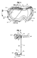
- a goggle 20 which is particularly useful in an outdoor environment, although not limited thereto, includes a plastic flexible frame 22 which surrounds the eye region of a wearer.
- a front lens 24 of plastic material is removably mounted at the forward area of the surrounding frame 22 in order to protect the wearer's eyes.
- a flexible face padding 26 is glued or otherwise affixed to the rear of the frame 22 in order the cushion the frame against the face of the wearer and create a partial seal against the wearer's face.
- An elastic headband strap 28 attaches to both sides of the frame 22 to secure the goggle to the wearer's head or to the back of a helmet, as appropriate.
- the strap 28 will include a buckle adjustment (not illustrated) in order to vary the length of the strap 28 so as to secure the goggle relatively snugly against the face of the wearer.
- the flexible frame 22 includes a top portion 30, a bottom portion 32, and side portions 34 which are injection molded as one piece from a thermoplastic resin such as polycarbonate which results in a molded pliable frame which is relatively stiff as is conventional in vented sports goggles.
- the frame surrounding portions in conjunction with the front lens 24 defines an interior space 36, see Fig. 2, when the goggle is placed against the wearer's face.
- the top portion 30 of the goggle frame is solid and has a generally smooth and planar extent, which can dip in the center.
- This smooth, solid, top surface forms a helmet contacting or mating surface for use when the goggle is worn in conjunction with a helmet.
- the top planar surface will mate with and contact the helmet or helmet padding, in order to form a partial seal between the goggle top where it abuts the helmet.
- the goggle is particularly adapted for use with a helmet, although it is not limited to such use.
- the frame side portions 34 and/or bottom portion 32 have a variety of air vents located therein, for purposes of exiting air flow out of the goggle interior.
- a plurality of forward facing air scoops or air vents 40 are located to directly receive air as the wearer moves relatively in a forward direction.
- This frontal air illustrated by the arrows 42 in Fig. 2, enters the forwardly facing air scoops 40 in large volumes compared to conventional goggles.
- the frontal air 42 is funneled through the inlet vent scoops 40 and into an upper chamber enclosed along its top and side and open downwardly to channel the frontal air into the goggle interior region 36.
- This upper chamber includes means for dispersing the air flow generally downward and with a forward component to improve interior venting of the goggle, but without rapid air flow across the wearer's eyes which could otherwise result if the forward-facing vents 40 directly communicated with the goggle interior.
- the mechanism which redirects and disperses the forward air flow in a controlled manner includes the shape of the upper chamber 44 and, in addition, a permeable foam 50 located in the upper chamber 44.
- This foam 50 is of a porosity and size so as to redirect the air flow with reduced velocity and dispersement into the interior space 36 of the goggle.
- the foam 50 is a thick foam which may take all or substantial portion of the volume of the upper chamber.
- the dimensions of such foam can be approximately 16 mm by 16 mm by the longitudinal length of the upper chamber.
- the foam strip should be in intimate contact with the exit openings of the plurality of air scoops 40. It is formed of an open cell foam having a porosity of 20 to 80 pores per inch (ppi).
- the air flow from the combination of the foam 50 and the upper air chamber moves in a generally downward direction through the interior space 36 and partly against the inside of the front lens 24. This air moves towards a plurality of exit vents 52 located in the frame bottom 32.
- the outlet vents 52 are formed as one or a plurality of apertures in the goggle frame.
- the exit vents 52 are located in the bottom section 32 of the goggle frame so as to draw air from the top of the frame downwardly to exit at the bottom of the frame in the vicinity of the nose region. This serves to disperse moisture-laden air from the wearer's nose and thus assist in reducing fogging within the goggle.
- the exit vents 52 also can be located in the side regions of the frame, in place of or in addition to the exit vents in the bottom section.
- the exit vents 52 are covered with a thin permeable foam strip 54 which can be of 3 mm thickness and having an open cell porosity of 80 ppi.
- the foam 50 associated with the inlet of air is different than the foam 54 associated with the exit of air to better control movement of air through the goggle interior.
- FIG. 1 A goggle of the type illustrated in Figs. 1 and 2 is shown in more detail and various aspects are claimed in a co-pending application of certain of the inventors herein, entitled “Goggle For Sports and Adverse Environments," inventors David T. Robrahn and Robert Youmans, filed on March 5, 1999, and published as US 6138285. Reference should be made to such co-pending application for further explanation about the various mechanical features of the goggle which can be used in conjunction with the present invention.
- the front lens 24 is formed of a plastic material and has a peripheral edge 100 of irregular shape which is inserted in a surrounding groove 84 of the frame for removable retention within the frame.
- the lens edge 100 includes projections for mating engagement with corresponding recesses in the peripheral groove 84.
- the lens projections include side ears 102 on each side of the lens 24, and a central upper tab 104.
- the lens 24 has a recessed nose area 106 which is received within a center nose bridge 68 of the goggle frame so that the interior space 38 surrounds the eyes of the wearer but does not encompass the wearer's nose.
- the recessed nose area 106 has projections 108 which serve as a notch to mate within recessed areas of the peripheral groove 84 to better retain the center portion of the lens within the goggle frame.
- the lens 24 is replaceably mounted within the peripheral groove 84 by manipulating the flexible frame 22 so as to insert the peripheral edge 100 within the surrounding groove 84.
- the various projections 102, 104, 108 extend into mating recesses within the peripheral groove 84 to assist in retaining the replaceable lens 24 within the goggle frame.
- the plastic lens 24 is formed from a thermoplastic resin and may be formed as a spherical lens in order to have the best optical properties or as a cylindrical lens.
- Thermoplastic resins are linear polymers which can be melted and resolidified. Examples of suitable thermoplastic resins for the lens 24 are polycarbonate (PC) as well as the cellulosic family, as will be described.
- the plastic lens 24 is formed out of a polycarbonate (PC) material which is injection molded into a three-dimensional shape having an arcuate curve from top 104 to bottom 106 along its minor axis, and additionally an arcuate curve along its major axis from one side to the other side.
- the lens 24 has a thickness which varies from the center region(s) to its edge 100.
- the lens has a maximum thickness of about 1.5 mm or less, such as 1.3 mm, which tapers to a thickness of 0.9 mm at the peripheral edge 100.
- the radii of curvature from top to bottom and side to side create an overall spherical shape with a varying thickness.
- Such a spherical lens is of very low weight and has good optical properties because it does not create any magnification or distortion.
- the resulting hard plastic lens will maintain its shape and has better optical qualities and impact resistance than a cylindrical plastic lens, albeit at an increased cost of production.
- the replaceable plastic lens 24 can be formed of several cellulosic thermoplastic resins based on cellulose, a complex carbohydrate chemically modified to produce a plastic.
- This cellulosic material is extruded flat with a constant thickness. Then, the lens is stamped out of the flat sheet so as to have the shape illustrated in Fig. 3.
- the use of a cellulosic material produces a flexible lens of low cost and reasonable quality.
- a polycarbonate material which is extruded flat.
- the resulting lens is flat of constant thickness and is flexible.
- Such a cylindrical plastic lens can be produced at relatively low cost and is satisfactory for many applications, although it does not have the superior optical qualities nor impact resistance of a hard lens of polycarbonate which is injection molded in spherical form as previously described.
- the replaceable plastic lens 24, whether produced in the spherical embodiment or in the cylindrical embodiment, is desirably tinted or colored by pigment dyes incorporated into the thermoplastic resin to produce transparent colors to create a high contrast resolution lens.
- the composition of the dyes will vary depending on the composition of the plastic lens 24.
- the resulting lens tint will be referred to at times hereinafter as "HC" for high contrast tint.
- the HC tinted lens desirably has a transmission curve with an undulating or wavy shape which should approximate the sensitivity of the human eye to light of various wavelengths for the intended conditions of use of the goggle, as will be explained.
- the human eye contains photoreceptors which are located in the retina.
- photoreceptors There are two types of photoreceptors, rods which primarily determine night vision and cones which provide high acuity (definition) and color vision in daytime light conditions.
- cones There are three types of cones in the retina of the human eye, each having a different pigment and different absorption curves.
- One set of cones is particularly receptive to blue light in the vicinity of about 400 to 450 nm
- another set of cones is receptive to the absorption of green light around 525 to 575 nm
- the third set of cones is particularly susceptible to red or orange-red light in the vicinity of 550 to 600 nm.
- absorption curves There is substantial overlap of these absorption curves and a broad range of wavelengths are absorbed to some extent by the pigments of all photoreceptors. Both rods and cones function to some degree at all times.
- the responses of rods and cones both contribute to vision at intermediate and other low-level intensities of illumination. Furthermore, the human eye response is not directly related to the peaks of wavelengths per se, but rather to an integration of the spectral curve and relative ratios of intensities of the pigments of the cones and rods. At times only two cones are essentially effective. As light intensity falls, the human eye becomes increasingly sensitive to light of shorter wavelengths. At low light conditions such as twilight the eye is most sensitive to a blue-green light such as 510 nm.
- the HC tint for the lens 24 desirably approximates the response curves for cone photoreceptors in the retina, but with certain modifications to enhance the use of the goggle for certain conditions. Desirably, the goggle lens takes advantage of the shift to shorter wavelengths in low light conditions by modifying the transmission curve of the lens so as to be more efficient in low light conditions such as by enhancing the response to blue light.
- the combination of pigments to be used will vary depending on the thermoplastic resin used for the lens 24.
- Various dyes should be combined so as to approximate to a reasonable extent and at a reasonable cost a spectral curve such that wavelengths less useful to the human retina are reduced in magnitude while wavelengths more useful to the human retina are transmitted in greater quantities.
- the spectral curve is enhanced in the blue light region so as to improve the coupling of transmitted light to the retina for improved resolution in low light conditions.
- the plastic lens 24 is desirably formed of a transparent thermoplastic resin which incorporates dye material so as to tint the lens to transmit an average percentage of light over a wide bandwidth, and to pass selected wavelengths and diminish other wavelengths so as to create a response curve better correlated to the photoreceptors of the eye.
- the lens 24 when used in a ski goggle should reduce the transmission of visible light to the eyes on bright sunny days. It should optimize contrast for overcast conditions.
- the lens should have a high optical quality and a high impact resistance. It should resist fogging. It should be comfortable under prolonged use and be durable. It is also desirable that it absorb as much as possible of ultraviolet (UV) radiation.
- UV ultraviolet
- Plastic lens 24 can be designed as a universal lens adaptable for a wide variety of lighting levels, or can be designed as multiple lenses each designed for a particular level of light. In one preferred form, it was designed as a universal lens for a goggle used in an outdoor environment and this necessitates a compromise for various properties of the lens. If overall light transmission is too high, the eyes will become strained under prolonged use in bright sunlight. If light transmission is too low, contrast will be poor in low light conditions. A desirable range of average light transmission to the eye for such a universal lens is about 25% to 40%. For a single lens, an average light transmission of 35% plus or minus 3% is acceptable. To form a double lens, the same outer lens may be utilized in combination with a clear inner lens, which reduces average transmission about 10%, so the resulting average transmission is about 25% to 27% to the eye.
- HC lens tint Another important factor is to provide a high contrast or "HC" lens tint which will improve contrast resolution in low light conditions.
- HC lens tint which will improve contrast resolution in low light conditions.
- dye material is incorporated into the lens to produce a tint which selectively transmits wavelengths that approximate the absorption wavelengths of the cone photoreceptors including the blue cone receptors.
- Figs. 4 and 5 transmission curves or spectral curves are illustrated for tinted thermoplastic lenses formed of different materials and dye pigments.
- a transmission curve 110 is shown for an HC tinted polycarbonate lens. This can be compared with the transmission curve 112 for a standard tint cellulosics lens, such as a sienna tint of yellow-orange color, illustrated by the dashed lines.
- the transmission curve 130 for an HC tinted cellulosics lens is illustrated.
- the percentage (%) of light transmission through the lens is given for various visible wavelengths of light in nanometers or "nm,” extending from 400 nm to about 700 nm.
- the transmission curve 110 for an HC tinted polycarbonate lens can be produced by incorporating dopants or pigments into the polycarbonate resin prior to injection molding.
- the HC tint may be obtained from a blend of three pigments, namely a white/yellow pigment to give superior filtration in the 400 nm range, a red pigment, and a blue pigment.
- the red and blue pigments have a major function in the filtration of the visible light.
- the quantity of pigments needed depends on the average filtration level that is required, the concentration of the pigments, and the thickness of the lens.
- a ratio suitable for the HC tint seen in the transmission curve 110 is approximately 10 parts for the red pigment compared to one part for the blue pigment.
- the quantities of pigment added into the polycarbonate material are measured in parts per million or ppm. According to the different thickness of the lens in association with the filtration levels, the quantities may vary from less than 10 ppm to more than 200 ppm. As a particular example for a 35% average transmission, the concentration can be 27 ppm for blue pigment and 272 ppm for red pigment. Variations in the pigment levels and tolerances will have an influence on the transmission level, as follows.
- this difference in transmission represents a relative transmission increase of about 19%. This can be achieved by a 15% decrease in the concentration of pigment.
- the variation will depend in part on thickness differences from one lens to another. As another example, if a lens is formed having an average transmission of light in the range of about 25% to 27%, this represents a relative increase of about 8% transmission. This can be achieved by a 5.5% decrease in the concentration of pigment. Again, there will be a variation depending on the thickness differences in the lenses.
- a blend of three pigments as described above to produce the transmission curve 110 seen in the drawings is available as the 61324 tint from Christian Dalloz Sunoptics of Saint-Claude, France, the assignee of certain of the inventors of the present application.
- the properties of the tint pigments are such when incorporated into polycarbonate resin as to produce the transmission curve 110 of Fig. 4 with three peaks 114, 116 and 118 of increased transmission located at approximately 430 nm, 590 nm and 630 nm, respectively. Between peaks 114 and 116 is a valley 120 of reduced transmission which flattens at the area of 510 nm or so. A second valley 122 of reduced transmission is located between peaks 116 and 118 in the vicinity of 610 nm, and a third valley 124 follows the peak 118 at about 680 nm.
- the peak 114 in the vicinity of 430 nm corresponds fairly closely to the peak absorption curve of the blue cone receptors of the human eye. Furthermore, the peak 114 has a light transmission level desirably greater than 20%, such as about 30%. This is followed by a substantial dip to a valley 120 at about a 10% transmission level in the vicinity of 480 to 520 nm. Preferably, the blue response peak 114 is desirably twice to three times the transmission level of the valley 120. While reference is made to the relative heights of the peaks and valleys, it should be understood that the eye will integrate the area under the curve. The peak 114 produces good coupling to the blue cones of the eye and improves contrast in low light conditions.
- the curve 110 of Fig. 4 then has peaks 116 and 118 which each transmit about 60% and are separated by the valley 122 at less than 50% transmission. These peaks and valleys are somewhat transposed from the green and red cone receptors, but nonetheless are reasonably optimized to absorb light wavelengths of more utility to the cone receptors of the human eye.
- the transmission curve for a conventional tinted cellulosics lens is illustrated by the dashed line curve 112 which is for a sienna or yellow-orange tint.
- the curve 112 has a slight rise between 400 nm to 480 nm, but with a less than 10% transmission value, the curve can be considered essentially flat.
- the curve 112 in the vicinity of 500 nm begins a continuous upward slope without pronounced peaks and/or valleys. Such a smooth curve does not couple efficiently to the characteristics of the human eye.
- Table 1 lists the percent (%) transmission of light for wavelengths in nm for the novel HC tint 110 incorporated into a polycarbonate lens and for a standard sienna tint 112 incorporated into a cellulosics lens.
- Wavelength HC Tint Sienna Tint 400 0.0% 8.8% 410 8.1% 8.2% 420 29.1% 6.6% 430 31.6% 4.9% 440 25.5% 3.3% 450 20.7% 2.2% 460 16.1% 1.5% 470 12.8% 0.8% 480 11.3% 0.6% 490 10.6% 0.6% 500 10.6% 0.6% 510 10.4% 1.1% 520 12.4% 2.8% 530 17.5% 7.1% 540 21.2% 12.8% 550 24.5% 18.9% 560 31.1% 26.5% 570 41.4% 35.3% 580 53.1% 44.1% 590 64.4% 51.4% 600 60.9% 56.5% 610 48.3% 59.5% 620 54.8% 61.6% 630 60.7% 62.8% 640 56.1% 63.7% 650 51.3%
- the transmission curve 130 represents one embodiment for a cellulosics lens 24.
- This lens was produced by attempting to color match a tinted polycarbonate lens having the transmission curve 110 of Fig. 4.
- the difference in the absorption bands between curves 110 and 130 are attributed in part to the use of a cellulosics lens rather than a polycarbonate lens as well as different dye pigments.
- the HC tint for a cellulosics lens is available as ZO705 orange pigments from Polymer Extruded Products, Inc. of Newark, New Jersey, and the pigments were produced by Eastman.
- the resulting curve 130 is less satisfactory than the curve 110 of Fig. 4, but it does produce a better coupling to the cone receptors of the retina than prior art tints such as 112 incorporated in a cellulosics lens.
- the HC tint 130 produces three peaks 132, 134 and 136.
- the first peak 132 has a maximum transmission of about 35% located in the blue color range between 410 to 430 nm.
- the blue peak 132 then sharply drops to a valley 140 having transmission of 12% to 15% or so. Desirably there is a two to three times difference in transmission level between the first valley 140 and the first peak 132.
- the transmission curve 130 then rises to a plateau 134 of near 60% transmission in the area of 590 to 610 nm.
- the plastic lens 24 is desirably formed from a polycarbonate (PC) material which is injection molded to create a hard lens blank having a varying thickness.
- PC polycarbonate
- the lens blank may have multiple radii to reduce distortion. Examples of spherical lens shapes and a process of manufacturing lens blanks are illustrated in U.S. Patent No. 1,741,536 to Rayton entitled “Goggles,” issued December 31, 1929, U.S. Patent No. 4,271,538 to Montesi et al., entitled “Safety Spectacles,” issued June 9, 1981, and U.S. Patent No.
- the blank may be stamped or cut with a peripheral edge shape as illustrated in Fig. 3 by a lens manufacturer in order to produce a replaceable lens member usable with a goggle.
- the lens blank can be supplied to a goggle manufacturer who can then die cut the lens blank into the appropriate shape to form the replaceable lens member for the goggle.
- the resulting PC lens member will have a high impact resistance as is desirable for sports goggles and safety goggles.
- the PC lens may be treated with a coating in order to improve scratch resistance.
- the plastic lens 24 is preferably made out of the cellulose family.
- the lens can be formed from cellulose acetate (CA), cellulose acetobutyrate (CAB), or cellulose acetopropionate (CAP).
- CA cellulose acetate
- CAB cellulose acetobutyrate
- CAP cellulose acetopropionate
- these cellulosics are compounded with plasticizers and are then extruded into a flat sheet of constant thickness.
- the optical quality of the flat sheet can be improved by placing the cellulosic sheet between chemically polished metal sheets and then pressing the laminate at high pressure and temperature, in a process known as press polishing. This improves the optical clarity of the sheet and reduces surface defects that will impair vision.
- the resulting cellulosic lens member can then be cut or stamped so as to have the peripheral edge shape of Fig. 3 in order to form a replaceable lens for a goggle.
- the impact resistance will vary with the amount of plasticizer added for processing.
- the lens 24 when formed of CAP will have the highest impact resistance for a cellulosics lens, with CAP being a close second, and CA being considerably below CAP.
- the plastic lens 24 should resist fogging caused by an increase in relative humidity in the interior space 36.
- the venting of the goggle interior through the inlet vents 40 and outlet vents 52 assists to reduce the relative humidity.
- the lens 24 can be surface treated with an anti-fogging coating to cause water on the interior side of the lens to bead or form a film.
- the plastic lens 24 when formed of cellulosic material is desirably treated by immersion into a solution that chemically treats both surfaces or at least the inner surface adjacent interior space 36. This treatment is done in sheet form prior to forming. The result is a surface that initially absorbs moisture until saturation, and then causes additional moisture to form as a film of water rather than beads.
- an anti-fogging coating can be applied to one or both surfaces by dipping the lens into a solution. The result is a surface which tends to form beads of water on the treated side of the lens.
- the lens 24 can be of double lens construction, often referred to as a thermal lens.
- the outer lens can be a thin, injection molded, spherical lens of polycarbonate material which is hard-coated on both sides.
- the polycarbonate material is colored with the HC tint pigments described previously.
- the inner lens can be formed of clear cellulosic material such as CAP having for example a 0.025 (approximately 0.635 mm) inch thickness with an anti-fog treatment on one or both sides. To ensure preciseness in curvature, it should be thermoformed to match the inner radius of the outer PC lens.
- the inner and outer lens can be separated by a gasket spacer, such as a 0.125 (approximately 3.175 mm) inch thick foam with adhesive on both sides around the entire peripheral edge.
- the plastic lens 24 absorb or block as much ultraviolet (UV) radiation as possible.
- UV radiation ultraviolet radiation
- the lens filter as much as possible of UV rays from 100 to 400 nm.
- the lens can have a conventional dye added in order to create a tint which will filter out most ultraviolet wavelengths up to about 380 nm.
- the embodiments disclose a goggle which overcomes certain of the problems and disadvantages of prior goggles. Many of its features have utility when a goggle is worn in conjunction with a helmet or protective headgear, although the goggle is not limited to use with a helmet or headgear. Other features overcome problems associated with goggles intended to be used in a high speed sport, as well as problems associated with the outdoor environment which is more prone to a wide variety of light and atmospheric conditions, including lack of contrast between adjacent surfaces in certain low light adverse conditions.
- the goggle may have a removable plastic lens which is tinted in a manner to improve contrast resolution for a wide variety of light levels and light characteristics including certain adverse conditions.
- the tint is adapted to the plastic materials usable in goggle lenses to provide a goggle having improved visual performance and anti-fogging characteristics.
- the tint creates a transmission curve characterized by peaks and valleys along the visible wavelength spectrum which conforms to certain characteristics of the human eye to improve contrast in a plastic lens.
- Such a plastic lens is particularly useful when it is removable and can be replaced as necessary.
- the goggle may be formed of a flexible frame which surrounds the wearer's eyes and is used in conjunction with a removable plastic lens. Such a goggle can be adapted to an outdoor environment having adverse condition.
- a goggle frame may be vented and include vent openings covered by porous foam for exchanging air within the goggle interior in a manner which reduces fogging or condensation on the interior of a plastic tinted lens having various coatings for anti-fogging purposes.
- vented goggles are particularly adaptable to a sports environment such as winter sports or motorcycling, but also have aoplicability to a safety goggle.
Landscapes
- Health & Medical Sciences (AREA)
- Ophthalmology & Optometry (AREA)
- Physics & Mathematics (AREA)
- General Health & Medical Sciences (AREA)
- Heart & Thoracic Surgery (AREA)
- Engineering & Computer Science (AREA)
- Life Sciences & Earth Sciences (AREA)
- Animal Behavior & Ethology (AREA)
- Biomedical Technology (AREA)
- Public Health (AREA)
- Veterinary Medicine (AREA)
- Vascular Medicine (AREA)
- Optics & Photonics (AREA)
- Spectroscopy & Molecular Physics (AREA)
- General Physics & Mathematics (AREA)
- Eyeglasses (AREA)
- Compositions Of Macromolecular Compounds (AREA)
- Respiratory Apparatuses And Protective Means (AREA)
Abstract
Description
| Wavelength | HC | Sienna Tint | |
| 400 | 0.0% | 8.8% | |
| 410 | 8.1% | 8.2% | |
| 420 | 29.1% | 6.6% | |
| 430 | 31.6% | 4.9% | |
| 440 | 25.5% | 3.3% | |
| 450 | 20.7% | 2.2% | |
| 460 | 16.1% | 1.5% | |
| 470 | 12.8% | 0.8% | |
| 480 | 11.3% | 0.6% | |
| 490 | 10.6% | 0.6% | |
| 500 | 10.6% | 0.6% | |
| 510 | 10.4% | 1.1% | |
| 520 | 12.4% | 2.8% | |
| 530 | 17.5% | 7.1% | |
| 540 | 21.2% | 12.8% | |
| 550 | 24.5% | 18.9% | |
| 560 | 31.1% | 26.5% | |
| 570 | 41.4% | 35.3% | |
| 580 | 53.1% | 44.1% | |
| 590 | 64.4% | 51.4% | |
| 600 | 60.9% | 56.5% | |
| 610 | 48.3% | 59.5% | |
| 620 | 54.8% | 61.6% | |
| 630 | 60.7% | 62.8% | |
| 640 | 56.1% | 63.7% | |
| 650 | 51.3% | 64.2% | |
| 660 | 35.7% | 64.7% | |
| 670 | 6.7% | 65.1% | |
| 680 | 4.6% | 65.5% | |
| 690 | 26.8% | 65.7% | |
| 700 | 64.2% | 66.1% |
Claims (14)
- A goggle (20) comprising:a frame (22) having sections (30,32,34) for surrounding a wearer's face including a frame mounting section (84),a plastic lens (24) formed of a thermoplastic resin and mountable in the frame mounting section in spaced relation in front of the wearer's face to define an interior space (36),the thermoplastic resin incorporating dye material to tint the plastic lens to transmit variable amounts of light over a range of visible wavelengths between 400 nm and 700 nm, characterized in that the tinted plastic lens has a transmission curve (HC) with at least a first peak (114; 132) and a second peak (116; 134) of increased transmission over said visible wavelengths range and a valley (120;140) of reduced transmission of more than 10% transmission decrease between the first and second peaks to improve contrast for a wearer of the goggle, wherein said first peak is located substantially in the range of 400 to 450 nm, which corresponds to the blue absorption band for cone photoreceptors in a human eye retina.
- The goggle of claim 1, wherein the thermoplastic resin is comprised of polycarbonate material which is injection molded to form the plastic lens with an average transmission of visible light in the range of about 25% to 40%.
- The goggle of claim 2, wherein the polycarbonate material is injection molded into a spherical lens having a varying thickness from a center towards its edge.
- The goggle of claim 1, wherein a thermoplastic resin is comprised of the cellulosic material which is extruded into a sheet which forms the plastic lens with an average transmision of visible light in the range of about 25% to 40%.
- The goggle of claim 4, wherein the cellulosic material is extruded into a flat sheet of constant thickness, the frame mounting section having a curved shape, and the plastic lens being mountable therein to create a cylindrical lens of constant thickness.
- The goggle of claim 1, wherein said first peak (114, 132) has greater than 20% transmission.
- The goggle of claim 1, wherein the lens is a single lens having an average transmission of light in the range of about 32% to 38%.
- The goggle of claim 1, wherein the lens is a double lens having an average transmission of light in the range of about 25% to 27%.
- The goggle of claim 1, wherein said valley between the first and second peaks has a 15% transmission or less for light in the second range of wavelengths adjacent said blue absorption band.
- The goggle of claim 1, wherein the second peak is located in the vicinity of the green absorption band for cone receptors in a human eye retina and has a greater than 50% transmission located in the vicinity of 590 nm.
- The goggle of claim 1, a third peak (118) with a second valley (122) located between the second peak and the third peak and a third valley (124) located after said third peak, wherein the first valley, second valley and third valley each have more than a 10% transmission decrease from the preceding peak.
- The goggle of claim 11, wherein the third peak has a greater than 50% transmission and is located in the vicinity of 630 nm.
- The goggle of claim 11, wherein the third valley has more than a 40% transmission decrease from said third peak.
- The goggle of claim 1 wherein the plastic lens (24) has an average transmission of light in the range of about 25% to 40%.
Applications Claiming Priority (3)
| Application Number | Priority Date | Filing Date | Title |
|---|---|---|---|
| US291711 | 1981-08-10 | ||
| US09/291,711 US6138286A (en) | 1999-04-14 | 1999-04-14 | Goggle having a tinted plastic lens |
| PCT/US2000/009399 WO2000061043A1 (en) | 1999-04-14 | 2000-04-07 | Goggle having a tinted plastic lens |
Publications (3)
| Publication Number | Publication Date |
|---|---|
| EP1171064A1 EP1171064A1 (en) | 2002-01-16 |
| EP1171064A4 EP1171064A4 (en) | 2002-10-16 |
| EP1171064B1 true EP1171064B1 (en) | 2004-09-15 |
Family
ID=23121498
Family Applications (1)
| Application Number | Title | Priority Date | Filing Date |
|---|---|---|---|
| EP00921917A Expired - Lifetime EP1171064B1 (en) | 1999-04-14 | 2000-04-07 | Goggle having a tinted plastic lens |
Country Status (7)
| Country | Link |
|---|---|
| US (1) | US6138286A (en) |
| EP (1) | EP1171064B1 (en) |
| JP (1) | JP2002540895A (en) |
| AT (1) | ATE275905T1 (en) |
| AU (1) | AU4217500A (en) |
| DE (1) | DE60013795T2 (en) |
| WO (1) | WO2000061043A1 (en) |
Cited By (1)
| Publication number | Priority date | Publication date | Assignee | Title |
|---|---|---|---|---|
| EP3496684A1 (en) * | 2016-08-12 | 2019-06-19 | 100% Speedlab, LLC | Multi-thickness goggle lenses |
Families Citing this family (77)
| Publication number | Priority date | Publication date | Assignee | Title |
|---|---|---|---|---|
| US6138285A (en) * | 1999-03-05 | 2000-10-31 | Scott Usa, Inc. | Goggle for sports and adverse environments |
| JP3481513B2 (en) * | 1999-07-30 | 2003-12-22 | 株式会社タバタ | Swimming goggles |
| JP4378584B2 (en) * | 2000-02-22 | 2009-12-09 | 山本光学株式会社 | goggles |
| US7077985B2 (en) | 2000-05-30 | 2006-07-18 | Vision-Ease Lens | Injection molding of lens |
| US6732383B2 (en) | 2001-12-03 | 2004-05-11 | The Burton Corporation | Goggle with side arm for wearing with a helmet |
| US6615409B2 (en) | 2001-12-11 | 2003-09-09 | Scott Usa, Inc. | Tinted plastic lens for eye protecting devices |
| US7036932B2 (en) * | 2002-10-04 | 2006-05-02 | Vision-Ease Lens | Laminated functional wafer for plastic optical elements |
| USD503736S1 (en) | 2003-01-03 | 2005-04-05 | The Burton Corporation | Goggle frame |
| BR0300536A (en) * | 2003-03-07 | 2004-11-03 | Eduardo De Queiroz Scherer | Multifunctional glasses in three ways of use, in one |
| US7020901B2 (en) * | 2003-07-21 | 2006-04-04 | Brhel Joseph A | Eye and ear protection apparatus |
| US7858001B2 (en) | 2003-09-09 | 2010-12-28 | Insight Equity A.P.X., L.P. | Photochromic lens |
| WO2005023529A2 (en) | 2003-09-09 | 2005-03-17 | Vision-Ease Lens, Inc. | Photochromic polyurethane laminate |
| USD503422S1 (en) | 2003-10-29 | 2005-03-29 | Bacou-Dalloz Eye & Face Protection, Inc. | Silicone goggle |
| JP2005261606A (en) * | 2004-03-18 | 2005-09-29 | Ricoh Microelectronics Co Ltd | Guard against ultraviolet laser, and guard set against ultraviolet laser |
| US7126732B2 (en) * | 2004-07-29 | 2006-10-24 | Smith Sport Optics, Inc. | Lens structures, goggles employing same, methods of forming same, and machine programmed for forming same |
| US20060059608A1 (en) * | 2004-08-26 | 2006-03-23 | The Burton Corporation | Ventilated eyewear |
| US7699479B2 (en) * | 2004-10-06 | 2010-04-20 | Mirror Lite | Teardrop shaped vehicular mirror |
| US8777428B2 (en) | 2004-10-06 | 2014-07-15 | Rosco, Inc. | Teardrop shaped vehicular mirror |
| AU303084S (en) * | 2005-01-10 | 2005-09-01 | Silhouette Int Schmied A G | Sports glasses |
| US8002935B2 (en) | 2005-03-04 | 2011-08-23 | Insight Equity A.P.X., L.P. | Forming method for polymeric laminated wafers comprising different film materials |
| WO2007080455A2 (en) | 2005-05-17 | 2007-07-19 | Revision Eyewear, Inc. | Protective eyewear including auxiliary lenses |
| ES2548242T3 (en) * | 2006-01-20 | 2015-10-15 | Smith Optics, Inc. | Thermal protective glasses lens set with outdoor ventilation chamber |
| US8800066B2 (en) * | 2006-08-04 | 2014-08-12 | I.E. Manufacturing Llc | Fog-resistant goggles |
| USD581964S1 (en) | 2006-08-04 | 2008-12-02 | I. E. Manufacturing Llc. | Fog-resistant goggles |
| USD559299S1 (en) * | 2006-12-18 | 2008-01-08 | Safilo Societa Azionaria Fabbrica Italiana Lavorazione Occhiali S.P.A. | Goggles |
| NL1033103C2 (en) * | 2006-12-21 | 2008-06-24 | Hd Inspiration Holding B V | Visor with UV sensitive material. |
| US7630128B2 (en) * | 2007-02-02 | 2009-12-08 | Sperian Eye & Face Protection Inc. a Delaware Corporation | Optical filter panel having a narrow-width selective-wavelength attenuation and high visible light transmission |
| FR2923917B1 (en) * | 2007-11-16 | 2010-11-26 | Christian Dalloz Sunoptics | NOVEL TRANSPARENT OPTICAL SUBSTRATE, ITS OBTAINING METHOD AND ITS APPLICATION AS EYE |
| USD582967S1 (en) | 2007-12-04 | 2008-12-16 | Silhouette International Schmied Ag | Sunglasses |
| US8356895B2 (en) * | 2008-01-17 | 2013-01-22 | Zeal Optics, Inc. | All weather sport goggle |
| US8636786B2 (en) * | 2008-05-16 | 2014-01-28 | Seth A. Biser | Thermal compress system and methods of using the same |
| US8784391B1 (en) | 2010-11-18 | 2014-07-22 | Seth Biser | Therapeutic compress system and methods of use |
| US11076983B2 (en) | 2008-05-16 | 2021-08-03 | Seth A. Biser | Thermal eye compress systems and methods of use |
| US20090300830A1 (en) * | 2008-06-05 | 2009-12-10 | Mage Jerome J M | Goggle with removable lens |
| US20090300812A1 (en) * | 2008-06-10 | 2009-12-10 | Qbas Co., Ltd. | Lens Assembly for a Diving Mask |
| US20100149483A1 (en) * | 2008-12-12 | 2010-06-17 | Chiavetta Iii Stephen V | Optical Filter for Selectively Blocking Light |
| JP5152597B2 (en) * | 2009-11-30 | 2013-02-27 | 山本光学株式会社 | Optical structure for the eye |
| USD616915S1 (en) | 2009-12-02 | 2010-06-01 | Sperian Eye & Face Protection, Inc. | Safety goggle |
| US8770749B2 (en) | 2010-04-15 | 2014-07-08 | Oakley, Inc. | Eyewear with chroma enhancement |
| FR2959121B1 (en) * | 2010-04-22 | 2013-01-18 | Salomon Sas | PROTECTIVE MASK FOR THE PRACTICE OF OUTDOOR SPORTS. |
| US9138026B2 (en) | 2011-09-15 | 2015-09-22 | Spy Optic Inc. | Facial cushion |
| CA3090848A1 (en) | 2011-10-20 | 2013-05-16 | Oakley, Inc. | Eyewear with chroma enhancement |
| WO2013078442A1 (en) * | 2011-11-25 | 2013-05-30 | David Mcculloch | Modular anti-fog goggle system |
| US20140053308A1 (en) * | 2012-01-30 | 2014-02-27 | Mubeen A. Cutchi | Face Shield Attachment for Winter Jacket Hoods |
| USD714378S1 (en) | 2012-04-04 | 2014-09-30 | Spy Optic Inc. | Sports goggle |
| USD669113S1 (en) | 2012-04-10 | 2012-10-16 | Spy Optic Inc. | Sports goggle |
| WO2013169987A1 (en) | 2012-05-10 | 2013-11-14 | Oakley, Inc. | Eyewear with laminated functional layers |
| US9720255B2 (en) | 2013-11-06 | 2017-08-01 | Spy Optic Inc. | Apparatus for removably attaching outer lenses to goggles |
| US9575335B1 (en) | 2014-01-10 | 2017-02-21 | Oakley, Inc. | Eyewear with chroma enhancement for specific activities |
| US10871661B2 (en) | 2014-05-23 | 2020-12-22 | Oakley, Inc. | Eyewear and lenses with multiple molded lens components |
| TWD165997S (en) * | 2014-07-29 | 2015-02-11 | 羅一國際股份有限公司 | Glasses base part |
| TWM490335U (en) * | 2014-08-19 | 2014-11-21 | Qbas Co Ltd | Waterproof goggle |
| USD755279S1 (en) * | 2014-10-09 | 2016-05-03 | Swivel Vision Sports LLC | Sports training goggles |
| US9895266B2 (en) | 2014-10-16 | 2018-02-20 | Spy Optic Inc. | Goggle lens changing system |
| CN207704150U (en) | 2014-11-13 | 2018-08-07 | 奥克利有限公司 | Variable light attenuating eyewear with color enhancement |
| US9905022B1 (en) | 2015-01-16 | 2018-02-27 | Oakley, Inc. | Electronic display for demonstrating eyewear functionality |
| WO2017062813A1 (en) | 2015-10-09 | 2017-04-13 | Oakley, Inc. | Headworn supports with passive venting and removable lens |
| USD800825S1 (en) | 2015-11-06 | 2017-10-24 | H&H Sports Protection Srl | Goggles |
| US10571714B2 (en) | 2017-02-15 | 2020-02-25 | Advanced Eye Protection IP Holding | Snap-fit features in eyewear |
| US11234867B2 (en) | 2017-08-01 | 2022-02-01 | Spy Optic Inc. | Goggle lens changing system |
| US12124116B2 (en) * | 2017-10-20 | 2024-10-22 | Luxottica S.R.L. | Eyewear with variable transmission lens |
| US11112622B2 (en) | 2018-02-01 | 2021-09-07 | Luxottica S.R.L. | Eyewear and lenses with multiple molded lens components |
| CA3132037A1 (en) | 2018-03-02 | 2019-09-06 | 100% Speedlab, Llc | Goggle having a latchable lens |
| US11833084B2 (en) | 2018-03-02 | 2023-12-05 | 100% Speedlab, Llc | Goggle systems and methods |
| USD884913S1 (en) * | 2018-06-28 | 2020-05-19 | Shenzhen Breo Technology Co., Ltd. | Eye massager |
| NO348781B1 (en) | 2018-12-12 | 2025-06-02 | Active Brands As | Optical filter for snow conditions |
| CN111319209A (en) * | 2018-12-14 | 2020-06-23 | 张明月 | Goggles lens and processing technology thereof |
| USD915499S1 (en) | 2019-04-12 | 2021-04-06 | 100% Speedlab, Llc | Goggles |
| CN110262075A (en) * | 2019-04-29 | 2019-09-20 | 济宁韩瑞眼镜有限公司 | One kind is ridden glasses |
| JP7361302B2 (en) * | 2019-10-30 | 2023-10-16 | パナソニックIpマネジメント株式会社 | Optical filters, color vision correction lenses, and optical components for color vision correction |
| US12429714B2 (en) | 2019-11-26 | 2025-09-30 | Oakley, Inc. | High transmittance eyewear with chroma enhancement |
| US11389330B2 (en) | 2019-12-31 | 2022-07-19 | Spy Optic Inc. | Magnetic goggle lens changing system |
| USD1089372S1 (en) * | 2021-07-30 | 2025-08-19 | 100% Speedlab, Llc | Shield for goggles |
| US11630328B1 (en) * | 2022-01-26 | 2023-04-18 | Tara L. Jennis | Sunglasses with clear bifocals |
| USD984520S1 (en) * | 2023-01-18 | 2023-04-25 | Shenzhen Leshuo Technology Co., Ltd | Goggles |
| EP4588535A1 (en) * | 2024-01-18 | 2025-07-23 | Cressi-Sub S.p.A. | Swimming goggles |
| WO2025175336A1 (en) * | 2024-02-21 | 2025-08-28 | Minimis Technologies Proprietary Limited | Eyewear defogging ventilation system |
Family Cites Families (25)
| Publication number | Priority date | Publication date | Assignee | Title |
|---|---|---|---|---|
| US1741536A (en) * | 1927-05-21 | 1929-12-31 | Bausch & Lomb | Goggles |
| GB1021466A (en) * | 1963-11-14 | 1966-03-02 | Safety Products Ltd | Improvements in or relating to goggles for industrial, sporting or other purposes |
| US4152332A (en) * | 1966-09-02 | 1979-05-01 | Polaroid Corporation | Metal complexes of certain hetero-ethene dithiols |
| FR1576414A (en) * | 1968-04-10 | 1969-08-01 | ||
| US3718937A (en) * | 1969-12-29 | 1973-03-06 | Smith R Co | Double lens goggle and method of manufacture |
| US4043637A (en) * | 1973-06-15 | 1977-08-23 | American Optical Corporation | Photochromic light valve |
| US3945044A (en) * | 1974-03-07 | 1976-03-23 | Scott Usa | Goggle and accessories therefor |
| US4271538A (en) * | 1980-03-24 | 1981-06-09 | Norton Company | Safety spectacles |
| US4952046A (en) * | 1982-02-26 | 1990-08-28 | Stephens James B | Optical lenses with selective transmissivity functions |
| US4653124A (en) * | 1985-07-16 | 1987-03-31 | Scott Usa | Face mask having an air duct connectable to a goggle |
| US5177509A (en) * | 1987-02-26 | 1993-01-05 | Suntiger, Inc. | Ultraviolet radiation and blue light blocking polarizing lens |
| GB8921993D0 (en) * | 1989-09-29 | 1989-11-15 | Pilkington Visioncare Holdings | Colour enhancing lens |
| US5408278A (en) * | 1990-11-23 | 1995-04-18 | Christman; Ernest H. | Method and device for enhancing visual and color perception |
| US5363512A (en) * | 1992-01-30 | 1994-11-15 | Smith Sport Optics, Inc. | Protective goggle and lens with adjustable ventilation |
| US5546611A (en) * | 1992-08-21 | 1996-08-20 | Lathrop; Kim N. | High performance swim goggle structure |
| US5341516A (en) * | 1992-12-22 | 1994-08-30 | Eric Keim | Goggle support system |
| JPH06265830A (en) * | 1993-03-11 | 1994-09-22 | Nikon Corp | Colored plastic lens |
| US5366940A (en) * | 1994-01-28 | 1994-11-22 | Bausch & Lomb Incorporated | Transparent, fixed tint glass lenses |
| US5922246A (en) * | 1995-07-28 | 1999-07-13 | Kyowa Hakko Kogyo Co., Ltd | Eyeglass lens and molded material of synthetic resin having transmittance minimum no greater than 25% at 550-585 nm |
| FR2740231B1 (en) * | 1995-10-20 | 1998-03-06 | Christian Dalloz Sa | DRAFT FOR NON-CORRECTOR EYEPIECE |
| AUPN685495A0 (en) * | 1995-11-28 | 1995-12-21 | Sola International Holdings Ltd | Light transmitting articles with colour enhancing properties |
| CA2249584C (en) * | 1996-03-21 | 2007-03-27 | Sola International Holdings Ltd. | Improved single vision lenses |
| JP3357803B2 (en) * | 1996-10-30 | 2002-12-16 | タレックス光学工業株式会社 | Polarizing film for glasses and polarizing glasses |
| US5975695A (en) * | 1997-09-10 | 1999-11-02 | Intercast Europe S.P.A. | Optical element for use in eye-protecting devices |
| JP3130510B2 (en) * | 1998-12-07 | 2001-01-31 | 株式会社ウインテックインターナショナルジャパン | Method of manufacturing polarized lens for sunglasses and apparatus for manufacturing the same |
-
1999
- 1999-04-14 US US09/291,711 patent/US6138286A/en not_active Expired - Lifetime
-
2000
- 2000-04-07 WO PCT/US2000/009399 patent/WO2000061043A1/en not_active Ceased
- 2000-04-07 JP JP2000610381A patent/JP2002540895A/en active Pending
- 2000-04-07 AT AT00921917T patent/ATE275905T1/en active
- 2000-04-07 AU AU42175/00A patent/AU4217500A/en not_active Abandoned
- 2000-04-07 EP EP00921917A patent/EP1171064B1/en not_active Expired - Lifetime
- 2000-04-07 DE DE60013795T patent/DE60013795T2/en not_active Expired - Lifetime
Cited By (1)
| Publication number | Priority date | Publication date | Assignee | Title |
|---|---|---|---|---|
| EP3496684A1 (en) * | 2016-08-12 | 2019-06-19 | 100% Speedlab, LLC | Multi-thickness goggle lenses |
Also Published As
| Publication number | Publication date |
|---|---|
| WO2000061043A1 (en) | 2000-10-19 |
| DE60013795T2 (en) | 2005-09-29 |
| AU4217500A (en) | 2000-11-14 |
| DE60013795D1 (en) | 2004-10-21 |
| EP1171064A1 (en) | 2002-01-16 |
| EP1171064A4 (en) | 2002-10-16 |
| JP2002540895A (en) | 2002-12-03 |
| ATE275905T1 (en) | 2004-10-15 |
| US6138286A (en) | 2000-10-31 |
Similar Documents
| Publication | Publication Date | Title |
|---|---|---|
| US6138286A (en) | Goggle having a tinted plastic lens | |
| US6615409B2 (en) | Tinted plastic lens for eye protecting devices | |
| US6604824B2 (en) | Polarized lens with oxide additive | |
| EP1636634B1 (en) | Eyewear lens having selective spectral response | |
| US7036927B2 (en) | Face foam free protective eyewear with inner liner and vent | |
| CN216696913U (en) | Eyewear and lenses with multiple molded lens components | |
| US10642071B2 (en) | Tinted polarized lenses having selective frequency filtering | |
| US10871661B2 (en) | Eyewear and lenses with multiple molded lens components | |
| US6334680B1 (en) | Polarized lens with oxide additive | |
| EP3698207B1 (en) | Eyewear with variable transmission lens | |
| WO2015179538A1 (en) | Eyewear and lenses with multiple molded lens components | |
| US7775659B2 (en) | Sunglass lens | |
| JP2023551988A (en) | Eye protection mask for practicing winter sports | |
| WO2017099800A1 (en) | Eyewear with reflective filters | |
| US20240369857A1 (en) | Ophthalmic articles | |
| US6416178B1 (en) | Color translucent eyewear lenses applied with antireflective (AR) coatings | |
| JP3718185B2 (en) | Eyeglass lenses | |
| TW202526451A (en) | Infrared-filtering thermal-isolative optical lens device and method thereof for whole-visible-spectrum enhancement | |
| US20210157170A1 (en) | High transmittance eyewear with chroma enhancement | |
| AU2004251323C1 (en) | Eyewear lens having selective spectral response | |
| CN120178541A (en) | A ski goggles convenient for ventilation | |
| MXPA05013218A (en) | Eyewear lens having selective spectral response | |
| JPH08248361A (en) | Sunglasses suppressing translucency |
Legal Events
| Date | Code | Title | Description |
|---|---|---|---|
| PUAI | Public reference made under article 153(3) epc to a published international application that has entered the european phase |
Free format text: ORIGINAL CODE: 0009012 |
|
| 17P | Request for examination filed |
Effective date: 20011112 |
|
| AK | Designated contracting states |
Kind code of ref document: A1 Designated state(s): AT BE CH CY DE DK ES FI FR GB GR IE IT LI LU MC NL PT SE |
|
| AX | Request for extension of the european patent |
Free format text: AL;LT;LV;MK;RO;SI |
|
| A4 | Supplementary search report drawn up and despatched |
Effective date: 20020902 |
|
| AK | Designated contracting states |
Kind code of ref document: A4 Designated state(s): AT BE CH CY DE DK ES FI FR GB GR IE IT LI LU MC NL PT SE |
|
| 17Q | First examination report despatched |
Effective date: 20030604 |
|
| GRAP | Despatch of communication of intention to grant a patent |
Free format text: ORIGINAL CODE: EPIDOSNIGR1 |
|
| GRAS | Grant fee paid |
Free format text: ORIGINAL CODE: EPIDOSNIGR3 |
|
| GRAA | (expected) grant |
Free format text: ORIGINAL CODE: 0009210 |
|
| AK | Designated contracting states |
Kind code of ref document: B1 Designated state(s): AT BE CH CY DE DK ES FI FR GB GR IE IT LI LU MC NL PT SE |
|
| PG25 | Lapsed in a contracting state [announced via postgrant information from national office to epo] |
Ref country code: NL Free format text: LAPSE BECAUSE OF FAILURE TO SUBMIT A TRANSLATION OF THE DESCRIPTION OR TO PAY THE FEE WITHIN THE PRESCRIBED TIME-LIMIT Effective date: 20040915 Ref country code: BE Free format text: LAPSE BECAUSE OF FAILURE TO SUBMIT A TRANSLATION OF THE DESCRIPTION OR TO PAY THE FEE WITHIN THE PRESCRIBED TIME-LIMIT Effective date: 20040915 Ref country code: FI Free format text: LAPSE BECAUSE OF FAILURE TO SUBMIT A TRANSLATION OF THE DESCRIPTION OR TO PAY THE FEE WITHIN THE PRESCRIBED TIME-LIMIT Effective date: 20040915 |
|
| REG | Reference to a national code |
Ref country code: GB Ref legal event code: FG4D Ref country code: CH Ref legal event code: EP |
|
| REG | Reference to a national code |
Ref country code: IE Ref legal event code: FG4D |
|
| REF | Corresponds to: |
Ref document number: 60013795 Country of ref document: DE Date of ref document: 20041021 Kind code of ref document: P |
|
| PG25 | Lapsed in a contracting state [announced via postgrant information from national office to epo] |
Ref country code: GR Free format text: LAPSE BECAUSE OF FAILURE TO SUBMIT A TRANSLATION OF THE DESCRIPTION OR TO PAY THE FEE WITHIN THE PRESCRIBED TIME-LIMIT Effective date: 20041215 Ref country code: DK Free format text: LAPSE BECAUSE OF FAILURE TO SUBMIT A TRANSLATION OF THE DESCRIPTION OR TO PAY THE FEE WITHIN THE PRESCRIBED TIME-LIMIT Effective date: 20041215 |
|
| REG | Reference to a national code |
Ref country code: CH Ref legal event code: NV Representative=s name: KIRKER & CIE SA |
|
| PG25 | Lapsed in a contracting state [announced via postgrant information from national office to epo] |
Ref country code: ES Free format text: LAPSE BECAUSE OF FAILURE TO SUBMIT A TRANSLATION OF THE DESCRIPTION OR TO PAY THE FEE WITHIN THE PRESCRIBED TIME-LIMIT Effective date: 20041226 |
|
| REG | Reference to a national code |
Ref country code: SE Ref legal event code: TRGR |
|
| LTIE | Lt: invalidation of european patent or patent extension |
Effective date: 20040915 |
|
| NLV1 | Nl: lapsed or annulled due to failure to fulfill the requirements of art. 29p and 29m of the patents act | ||
| PG25 | Lapsed in a contracting state [announced via postgrant information from national office to epo] |
Ref country code: LU Free format text: LAPSE BECAUSE OF NON-PAYMENT OF DUE FEES Effective date: 20050407 Ref country code: CY Free format text: LAPSE BECAUSE OF FAILURE TO SUBMIT A TRANSLATION OF THE DESCRIPTION OR TO PAY THE FEE WITHIN THE PRESCRIBED TIME-LIMIT Effective date: 20050407 Ref country code: IE Free format text: LAPSE BECAUSE OF NON-PAYMENT OF DUE FEES Effective date: 20050407 |
|
| PG25 | Lapsed in a contracting state [announced via postgrant information from national office to epo] |
Ref country code: MC Free format text: LAPSE BECAUSE OF NON-PAYMENT OF DUE FEES Effective date: 20050430 |
|
| PLBE | No opposition filed within time limit |
Free format text: ORIGINAL CODE: 0009261 |
|
| STAA | Information on the status of an ep patent application or granted ep patent |
Free format text: STATUS: NO OPPOSITION FILED WITHIN TIME LIMIT |
|
| ET | Fr: translation filed | ||
| 26N | No opposition filed |
Effective date: 20050616 |
|
| PG25 | Lapsed in a contracting state [announced via postgrant information from national office to epo] |
Ref country code: PT Free format text: LAPSE BECAUSE OF NON-PAYMENT OF DUE FEES Effective date: 20050215 |
|
| PGFP | Annual fee paid to national office [announced via postgrant information from national office to epo] |
Ref country code: SE Payment date: 20120411 Year of fee payment: 13 Ref country code: GB Payment date: 20120411 Year of fee payment: 13 |
|
| PGFP | Annual fee paid to national office [announced via postgrant information from national office to epo] |
Ref country code: DE Payment date: 20130403 Year of fee payment: 14 |
|
| PGFP | Annual fee paid to national office [announced via postgrant information from national office to epo] |
Ref country code: IT Payment date: 20130423 Year of fee payment: 14 |
|
| REG | Reference to a national code |
Ref country code: SE Ref legal event code: EUG |
|
| GBPC | Gb: european patent ceased through non-payment of renewal fee |
Effective date: 20130407 |
|
| PG25 | Lapsed in a contracting state [announced via postgrant information from national office to epo] |
Ref country code: GB Free format text: LAPSE BECAUSE OF NON-PAYMENT OF DUE FEES Effective date: 20130407 Ref country code: SE Free format text: LAPSE BECAUSE OF NON-PAYMENT OF DUE FEES Effective date: 20130408 |
|
| REG | Reference to a national code |
Ref country code: DE Ref legal event code: R119 Ref document number: 60013795 Country of ref document: DE |
|
| REG | Reference to a national code |
Ref country code: DE Ref legal event code: R119 Ref document number: 60013795 Country of ref document: DE Effective date: 20141101 |
|
| PG25 | Lapsed in a contracting state [announced via postgrant information from national office to epo] |
Ref country code: DE Free format text: LAPSE BECAUSE OF NON-PAYMENT OF DUE FEES Effective date: 20141101 |
|
| PG25 | Lapsed in a contracting state [announced via postgrant information from national office to epo] |
Ref country code: IT Free format text: LAPSE BECAUSE OF NON-PAYMENT OF DUE FEES Effective date: 20140407 |
|
| REG | Reference to a national code |
Ref country code: FR Ref legal event code: PLFP Year of fee payment: 17 |
|
| PGFP | Annual fee paid to national office [announced via postgrant information from national office to epo] |
Ref country code: CH Payment date: 20160427 Year of fee payment: 17 |
|
| PGFP | Annual fee paid to national office [announced via postgrant information from national office to epo] |
Ref country code: FR Payment date: 20160425 Year of fee payment: 17 Ref country code: AT Payment date: 20160401 Year of fee payment: 17 |
|
| REG | Reference to a national code |
Ref country code: CH Ref legal event code: PL |
|
| REG | Reference to a national code |
Ref country code: AT Ref legal event code: MM01 Ref document number: 275905 Country of ref document: AT Kind code of ref document: T Effective date: 20170407 |
|
| REG | Reference to a national code |
Ref country code: FR Ref legal event code: ST Effective date: 20171229 |
|
| PG25 | Lapsed in a contracting state [announced via postgrant information from national office to epo] |
Ref country code: FR Free format text: LAPSE BECAUSE OF NON-PAYMENT OF DUE FEES Effective date: 20170502 Ref country code: AT Free format text: LAPSE BECAUSE OF NON-PAYMENT OF DUE FEES Effective date: 20170407 |
|
| PG25 | Lapsed in a contracting state [announced via postgrant information from national office to epo] |
Ref country code: LI Free format text: LAPSE BECAUSE OF NON-PAYMENT OF DUE FEES Effective date: 20170430 Ref country code: CH Free format text: LAPSE BECAUSE OF NON-PAYMENT OF DUE FEES Effective date: 20170430 |