EP1170947A2 - Apparatus for processing video-ID signal and method thereof - Google Patents
Apparatus for processing video-ID signal and method thereof Download PDFInfo
- Publication number
- EP1170947A2 EP1170947A2 EP01103338A EP01103338A EP1170947A2 EP 1170947 A2 EP1170947 A2 EP 1170947A2 EP 01103338 A EP01103338 A EP 01103338A EP 01103338 A EP01103338 A EP 01103338A EP 1170947 A2 EP1170947 A2 EP 1170947A2
- Authority
- EP
- European Patent Office
- Prior art keywords
- video
- signal
- starting position
- recording
- detecting
- Prior art date
- Legal status (The legal status is an assumption and is not a legal conclusion. Google has not performed a legal analysis and makes no representation as to the accuracy of the status listed.)
- Granted
Links
Images




Classifications
-
- H—ELECTRICITY
- H04—ELECTRIC COMMUNICATION TECHNIQUE
- H04N—PICTORIAL COMMUNICATION, e.g. TELEVISION
- H04N5/00—Details of television systems
- H04N5/76—Television signal recording
- H04N5/91—Television signal processing therefor
-
- H—ELECTRICITY
- H04—ELECTRIC COMMUNICATION TECHNIQUE
- H04N—PICTORIAL COMMUNICATION, e.g. TELEVISION
- H04N5/00—Details of television systems
- H04N5/76—Television signal recording
-
- H—ELECTRICITY
- H04—ELECTRIC COMMUNICATION TECHNIQUE
- H04N—PICTORIAL COMMUNICATION, e.g. TELEVISION
- H04N5/00—Details of television systems
- H04N5/76—Television signal recording
- H04N5/91—Television signal processing therefor
- H04N5/92—Transformation of the television signal for recording, e.g. modulation, frequency changing; Inverse transformation for playback
- H04N5/9201—Transformation of the television signal for recording, e.g. modulation, frequency changing; Inverse transformation for playback involving the multiplexing of an additional signal and the video signal
-
- H—ELECTRICITY
- H04—ELECTRIC COMMUNICATION TECHNIQUE
- H04N—PICTORIAL COMMUNICATION, e.g. TELEVISION
- H04N5/00—Details of television systems
- H04N5/76—Television signal recording
- H04N5/91—Television signal processing therefor
- H04N5/92—Transformation of the television signal for recording, e.g. modulation, frequency changing; Inverse transformation for playback
- H04N5/926—Transformation of the television signal for recording, e.g. modulation, frequency changing; Inverse transformation for playback by pulse code modulation
- H04N5/9261—Transformation of the television signal for recording, e.g. modulation, frequency changing; Inverse transformation for playback by pulse code modulation involving data reduction
Definitions
- the present invention relates to a video recording reproducing apparatus and a recording reproducing system, and more particularly, to an apparatus for processing a video-ID signal which detects a video-ID signal, and records and restores the video-ID signal together with a video signal and a method thereof.
- a time-lapse video recording system used for prolonged monitoring does not record entire frames in real time among video signal transmitted from an external photographing apparatus, but records one frame at a regular interval, replaying and stopping repeatedly.
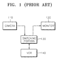
- a conventional time-lapse video recording system shown in FIG. 1 comprises a camera 110, a switching portion 130, a monitor 120, and a VCR 140.
- the switching portion 130 synchronizes each frame input from a plurality of external cameras 110 to be identical, and selectively outputs a video signal reproduced from the VCR 140 to the corresponding monitor 120. Also, the switching portion 130 adds a video-ID signal to a specific signal interval of a synchronous signal, and detects a video-ID signal previously inserted into a video signal reproduced from the VCR 140.
- the inserted video-ID signal includes various information, for example, a camera-ID, a frame-ID and time information among others.
- this time-lapse video recording reproducing system provides a switching portion 130 having insertion positions of a video-ID signal which are different from manufacturer to manufacturer. Therefore, in conventional time-lapse video recording reproducing systems, after investigating the switching portion 130 and ascertaining the corresponding insertion position, a video-ID signal is inserted into a specific signal interval which does not overlap the corresponding position. However, it is almost impossible to investigate every switching portion. Therefore, in the conventional time-lapse video recording reproducing system, if a switching portion of a specific manufacturing company is formed and used, incorrect operation can occur because of overlapping of insertion positions of a video-ID signal, and there is a problem in that compatibility between systems disappears.
- a method for processing a video-ID signal includes: detecting a starting position of a video-ID signal from an input video signal, compressing a video data started from the video-ID signal as a predetermined compression unit, and recording a starting position of the detected video-ID signal in a predetermined recording area; detecting the starting position of the video-ID signal recorded in the predetermined recording area, and decoding a video signal which inserts the video-ID signal to the starting position.
- an apparatus for recording a video signal includes: an ID position detecting means for detecting a starting position of a video-ID signal inserted into a predetermined interval of an input video signal; a video processing means for compressing a video data started from a starting position of the video-ID signal detected from the ID position detecting means as a predetermined compressing unit; a controlling means for recording the starting position of the video-ID signal detected from the ID position detecting means in a predetermined recording area of recording media.
- an apparatus for reproducing a video signal includes: an ID position detecting means for detecting a starting position of a video ID signal recorded in a predetermined recording area; a video processing means for decoding a video signal which inserts the video-ID signal to the starting position of the video-ID signal detected from the ID position detecting means.
- a frame is divided into an odd field (ODD) and an even field (EVEN) which are formed differently from an analog signal (ANALOG) and a digital signal (DIGITAL).
- ODD odd field
- EVEN even field
- ANALOG analog signal
- DIGITAL digital signal
- one NTCS type frame is formed of 525 horizontal synchronous signals.
- a video-ID hereinafter referred to as ID signal
- ID signal is different according to a switching portion, and has a different starting position at every maker.
- a starting position of an ID signal starts at 11H, 13H, 17H, and the ending position of an ID signal is not known.
- a sample level is a different according to luminance (Y) and color (Cb or Cr) signals.
- the ID signal is a low frequency signal existing only in the luminance (Y) signal and repeating High and Low. Therefore, the ID signal is detected with reference to the level of the luminance signal.
- FIG. 4 is a state transition diagram detecting the starting position of the ID signal according to the present invention.
- a detection starting signal if a detection starting signal is received, detection of the starting position of the ID signal begins.
- a luminance signal among input video signals is equal to or higher than a certain level, it is determined to be the start of an ID signal.
- the Find state compares the ID starting position of a next frame with that of a current frame (current).
- the Find state is transited to an Init state, and if the ID starting positions of two frames are the same, the Find state is transited to a Fixed state.
- the Fixed state detects the ID starting position of the third frame (third) and compares it with the ID starting position of the previous position (second).
- the Fixed state is transited to the Hold state, and if the ID starting positions are not the same, the Fixed state is transited to the Init state again, and the ID starting position is detected from the first frame.
- a Hold state stops a detecting process, and transmits an ID signal corresponding to the detected ID starting position, that is, an ID signal generated from the Fixed state, to a microcomputer.
- FIG. 5 is a flowchart illustrating the detection of the starting position of an ID signal according to the present invention.
- a starting position value of an ID signal transmitted to a microcomputer (ID_out), a pixel counter (cnt) for counting the number of continuous pixels including an ID data, and a frame counter (frame_cnt) for counting the number of frames are initialized (step 512).
- a standard of judgement of a level value of a luminance signal is determined as "180", and ID data is detected. Therefore, if the level value of a luminance signal (Y_dat) is "180", the pixel counter (cnt) increases by "1". The count is repeated until the number of pixels becomes "16" (steps 514, 516, 518, and 520).
- the standard of judgement of a level value of a luminance signal can be determined to be another value in addition to "180".
- a microcomputer compares the line value counted by a line counter (line cnt) with "17,” “13,” “11” corresponding to values of starting position lines (H) of an ID signal which is previously determined (step 522).
- the starting position line of an ID signal is determined by comparing the line value with the predetermined line value, the corresponding specific value (for example, "3,” “2,” “1") is stored in an ID memory (ID_temp) (steps 524, 526, 528, 530). For example, if the starting position line of an ID signal begins at "17”, "3" is stored in an ID memory (ID_temp).
- step 532 specific values stored in a previous ID memory (ID_temp) and a current ID memory (ID_temp) are compared (step 532).
- the frame counter (frame_cnt) increases by "1", and unless they are the same, the frame counter (frame_cnt) is determined to be "0", and initialized again (steps 534, and 536).
- a final ID memory (ID_temp) value is determined as the starting position value (ID_out) of an ID signal transmitted to a microcomputer (steps 538, 540).
- the number of frames detecting the starting position of an ID signal can be determined to be equal to or greater than 3.
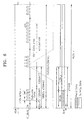
- FIG. 6 illustrates a track format recorded on recording media.
- effective compression data (including an ID signal) is recorded in a main data area, and the starting position information of an ID signal is recorded in a subcode data area.
- a video signal included in the main data area is divided into read data and dummy data.
- FIG. 7 is a block diagram showing an apparatus for processing a video-ID signal according to the present invention.
- the apparatus of FIG. 7 includes a switching portion 710, an ID detecting portion 720, a video signal processing portion 730, a channel processing portion 740, a record reproducing portion 750, and a microcomputer 760.
- the switching portion 710 After selecting a video signal input as field and/or frame unit, or selecting a video signal according to the order of the camera, the switching portion 710 inserts an ID signal to a video signal.
- the ID detecting portion 720 detects the starting position of an ID signal inserted into the switching portion 710, and applies the starting position of the detected ID signal to the microcomputer 760.
- the video signal processing portion 730 perceives the starting position of an ID signal detected from the ID detecting portion 720 as effective data, and performs compression.
- the channel processing portion 740 adds an error-correcting code to a video signal compressed from the video signal processing portion 730, and outputs the modulated video signal.
- the record reproducing portion 750 records a video signal modulated in the channel processing portion 740 in the form of a track in the recording media.
- the microcomputer 760 applies the starting signal for detecting an ID signal to an ID detecting portion 720, and receives the starting position of an ID signal from the ID detecting portion 720 and records it in the subcode data area through the record reproducing portion 750.
- the record reproducing portion 750 reproduces video data recorded in recording media, and the starting position of an ID signal recorded in the subcode data area to the microcomputer 760.
- the channel processing portion 740 performs channel decoding using an error-correcting code added to the video data.
- the microcomputer 760 receives the starting position of an ID signal from the record reproducing portion 750, and passes it to the ID detecting portion 720.
- the video processing portion 730 inserts an ID signal to a position of a video signal originally input with reference to the starting position of an ID signal detected from the ID detecting portion 720, and decodes the video signal.
- the ID detecting portion 720 receives the ID signal starting position from the microcomputer 760 and applies it to the video signal processing portion 730, and then, passes a video signal decoded from the video processing portion 730.
- the switching portion 710 displays a video signal passed from the ID detecting portion 720 on a monitor.
- FIG. 8 illustrates a video signal area input to the switching portion 710 of FIG. 7.
- an input video signal is formed of an effective data area (720 ⁇ 480) and an ID data area (720 ⁇ n).
- FIG. 9 illustrates a video signal area output to the switching portion 710 of FIG.7.
- an output video signal is indicated as the effective data area (720 ⁇ 480) including an ID data. Therefore, if both the ID data area and the effective data area are encoded together, an output video signal is formed of the same form of areas as the input video signal (FIG. 8).
- a video-ID signal is recorded in a time-lapse video recording reproducing system, and the video-ID signal is identified with a video signal to be compressed and restored, so that compatibility of switching portions of systems sold on the market can be maintained.
Landscapes
- Engineering & Computer Science (AREA)
- Multimedia (AREA)
- Signal Processing (AREA)
- Television Signal Processing For Recording (AREA)
- Signal Processing For Digital Recording And Reproducing (AREA)
- Closed-Circuit Television Systems (AREA)
Abstract
Description
Claims (9)
- A method for processing a video-ID signal in a recording and reproducing system, the method comprising the steps of:detecting a starting position of a video-ID signal from an input video signal, compressing a video signal started from the video-ID signal as a predetermined compression unit, and recording the starting position of the detected video-ID signal in a predetermined recording area;detecting the starting position of the video-ID signal recorded in the predetermined recording area, and decoding a video signal which inserts the video-ID signal into the starting position.
- The method of claim 1, wherein detecting the starting position of the video-ID signal comprises:determining an input video signal as the starting position of the video-ID signal if a luminance component among the input video signal is higher than a certain level;after detecting the starting position of the video signal determined in the above step in a present frame, comparing said starting position with the starting position of a video-ID signal of a next frame, and if the starting positions are the same, determining said starting position to be the starting position of a video-ID signal.
- The method of claim 2, wherein the step of detecting the starting position of the video-ID signal is performed repeatedly in at least one or more frames according to an external video signal.
- The method of claim 2, wherein the starting position of the video-ID signal exists in a synchronous line in which a predetermined number of luminance components higher than a certain level are continued.
- The method of claim 1, wherein the input video signal area is formed of an effective video data area and a separate video-ID signal area.
- The method of claim 1, wherein, in the reproduced video signal area, the video-ID signal area is included in the effective video data area.
- The method of claim 1, wherein the starting position of the video-ID signal is recorded in a subcode area of a digital track format.
- An apparatus for recording a video-ID signal in a recording and reproducing system, the apparatus comprising:ID position detecting means for detecting a starting position of a video-ID signal inserted into a predetermined interval of an input video data;video processing means for compressing a video data started from the starting position of the video-ID signal detected from the ID position detecting means as a predetermined compression unit;controlling means for recording the starting position of the video-ID signal detected from the ID position detecting means in a predetermined recording area of recording media.
- An apparatus for reproducing a video-ID signal in a recording and reproducing system, the apparatus comprising:ID position detecting means for detecting a starting position of a video-ID signal recorded in a predetermined recording area;video processing means for decoding a video signal which inserts the video-ID signal into the starting position of the video-ID signal detected from the ID position detecting means.
Applications Claiming Priority (2)
| Application Number | Priority Date | Filing Date | Title |
|---|---|---|---|
| KR2000038836 | 2000-07-07 | ||
| KR1020000038836A KR100677095B1 (en) | 2000-07-07 | 2000-07-07 | Image identification signal processing device and method |
Publications (3)
| Publication Number | Publication Date |
|---|---|
| EP1170947A2 true EP1170947A2 (en) | 2002-01-09 |
| EP1170947A3 EP1170947A3 (en) | 2004-11-24 |
| EP1170947B1 EP1170947B1 (en) | 2006-05-24 |
Family
ID=36580421
Family Applications (1)
| Application Number | Title | Priority Date | Filing Date |
|---|---|---|---|
| EP01103338A Expired - Lifetime EP1170947B1 (en) | 2000-07-07 | 2001-02-13 | Apparatus for processing video-ID signal and method thereof |
Country Status (6)
| Country | Link |
|---|---|
| US (1) | US7095950B2 (en) |
| EP (1) | EP1170947B1 (en) |
| JP (1) | JP3727245B2 (en) |
| KR (1) | KR100677095B1 (en) |
| CN (1) | CN1177473C (en) |
| DE (1) | DE60119838T2 (en) |
Family Cites Families (10)
| Publication number | Priority date | Publication date | Assignee | Title |
|---|---|---|---|---|
| US5303091A (en) * | 1988-11-10 | 1994-04-12 | Casio Computer Co., Ltd. | Digital audio tape recorder for recording character data with digital data |
| DE69027643T2 (en) * | 1989-10-04 | 1996-12-19 | Mitsubishi Electric Corp | Magnetic recording and playback device |
| JPH0547067A (en) * | 1991-08-19 | 1993-02-26 | Matsushita Electric Ind Co Ltd | Time lapse video tape recorder |
| JP2890924B2 (en) | 1991-09-24 | 1999-05-17 | 日本電気株式会社 | Surveillance video recording device |
| US5666238A (en) * | 1993-12-28 | 1997-09-09 | Kabushiki Kaisha Toshiba | Data sector control apparatus and method for disk storage system |
| MY114112A (en) * | 1994-12-22 | 2002-08-30 | Sony Corp | A recording medium having a first management area for managing a first attribute and a second management area for managing a second attribute of a program recorded in recoding area and a reproducing apparatus for reproducing the recoding medium |
| JP3640521B2 (en) | 1998-03-10 | 2005-04-20 | 松下電器産業株式会社 | Digital video recording / reproducing device |
| KR100296259B1 (en) | 1998-06-19 | 2001-10-26 | 구자홍 | Apparatus and method for adding / deleting image identification signal |
| JP2000013740A (en) | 1998-06-25 | 2000-01-14 | Victor Co Of Japan Ltd | Plural-video reproducing device and its identification signal processing method |
| JP2000134589A (en) | 1998-10-23 | 2000-05-12 | Matsushita Electric Ind Co Ltd | Television signal line search method and line search device |
-
2000
- 2000-07-07 KR KR1020000038836A patent/KR100677095B1/en not_active Expired - Fee Related
-
2001
- 2001-02-13 EP EP01103338A patent/EP1170947B1/en not_active Expired - Lifetime
- 2001-02-13 DE DE60119838T patent/DE60119838T2/en not_active Expired - Lifetime
- 2001-02-23 JP JP2001049247A patent/JP3727245B2/en not_active Expired - Fee Related
- 2001-02-26 CN CNB011049707A patent/CN1177473C/en not_active Expired - Fee Related
- 2001-03-15 US US09/808,033 patent/US7095950B2/en not_active Expired - Lifetime
Also Published As
| Publication number | Publication date |
|---|---|
| CN1332572A (en) | 2002-01-23 |
| EP1170947A3 (en) | 2004-11-24 |
| EP1170947B1 (en) | 2006-05-24 |
| DE60119838T2 (en) | 2006-10-19 |
| JP2002044603A (en) | 2002-02-08 |
| US7095950B2 (en) | 2006-08-22 |
| US20020018642A1 (en) | 2002-02-14 |
| JP3727245B2 (en) | 2005-12-14 |
| KR100677095B1 (en) | 2007-02-05 |
| CN1177473C (en) | 2004-11-24 |
| DE60119838D1 (en) | 2006-06-29 |
| KR20020004694A (en) | 2002-01-16 |
Similar Documents
| Publication | Publication Date | Title |
|---|---|---|
| USRE36338E (en) | Electronic still camera for recording and regenerating image data and sound data | |
| EP0639927B1 (en) | Digital video signal recording and reproducing apparatus | |
| US6192186B1 (en) | Method and apparatus for providing/reproducing MPEG data | |
| JP2000270347A (en) | Recording device and monitoring system using the recording device | |
| KR20000069436A (en) | Encoded video signal formatting | |
| EP1473935A1 (en) | Information processing apparatus and method | |
| US7095950B2 (en) | Apparatus and method for processing video-ID signal | |
| KR100200874B1 (en) | Selective recording device and method by motion detection | |
| EP0630155A2 (en) | Digital signal recording apparatus | |
| US20010005449A1 (en) | Multichannel image compression device and its method | |
| KR20020081342A (en) | Video recording/reproducing apparatus and video recording/reproducing method | |
| JP3197534B2 (en) | VCR with fast search | |
| JPH07231427A (en) | Compressed television signal processor | |
| US8340500B2 (en) | Video signal recording apparatus | |
| US5710857A (en) | Edit seaming in a video data recording/reproducing apparatus | |
| JP3258975B2 (en) | Error detection method of read data in video recording / reproducing apparatus | |
| JP3416560B2 (en) | Video recording apparatus, video reproducing apparatus, and video recording / reproducing apparatus | |
| KR100504363B1 (en) | Digital video recorder system and operating method thereof | |
| JPH08265751A (en) | Image regenerator based on MPEG system | |
| JP2003219362A (en) | Video recording / reproducing device, video recording / reproducing method, and monitoring system | |
| US6721116B1 (en) | Method for determining whether tape is recordable and apparatus therefor | |
| JP3026559B2 (en) | Apparatus and method for adding and deleting video identification signal | |
| JPH09102928A (en) | Device and method for recording and reproducing digital image data | |
| JP3568341B2 (en) | Video signal processing device | |
| JPH0965290A (en) | Image reproducing device |
Legal Events
| Date | Code | Title | Description |
|---|---|---|---|
| PUAI | Public reference made under article 153(3) epc to a published international application that has entered the european phase |
Free format text: ORIGINAL CODE: 0009012 |
|
| 17P | Request for examination filed |
Effective date: 20010213 |
|
| AK | Designated contracting states |
Kind code of ref document: A2 Designated state(s): AT BE CH CY DE DK ES FI FR GB GR IE IT LI LU MC NL PT SE TR |
|
| AX | Request for extension of the european patent |
Free format text: AL;LT;LV;MK;RO;SI |
|
| PUAL | Search report despatched |
Free format text: ORIGINAL CODE: 0009013 |
|
| AK | Designated contracting states |
Kind code of ref document: A3 Designated state(s): AT BE CH CY DE DK ES FI FR GB GR IE IT LI LU MC NL PT SE TR |
|
| AX | Request for extension of the european patent |
Extension state: AL LT LV MK RO SI |
|
| 17Q | First examination report despatched |
Effective date: 20050119 |
|
| AKX | Designation fees paid |
Designated state(s): DE FR GB |
|
| GRAP | Despatch of communication of intention to grant a patent |
Free format text: ORIGINAL CODE: EPIDOSNIGR1 |
|
| GRAS | Grant fee paid |
Free format text: ORIGINAL CODE: EPIDOSNIGR3 |
|
| GRAA | (expected) grant |
Free format text: ORIGINAL CODE: 0009210 |
|
| AK | Designated contracting states |
Kind code of ref document: B1 Designated state(s): DE FR GB |
|
| REG | Reference to a national code |
Ref country code: GB Ref legal event code: FG4D |
|
| REF | Corresponds to: |
Ref document number: 60119838 Country of ref document: DE Date of ref document: 20060629 Kind code of ref document: P |
|
| ET | Fr: translation filed | ||
| PLBE | No opposition filed within time limit |
Free format text: ORIGINAL CODE: 0009261 |
|
| STAA | Information on the status of an ep patent application or granted ep patent |
Free format text: STATUS: NO OPPOSITION FILED WITHIN TIME LIMIT |
|
| 26N | No opposition filed |
Effective date: 20070227 |
|
| REG | Reference to a national code |
Ref country code: FR Ref legal event code: PLFP Year of fee payment: 16 |
|
| PGFP | Annual fee paid to national office [announced via postgrant information from national office to epo] |
Ref country code: DE Payment date: 20160120 Year of fee payment: 16 |
|
| PGFP | Annual fee paid to national office [announced via postgrant information from national office to epo] |
Ref country code: GB Payment date: 20160121 Year of fee payment: 16 Ref country code: FR Payment date: 20160126 Year of fee payment: 16 |
|
| REG | Reference to a national code |
Ref country code: DE Ref legal event code: R119 Ref document number: 60119838 Country of ref document: DE |
|
| GBPC | Gb: european patent ceased through non-payment of renewal fee |
Effective date: 20170213 |
|
| REG | Reference to a national code |
Ref country code: FR Ref legal event code: ST Effective date: 20171031 |
|
| PG25 | Lapsed in a contracting state [announced via postgrant information from national office to epo] |
Ref country code: DE Free format text: LAPSE BECAUSE OF NON-PAYMENT OF DUE FEES Effective date: 20170901 Ref country code: FR Free format text: LAPSE BECAUSE OF NON-PAYMENT OF DUE FEES Effective date: 20170228 |
|
| PG25 | Lapsed in a contracting state [announced via postgrant information from national office to epo] |
Ref country code: GB Free format text: LAPSE BECAUSE OF NON-PAYMENT OF DUE FEES Effective date: 20170213 |