EP1170827A2 - Electric connector - Google Patents
Electric connector Download PDFInfo
- Publication number
- EP1170827A2 EP1170827A2 EP01116072A EP01116072A EP1170827A2 EP 1170827 A2 EP1170827 A2 EP 1170827A2 EP 01116072 A EP01116072 A EP 01116072A EP 01116072 A EP01116072 A EP 01116072A EP 1170827 A2 EP1170827 A2 EP 1170827A2
- Authority
- EP
- European Patent Office
- Prior art keywords
- contact
- opposing side
- bridge
- tab
- side walls
- Prior art date
- Legal status (The legal status is an assumption and is not a legal conclusion. Google has not performed a legal analysis and makes no representation as to the accuracy of the status listed.)
- Granted
Links
- 230000013011 mating Effects 0.000 claims abstract description 30
- 238000003780 insertion Methods 0.000 claims abstract description 17
- 230000037431 insertion Effects 0.000 claims abstract description 17
- 230000007704 transition Effects 0.000 claims description 7
- 230000014759 maintenance of location Effects 0.000 claims description 3
- 230000000063 preceeding effect Effects 0.000 claims 6
- 230000000295 complement effect Effects 0.000 description 3
- 238000010276 construction Methods 0.000 description 1
- 238000002788 crimping Methods 0.000 description 1
- 230000000994 depressogenic effect Effects 0.000 description 1
- 238000010348 incorporation Methods 0.000 description 1
- 238000004519 manufacturing process Methods 0.000 description 1
- 239000000463 material Substances 0.000 description 1
- 239000002184 metal Substances 0.000 description 1
- 238000000034 method Methods 0.000 description 1
- 238000009751 slip forming Methods 0.000 description 1
- 238000005728 strengthening Methods 0.000 description 1
Images


Classifications
-
- H—ELECTRICITY
- H01—ELECTRIC ELEMENTS
- H01R—ELECTRICALLY-CONDUCTIVE CONNECTIONS; STRUCTURAL ASSOCIATIONS OF A PLURALITY OF MUTUALLY-INSULATED ELECTRICAL CONNECTING ELEMENTS; COUPLING DEVICES; CURRENT COLLECTORS
- H01R13/00—Details of coupling devices of the kinds covered by groups H01R12/70 or H01R24/00 - H01R33/00
- H01R13/02—Contact members
- H01R13/10—Sockets for co-operation with pins or blades
- H01R13/11—Resilient sockets
- H01R13/113—Resilient sockets co-operating with pins or blades having a rectangular transverse section
-
- H—ELECTRICITY
- H01—ELECTRIC ELEMENTS
- H01R—ELECTRICALLY-CONDUCTIVE CONNECTIONS; STRUCTURAL ASSOCIATIONS OF A PLURALITY OF MUTUALLY-INSULATED ELECTRICAL CONNECTING ELEMENTS; COUPLING DEVICES; CURRENT COLLECTORS
- H01R13/00—Details of coupling devices of the kinds covered by groups H01R12/70 or H01R24/00 - H01R33/00
- H01R13/02—Contact members
- H01R13/193—Means for increasing contact pressure at the end of engagement of coupling part, e.g. zero insertion force or no friction
Definitions
- the present invention relates to an electrical contact and in particular to an electrical contact for receiving a complementary tab terminal.
- an electrical connection between a tab terminal and a complementary electrical contact.
- One particular style of an electrical contact includes a base that has a bottom surface with two upstanding and opposing side walls from which contact arms are rolled over to form longitudinally extending contact surfaces above the bottom. When the tab is inserted into this type of electrical contact, it is positioned between the bottom and the contact surfaces.
- An example of a contact of this type is presented in EP 0 043 655. While it is advantageous that a contact of this type can be produced from a single piece of metal, the related contact forces during mating are occasionally undesirably high.
- a contact having a pivoting contact spring mounted over a base with a bottom surface and two opposing side walls.
- the pivoting contact spring is typically a separate piece and coupled to the side walls such that a tab-receiving space is formed under the pivoting contact.
- An example of this type of contact is disclosed in GB 2 315 929. While a contact of this type has reduced insertion forces, manufacturing expenses are high due to the two-part construction.
- the electrical contact could be adapted to prevent damage to or overstressing of the contact spring during insertion of the mating tab terminal. It would additionally be advantageous if the contact could be adapted with a locking member such that withdraw forces of the tab terminal are substantially larger than insertion forces. Finally, it would be advantageous if the electrical contact could be manufactured from a single piece of material.
- An improved electrical contact has a U-shaped base having a bottom and two opposing side walls that define a tab-receiving channel.
- the base has an open forward end for receiving a mating tab terminal and a rearward end with a middle region therebetween.
- a contact spring is disposed over the bottom and has a bridge which spans the bottom between the opposing side walls in the middle region of the base.
- a first contact arm extends from the bridge towards the forward end and converges towards the bottom to a first contact point and then diverges to a free end thereby defining a mating tab insertion mouth.
- a second contact arm extends from the bridge towards the rearward end and converges towards the base to a second contact point that is disposed closer to the base than the first contact point.
- the bridge is continuous with one of the opposing side walls and includes a free end that is attached to the other opposing side wall.
- tabs located along the side walls toward the forward end can extend out over the bottom such that the mating tab terminal is properly received so as to not damage the contact spring.
- a further tab may be provided that overlies the contact spring and prevents overstressing of the spring. This tab may also advantageously be used to locate the electrical contact within the housing.
- the second contact arm may include a tab terminal locating portion beyond the second contact point to prevent overinsertion of the mating tab terminal.
- a locking protrusion may be provided on a spring arm within the bottom of the base, where the locking protrusion extends above the bottom for engaging a complementary feature in the mating tab terminal.
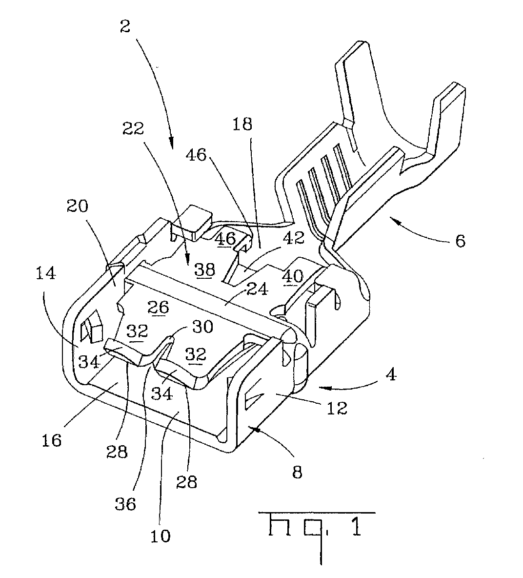
- an electrical contact 2 for receiving a mating tab terminal 3 ( Figure 3) includes a receptacle end 4 and a termination end 6.
- the termination end 6 is configured for crimping to an insulated conductive wire, as is well known.
- the receptacle end 4 includes a U-shaped base 8 having a bottom 10 and opposing side walls 12,14.
- the U-shaped base 8 has an open forward end 16, a rearward end 18 and a middle region 20 therebetween.
- a contact spring 22 is disposed over the bottom 10.
- the contact spring 22 includes a bridge 24 that spans the bottom 10 and is coupled to the opposing side walls 12,14.
- a first contact arm 26 extends towards the forward end 16 and converges towards the bottom 10 to a first contact point 28.
- the first contact arm 26 is bifurcated by slot 30 into two contact arms 32. It is also possible to construct the first contact arm 26 without the slot 30 or with more than one slot 30. The first contact arm 26 then diverges outward to free end 34 defining a mating tab receiving mouth 36.
- a second contact arm 38 extends from the bridge 24 towards the rearward end 18 of the base 8.
- the second contact arm 38 is also bifurcated into two sub-contact arms 40 by a slot 42.
- the second contact arm 38 also converges towards the bottom 10 to a second contact point 44 as best shown in Figure 3.
- the second contact arm 38 further includes a downwardly folded stop tab 46 that further extends towards the bottom 10 such that the mating tab 3 can not be overinserted as best seen in Figure 5.
- the bridge 24 is continuously formed with one of the side walls 12 through a transition section 48.
- the transition section 48 may be defined by cutouts 50 on either side thereof that extend into the side wall 12. These cut outs 50 may extend to the bottom 10 or it is also possible to have the transition 48 formed along the top edge 52 of side wall 12 without these cut outs 50 when the side wall 12 is properly configured.
- the bridge 24 further includes a tab 54 located opposite to the transition section 48 that extends through an aperture 56 in the opposing side wall 14. The clearance between the tab 54 and the aperture 56 is preferably minimised to prevent undue flexing of the contact spring 22.
- the contact spring 22 may be strengthened by incorporating protuberances 58 in the bridge 24 and/or side wall 12. Further, an additional protuberance 60 may be disposed above the aperture 56 to strengthen that region. The protuberances 58, by strengthening the contact spring 22 in the bridge region 24, may be used to enhance the contact forces exerted by the contact spring 22.
- a pair of anti-twist tabs 62 Located toward the forward end 16 of the base 8 are a pair of anti-twist tabs 62, these anti-twist tabs 62 are configured so as not to interfere with the contact spring 22 but to extend over the bottom 10 at a height(D) generally corresponding to slightly more than the thickness of the mating tab terminal 3 so that the mating tab terminal 3 is prevented from being inserted into the electrical contact 2 in a twisted orientation that may cause damage to the contact spring 22.
- an anti-overstress tab 64 is disposed toward the rearward end 18 of the base 8. This anti-overstress tab 64 overlies a protrusion 66 of the contact spring 22. The anti-overstress tab 64 prevents the contact spring 22 from being over-pivoted and potentially reducing its resiliency.
- An additional tab 68 that is similarly configured to the anti-overstress tab 64 but does not overlie the contact spring 22 is provided in the opposite wall 12 thereof. Both the anti-overstress tab 64 and the additional tab 68 include a corresponding rear edge 70 for retaining the electrical contact 2 within a housing in a conventional manner.
- a locking element 72 is formed in the bottom 10 and extends toward contact arm 26.
- the Locking element 72 has a retention edge 74 at a free end.
- the mating tab 3 With reference now to Figures 3-5, insertion of the mating tab 3 will be described. With reference first to Figure 3, the mating tab 3 is inserted into the contact mouth 36 such that the tab first becomes engaged with the first contact point 28 along the first contact arm 26. As the first contact arm 26 is relatively long as measured between the first contact point 28 and the bridge 24 and the normal rest spacing between the bottom 10 and the first contact point 28 is only slightly less than the thickness of the mating tab 3, the mating tab 3 encounters only minimal insertion force resistance. This insertion force is shown generally in region A of Figure 6. Upon further insertion of the mating tab 3, the mating tab 3 comes into contact with the locking element 72 and the retention edge 74 engages an opening 76 in the mating tab 3.
- the locking element 72 is deflected out of the way and resiles into the opening 76 as the mating tab 3 is inserted through the second contact point 44.
- the insertion force rises as shown in region B of Figure 6.
- the relatively short nature of the contact arm 38 between the bridge 24 and the contact point 44 provides for a stiff and maintainable contact force upon the mating tab 3 that is maintained as a result of the transition section 48 and the interengagement of the tab 54 in the aperture 56.
- the mating tab 3 can be further inserted but not over-inserted because it abuts the stop tab 46.
Landscapes
- Coupling Device And Connection With Printed Circuit (AREA)
- Details Of Connecting Devices For Male And Female Coupling (AREA)
Abstract
Description
Claims (10)
- An electrical contact (2) comprises a U-shaped base (8) having a bottom (10) and two opposing side walls (12,14) therealong that define a tab-receiving channel, the base (8) has an open forward end (16) for receiving a mating tab terminal (3) and a rearward end (18) with a middle region (20) therebetween, and a contact spring (22) disposed over the bottom (10) that has a bridge (24) spanning the bottom (10) and coupled to the opposing side walls (12,14) in the middle region (20) of the base (10) where a first contact arm (26) extends from the bridge (24) towards the forward end (16) and converges towards the bottom (10) to a first contact point (28) and then diverges to a free end (34) thereby defining a mating tab insertion mouth (36) and a second contact arm (40) extending from the bridge (24) towards the rearward end (18) and converging towards the base (10) to a second contact point (44) that is disposed closer to the base (10) than the first contact point (28) wherein the improvement comprises the bridge (24) being continuous with one of the opposing side walls (12) and the bridge (24) includes a free end opposite thereto that is attached to the other opposing side wall (14).
- The electrical contact (2) of claim 1, wherein the bridge (24) includes a tab (54) at the free end that extends into an aperture (56) in the other opposing side wall (14).
- The electrical contact (2) of claim 1 or 2, wherein the bridge (24) is continuous with the one of the opposing side walls (12) through a transition (48).
- The electrical contact (2) of claim 3, wherein the transition (48) is defined by a pair of slots (50) on either side thereof that extend into the one of the opposing side walls.
- The electrical contact (2) of anyone of the preceeding claims, wherein the bridge (24) includes a protuberance (58) to enhance the strength thereof.
- The electrical contact (2) of any one of the preceeding claims wherein at least one of the opposing side walls (12,14) includes a protuberance (58,60) to enhance the strength thereof.
- The electrical contact (2) of any one of the preceeding claims wherein the sidewalls (12,14) include locating tabs (62) extending over the bottom (10) at the forward end (16) to assure proper orientation of the mating tab (3).
- The electrical contact (2) of any one of the preceeding claims wherein one of the opposing side walls (12,14) includes an overstress tab (64,68) extending therefrom and over the contact spring (22).
- The electrical contact (2) of any one of the preceeding claims wherein one of the opposing side walls includes a tab (64,68) having a retention edge (70) for retaining the contact (2) in a housing.
- The electrical contact (2) of any one of the preceeding claims wherein a locking arm (72) is formed in the bottom.
Applications Claiming Priority (2)
| Application Number | Priority Date | Filing Date | Title |
|---|---|---|---|
| GB0016790 | 2000-07-07 | ||
| GBGB0016790.8A GB0016790D0 (en) | 2000-07-07 | 2000-07-07 | Electrical connector |
Publications (3)
| Publication Number | Publication Date |
|---|---|
| EP1170827A2 true EP1170827A2 (en) | 2002-01-09 |
| EP1170827A3 EP1170827A3 (en) | 2002-09-18 |
| EP1170827B1 EP1170827B1 (en) | 2009-10-21 |
Family
ID=9895276
Family Applications (1)
| Application Number | Title | Priority Date | Filing Date |
|---|---|---|---|
| EP01116072A Expired - Lifetime EP1170827B1 (en) | 2000-07-07 | 2001-07-03 | Electric connector |
Country Status (7)
| Country | Link |
|---|---|
| US (1) | US6527600B2 (en) |
| EP (1) | EP1170827B1 (en) |
| AT (1) | ATE446598T1 (en) |
| BR (1) | BRPI0102765B1 (en) |
| DE (1) | DE60140237D1 (en) |
| ES (1) | ES2333095T3 (en) |
| GB (1) | GB0016790D0 (en) |
Cited By (2)
| Publication number | Priority date | Publication date | Assignee | Title |
|---|---|---|---|---|
| EP1786065A1 (en) * | 2005-11-15 | 2007-05-16 | Sumitomo Wiring Systems, Ltd. | A terminal fitting and a connector provided therewith |
| WO2011143807A1 (en) | 2010-05-18 | 2011-11-24 | Harting Electronics Gmbh & Co. Kg | Contact spring for plug connector socket |
Families Citing this family (17)
| Publication number | Priority date | Publication date | Assignee | Title |
|---|---|---|---|---|
| JP2004152594A (en) * | 2002-10-30 | 2004-05-27 | Molex Inc | Electric terminal |
| US6683789B1 (en) | 2003-04-28 | 2004-01-27 | Motorola, Inc. | Electronic control module for a removable connector and methods of assembling same |
| SG149733A1 (en) * | 2007-07-31 | 2009-02-27 | J S T U K Ltd | Receptacle terminal |
| DE102008032837A1 (en) * | 2008-07-14 | 2010-01-21 | Phoenix Contact Gmbh & Co. Kg | Electrical connection device |
| WO2010134572A1 (en) * | 2009-05-20 | 2010-11-25 | 行田電線株式会社 | Connecting terminal, terminal connecting structure and terminal box |
| WO2013108874A1 (en) * | 2012-01-20 | 2013-07-25 | 矢崎総業株式会社 | Electrical connector and method for producing same |
| ES2418779B1 (en) * | 2012-02-09 | 2014-09-15 | Orkli, S.Coop. | Thermocouple connector adapted to a gas and thermocouple solenoid valve comprising the connector |
| CN104577376A (en) * | 2014-12-29 | 2015-04-29 | 温州市珠城电气有限公司 | Straight duckbilled terminal |
| CN104577361A (en) * | 2014-12-29 | 2015-04-29 | 温州市珠城电气有限公司 | Flag-shaped duckbilled terminal |
| US10027037B2 (en) * | 2016-07-06 | 2018-07-17 | Te Connectivity Corporation | Terminal with reduced normal force |
| DE102016221351A1 (en) * | 2016-10-28 | 2018-05-03 | Te Connectivity Germany Gmbh | Flat contact socket with extension arm |
| JP6576979B2 (en) * | 2017-07-20 | 2019-09-18 | 矢崎総業株式会社 | Terminal connection structure |
| CN208111733U (en) * | 2018-03-13 | 2018-11-16 | 泰科电子(上海)有限公司 | Connection terminal |
| CN211789804U (en) * | 2020-02-19 | 2020-10-27 | 泰科电子(上海)有限公司 | electrical connector |
| JP7396188B2 (en) * | 2020-04-30 | 2023-12-12 | 住友電装株式会社 | Female terminal fitting |
| US11264735B1 (en) * | 2020-08-28 | 2022-03-01 | TE Connectivity Services Gmbh | Electrical terminal for terminating a wide size range of magnet wires |
| DE102021108272A1 (en) * | 2021-03-31 | 2022-10-06 | Te Connectivity Germany Gmbh | Contact element for an electrical plug |
Family Cites Families (10)
| Publication number | Priority date | Publication date | Assignee | Title |
|---|---|---|---|---|
| EP0043655B1 (en) | 1980-06-27 | 1983-11-02 | AMP INCORPORATED (a New Jersey corporation) | Electrical terminal with a release member |
| FR2514573A1 (en) * | 1981-10-12 | 1983-04-15 | Labinal | Female electrical contact for flat pin male connectors - is formed from single metal sheet made into two blades to provide electrical contact of large surface area |
| US4679887A (en) * | 1982-03-24 | 1987-07-14 | Amp Incorporated | Electrical terminal |
| US4487471A (en) | 1983-01-06 | 1984-12-11 | Minnesota Mining And Manufacturing Company | Socket connector |
| US4552425A (en) * | 1983-07-27 | 1985-11-12 | Amp Incorporated | High current connector |
| US4713026A (en) * | 1986-10-08 | 1987-12-15 | Interlock Corporation | Tab receptacle terminal having improved electrical and mechanical features |
| JP3285101B2 (en) * | 1993-01-21 | 2002-05-27 | 矢崎総業株式会社 | Female terminal |
| IT1261615B (en) * | 1993-10-18 | 1996-05-23 | Framatome Connectors Italia | ELECTRIC TERMINAL FEMALE |
| GB9616054D0 (en) | 1996-07-31 | 1996-09-11 | Amp Espa Ola S A | Low insertion force receptacle contact |
| DE10014116A1 (en) * | 2000-03-22 | 2001-09-27 | Delphi Tech Inc | Connection element for electrical pluggable element, especially flat plug, uses two-arm-type contact rocker arranged in housing about vertical axis |
-
2000
- 2000-07-07 GB GBGB0016790.8A patent/GB0016790D0/en not_active Ceased
-
2001
- 2001-06-26 US US09/891,437 patent/US6527600B2/en not_active Expired - Lifetime
- 2001-07-03 EP EP01116072A patent/EP1170827B1/en not_active Expired - Lifetime
- 2001-07-03 DE DE60140237T patent/DE60140237D1/en not_active Expired - Lifetime
- 2001-07-03 ES ES01116072T patent/ES2333095T3/en not_active Expired - Lifetime
- 2001-07-03 AT AT01116072T patent/ATE446598T1/en not_active IP Right Cessation
- 2001-07-06 BR BRPI0102765A patent/BRPI0102765B1/en not_active IP Right Cessation
Cited By (4)
| Publication number | Priority date | Publication date | Assignee | Title |
|---|---|---|---|---|
| EP1786065A1 (en) * | 2005-11-15 | 2007-05-16 | Sumitomo Wiring Systems, Ltd. | A terminal fitting and a connector provided therewith |
| WO2011143807A1 (en) | 2010-05-18 | 2011-11-24 | Harting Electronics Gmbh & Co. Kg | Contact spring for plug connector socket |
| JP2013529362A (en) * | 2010-05-18 | 2013-07-18 | ハルティング エレクトロニクス ゲゼルシャフト ミット ベシュレンクテル ハフツング ウント コンパニー コマンディートゲゼルシャフト | Contact spring for plug connector socket |
| US8758068B2 (en) | 2010-05-18 | 2014-06-24 | HARTING Electronics GmbH | Contact spring for plug connector socket |
Also Published As
| Publication number | Publication date |
|---|---|
| GB0016790D0 (en) | 2000-08-30 |
| BR0102765A (en) | 2002-02-26 |
| DE60140237D1 (en) | 2009-12-03 |
| ES2333095T3 (en) | 2010-02-17 |
| EP1170827A3 (en) | 2002-09-18 |
| US20020022412A1 (en) | 2002-02-21 |
| US6527600B2 (en) | 2003-03-04 |
| EP1170827B1 (en) | 2009-10-21 |
| BRPI0102765B1 (en) | 2016-07-05 |
| ATE446598T1 (en) | 2009-11-15 |
Similar Documents
| Publication | Publication Date | Title |
|---|---|---|
| EP1170827B1 (en) | Electric connector | |
| EP0618644B1 (en) | Electrical terminal | |
| US6152788A (en) | Female terminal | |
| EP0147076B1 (en) | Electrical terminal having a receptacle contact section of low insertion force and terminating section therefor | |
| EP0517077B1 (en) | Electrical contact | |
| US4699444A (en) | Electrical receptacle which assures positive connection | |
| EP0830712B1 (en) | Electrical terminal | |
| EP1890363B1 (en) | A female terminal fitting | |
| EP1107376A2 (en) | Female connection terminal | |
| EP0700124A2 (en) | Electrical contact having improved locking lances | |
| EP0389955A2 (en) | A double locking connector for an electrical terminal | |
| EP0678936A1 (en) | Miniature anti-fretting receptacle terminal | |
| US5681190A (en) | Torsional blade receptacle | |
| EP1617521A1 (en) | A Receptacle Terminal | |
| US5775932A (en) | Electrical connector | |
| US20010049237A1 (en) | Female terminal fitting | |
| EP0656673A2 (en) | Low insertion force receptacle terminal | |
| JPH0831490A (en) | Female terminal fitting | |
| EP0685907A2 (en) | Contact and connector | |
| JPH08321343A (en) | Female terminal fitting | |
| US6325679B2 (en) | Receptacle terminal and forming method of the same | |
| US6997761B2 (en) | Electrical contact element | |
| JPH0927368A (en) | Female terminal | |
| US6551151B2 (en) | Male terminal with curved interconnecting portion | |
| WO1997004502A1 (en) | Electrical receptacle terminal |
Legal Events
| Date | Code | Title | Description |
|---|---|---|---|
| PUAI | Public reference made under article 153(3) epc to a published international application that has entered the european phase |
Free format text: ORIGINAL CODE: 0009012 |
|
| AK | Designated contracting states |
Kind code of ref document: A2 Designated state(s): AT BE CH CY DE DK ES FI FR GB GR IE IT LI LU MC NL PT SE TR |
|
| AX | Request for extension of the european patent |
Free format text: AL;LT;LV;MK;RO;SI |
|
| PUAL | Search report despatched |
Free format text: ORIGINAL CODE: 0009013 |
|
| AK | Designated contracting states |
Kind code of ref document: A3 Designated state(s): AT BE CH CY DE DK ES FI FR GB GR IE IT LI LU MC NL PT SE TR |
|
| AX | Request for extension of the european patent |
Free format text: AL;LT;LV;MK;RO;SI |
|
| 17P | Request for examination filed |
Effective date: 20020910 |
|
| AKX | Designation fees paid |
Designated state(s): AT BE CH CY DE DK ES FI FR GB GR IE IT LI LU MC NL PT SE TR |
|
| GRAP | Despatch of communication of intention to grant a patent |
Free format text: ORIGINAL CODE: EPIDOSNIGR1 |
|
| RAP1 | Party data changed (applicant data changed or rights of an application transferred) |
Owner name: TYCO ELECTRONICS AMP ESPANA S.A. |
|
| GRAS | Grant fee paid |
Free format text: ORIGINAL CODE: EPIDOSNIGR3 |
|
| GRAA | (expected) grant |
Free format text: ORIGINAL CODE: 0009210 |
|
| AK | Designated contracting states |
Kind code of ref document: B1 Designated state(s): AT BE CH CY DE DK ES FI FR GB GR IE IT LI LU MC NL PT SE TR |
|
| REG | Reference to a national code |
Ref country code: GB Ref legal event code: FG4D |
|
| REG | Reference to a national code |
Ref country code: CH Ref legal event code: EP |
|
| REG | Reference to a national code |
Ref country code: IE Ref legal event code: FG4D |
|
| REF | Corresponds to: |
Ref document number: 60140237 Country of ref document: DE Date of ref document: 20091203 Kind code of ref document: P |
|
| REG | Reference to a national code |
Ref country code: ES Ref legal event code: FG2A Ref document number: 2333095 Country of ref document: ES Kind code of ref document: T3 |
|
| NLV1 | Nl: lapsed or annulled due to failure to fulfill the requirements of art. 29p and 29m of the patents act | ||
| PG25 | Lapsed in a contracting state [announced via postgrant information from national office to epo] |
Ref country code: SE Free format text: LAPSE BECAUSE OF FAILURE TO SUBMIT A TRANSLATION OF THE DESCRIPTION OR TO PAY THE FEE WITHIN THE PRESCRIBED TIME-LIMIT Effective date: 20091021 Ref country code: FI Free format text: LAPSE BECAUSE OF FAILURE TO SUBMIT A TRANSLATION OF THE DESCRIPTION OR TO PAY THE FEE WITHIN THE PRESCRIBED TIME-LIMIT Effective date: 20091021 Ref country code: PT Free format text: LAPSE BECAUSE OF FAILURE TO SUBMIT A TRANSLATION OF THE DESCRIPTION OR TO PAY THE FEE WITHIN THE PRESCRIBED TIME-LIMIT Effective date: 20100222 |
|
| PG25 | Lapsed in a contracting state [announced via postgrant information from national office to epo] |
Ref country code: BE Free format text: LAPSE BECAUSE OF FAILURE TO SUBMIT A TRANSLATION OF THE DESCRIPTION OR TO PAY THE FEE WITHIN THE PRESCRIBED TIME-LIMIT Effective date: 20091021 Ref country code: AT Free format text: LAPSE BECAUSE OF FAILURE TO SUBMIT A TRANSLATION OF THE DESCRIPTION OR TO PAY THE FEE WITHIN THE PRESCRIBED TIME-LIMIT Effective date: 20091021 |
|
| PG25 | Lapsed in a contracting state [announced via postgrant information from national office to epo] |
Ref country code: DK Free format text: LAPSE BECAUSE OF FAILURE TO SUBMIT A TRANSLATION OF THE DESCRIPTION OR TO PAY THE FEE WITHIN THE PRESCRIBED TIME-LIMIT Effective date: 20091021 |
|
| PLBE | No opposition filed within time limit |
Free format text: ORIGINAL CODE: 0009261 |
|
| STAA | Information on the status of an ep patent application or granted ep patent |
Free format text: STATUS: NO OPPOSITION FILED WITHIN TIME LIMIT |
|
| 26N | No opposition filed |
Effective date: 20100722 |
|
| PG25 | Lapsed in a contracting state [announced via postgrant information from national office to epo] |
Ref country code: GR Free format text: LAPSE BECAUSE OF FAILURE TO SUBMIT A TRANSLATION OF THE DESCRIPTION OR TO PAY THE FEE WITHIN THE PRESCRIBED TIME-LIMIT Effective date: 20100122 |
|
| PG25 | Lapsed in a contracting state [announced via postgrant information from national office to epo] |
Ref country code: MC Free format text: LAPSE BECAUSE OF NON-PAYMENT OF DUE FEES Effective date: 20100731 |
|
| REG | Reference to a national code |
Ref country code: CH Ref legal event code: PL |
|
| GBPC | Gb: european patent ceased through non-payment of renewal fee |
Effective date: 20100703 |
|
| PG25 | Lapsed in a contracting state [announced via postgrant information from national office to epo] |
Ref country code: LI Free format text: LAPSE BECAUSE OF NON-PAYMENT OF DUE FEES Effective date: 20100731 Ref country code: CH Free format text: LAPSE BECAUSE OF NON-PAYMENT OF DUE FEES Effective date: 20100731 |
|
| PG25 | Lapsed in a contracting state [announced via postgrant information from national office to epo] |
Ref country code: IE Free format text: LAPSE BECAUSE OF NON-PAYMENT OF DUE FEES Effective date: 20100703 Ref country code: GB Free format text: LAPSE BECAUSE OF NON-PAYMENT OF DUE FEES Effective date: 20100703 |
|
| PG25 | Lapsed in a contracting state [announced via postgrant information from national office to epo] |
Ref country code: CY Free format text: LAPSE BECAUSE OF FAILURE TO SUBMIT A TRANSLATION OF THE DESCRIPTION OR TO PAY THE FEE WITHIN THE PRESCRIBED TIME-LIMIT Effective date: 20091021 |
|
| PG25 | Lapsed in a contracting state [announced via postgrant information from national office to epo] |
Ref country code: LU Free format text: LAPSE BECAUSE OF NON-PAYMENT OF DUE FEES Effective date: 20100703 Ref country code: NL Free format text: LAPSE BECAUSE OF FAILURE TO SUBMIT A TRANSLATION OF THE DESCRIPTION OR TO PAY THE FEE WITHIN THE PRESCRIBED TIME-LIMIT Effective date: 20091021 |
|
| PG25 | Lapsed in a contracting state [announced via postgrant information from national office to epo] |
Ref country code: TR Free format text: LAPSE BECAUSE OF FAILURE TO SUBMIT A TRANSLATION OF THE DESCRIPTION OR TO PAY THE FEE WITHIN THE PRESCRIBED TIME-LIMIT Effective date: 20091021 |
|
| PGFP | Annual fee paid to national office [announced via postgrant information from national office to epo] |
Ref country code: FR Payment date: 20130717 Year of fee payment: 13 |
|
| REG | Reference to a national code |
Ref country code: FR Ref legal event code: ST Effective date: 20150331 |
|
| PG25 | Lapsed in a contracting state [announced via postgrant information from national office to epo] |
Ref country code: FR Free format text: LAPSE BECAUSE OF NON-PAYMENT OF DUE FEES Effective date: 20140731 |
|
| REG | Reference to a national code |
Ref country code: DE Ref legal event code: R082 Ref document number: 60140237 Country of ref document: DE Representative=s name: SCHMITT-NILSON SCHRAUD WAIBEL WOHLFROM PATENTA, DE |
|
| PGFP | Annual fee paid to national office [announced via postgrant information from national office to epo] |
Ref country code: DE Payment date: 20200624 Year of fee payment: 20 Ref country code: ES Payment date: 20200803 Year of fee payment: 20 |
|
| PGFP | Annual fee paid to national office [announced via postgrant information from national office to epo] |
Ref country code: IT Payment date: 20200610 Year of fee payment: 20 |
|
| REG | Reference to a national code |
Ref country code: DE Ref legal event code: R071 Ref document number: 60140237 Country of ref document: DE |
|
| REG | Reference to a national code |
Ref country code: ES Ref legal event code: FD2A Effective date: 20220127 |
|
| PG25 | Lapsed in a contracting state [announced via postgrant information from national office to epo] |
Ref country code: ES Free format text: LAPSE BECAUSE OF EXPIRATION OF PROTECTION Effective date: 20210704 |