EP1170762A2 - Arrangement having a contact element which can be brought into contact with another contact element - Google Patents
Arrangement having a contact element which can be brought into contact with another contact element Download PDFInfo
- Publication number
- EP1170762A2 EP1170762A2 EP01116018A EP01116018A EP1170762A2 EP 1170762 A2 EP1170762 A2 EP 1170762A2 EP 01116018 A EP01116018 A EP 01116018A EP 01116018 A EP01116018 A EP 01116018A EP 1170762 A2 EP1170762 A2 EP 1170762A2
- Authority
- EP
- European Patent Office
- Prior art keywords
- contact elements
- contact
- arrangement according
- arc
- voltage
- Prior art date
- Legal status (The legal status is an assumption and is not a legal conclusion. Google has not performed a legal analysis and makes no representation as to the accuracy of the status listed.)
- Withdrawn
Links
Images
Classifications
-
- H—ELECTRICITY
- H01—ELECTRIC ELEMENTS
- H01H—ELECTRIC SWITCHES; RELAYS; SELECTORS; EMERGENCY PROTECTIVE DEVICES
- H01H9/00—Details of switching devices, not covered by groups H01H1/00 - H01H7/00
- H01H9/54—Circuit arrangements not adapted to a particular application of the switching device and for which no provision exists elsewhere
- H01H9/541—Contacts shunted by semiconductor devices
-
- H—ELECTRICITY
- H01—ELECTRIC ELEMENTS
- H01H—ELECTRIC SWITCHES; RELAYS; SELECTORS; EMERGENCY PROTECTIVE DEVICES
- H01H9/00—Details of switching devices, not covered by groups H01H1/00 - H01H7/00
- H01H9/30—Means for extinguishing or preventing arc between current-carrying parts
- H01H9/44—Means for extinguishing or preventing arc between current-carrying parts using blow-out magnet
Definitions
- the present invention relates to an arc suppression arrangement having an electrical contact element which can be brought into contact with another electrical contact element.
- Arrangements of this type are found for example in electrical switches, relays, connectors, etc.
- the contact elements for these arrangements are known as contact pieces in the case of electrical switches and relays or contact pins, contact tubes or surface contacts in the case of electrical connectors.
- An object of the present invention is therefore to provide an arrangement for simply and reliably preventing the contact elements and/or elements connected to the arrangement from being damaged or destroyed by detrimental effects described above which occur when the contact elements are disengaged.
- an arrangement according to the invention having a device by means of which influence is exerted on an arc forming between the contact elements in such a way that the voltage established between the contact elements is increased.
- a quenching device is also provided which diverts and/or consumes energy supplied to the contact elements once a predetermined voltage is reached.
- actuating the relay makes or breaks a connection between an electrical circuit and a power or voltage source supplying the latter with energy. There is no restriction on this either.
- the particular features of the arrangement described in more detail below also prove advantageous in arrangements which have different functions to fulfill.
- the electrical circuit comprises a coil, for example a winding of an electric motor, and a resistor, but may also be of any other construction.
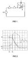
- the device shown has a DC voltage source UQ emitting a supply voltage, a resistor R connected to the positive pole of the voltage source UQ, a coil L connected in series with the resistor R, a switch S which is formed by a relay and arranged between the coil L and the negative pole of the voltage source UQ, and a Zener diode Z connected in parallel with the switch S.
- the arrangement moreover contains a magnet which generates a magnetic field in the region of the contact elements C.
- the lines of flux of this magnetic field run perpendicular to the direction along which an arc may be formed.
- This magnetic field is designated by the reference symbol B in Figure 1, however, the magnet itself is not illustrated in Figure 1.
- the magnet is preferably a permanent magnet, for example a neodymium iron boron magnet or a samarium cobalt magnet. Alternatively, it would also be possible to use an electromagnet.
- the magnet, or to be more precise the magnetic field B generated thereby, and the Zener diode Z co-operate to ensure that an arc forming between the contact elements is extinguished rapidly. Once the arc has been extinguished, spark-over damaging or destroying the contact elements is controlled between the contact elements. Once the arc has been extinguished, damage or destruction of other parts of the system containing the arrangement is eliminated.
- An arc between the contact elements C can occur when the contact elements C are disengaged, but in some circumstances also when they are brought together. If, as in the embodiment under consideration, a DC voltage is supplied and no suitable measures are taken to prevent it, this arc is sustained for a considerable period of time and may damage or destroy the contact elements. Arcs of this type can be expected with DC voltages from around 14 V; however, they may also occur if the system containing the arrangement described includes an inductor even at lower voltages.
- the magnet operates as a device which is used to influence an arc forming between the contact elements C such that the voltage established between the contact elements is increased.
- this voltage will be around 16 V, regardless of the contact spacing.
- a strong magnetic field can increase this voltage by a multiple. If, as in the example under consideration, the system containing the arrangement has an inductor and/or parasitic inductors, which is virtually always the case, the voltage established between the contact elements will even increase to a level which may be more or less far above the voltage to be supplied through the arrangement, which in the embodiment under consideration is the 42-volt supply voltage from the voltage source UQ.
- an arc forming between the contact elements C may also be influenced in another way than by a magnet such that the voltage established between the contact elements is increased.
- the Zener diode Z operates as a quenching device which derives and/or consumes energy supplied to the contact elements C once a predetermined voltage is reached. This diverts the energy which the arc would need to be sustained and which once the arc has been extinguished can bring about spark-over between the contact elements.
- the contact elements C have a diameter of approximately 2 to 3 mm, the contact elements C are at a spacing of approximately 0.1 to 0.4 mm when disengaged from one another, the DC voltage passed through the contact elements C is 42 V, and the aim is to extinguish an arc forming between the contact elements C within 1 ms.
- the coil L has an inductance of 10 mH, the spacing between the disengaged contact elements C is 0.15 mm, and the flux density of the magnetic field B is 190 mT.
- the switch S is initially closed, at time T1. In this condition:
- the current flowing through the Zener diode Z has the effect that:
- the Zener diode consumes 97% of the energy which was stored in the coil L at the time of the switch S opening. It should be clear that under these circumstances neither the contact elements nor other parts of the system containing the arrangement can be damaged or destroyed.
- the consumption and/or diversion of the energy supplied to the contact elements by the quenching element proves to be advantageous in a number of ways.
- the brief period of existence of the arc moreover has the positive effect that the arrangement emits less electromagnetic interference.
Landscapes
- Arc-Extinguishing Devices That Are Switches (AREA)
- Switch Cases, Indication, And Locking (AREA)
- Contacts (AREA)
Abstract
Description
- providing multiple contacts, for example providing an arrangement in which two contact points can be connected and disconnected by way of a bridge,
- constructing the contacts within a vacuum chamber,
- filling the contact area with a particular and/or pressurised gas, and
- displacing the arc for example by use of a magnetic field or air flow away from the contact elements onto divergent electrical conductors which are connected to the contact elements. Additionally, where appropriate, providing arc-quenching plates between these conductors.
- the line UC shows the time curve of the voltage established between the contact elements C,
- the line IZ shows the time curve of the current flowing through the Zener diode Z, and
- the line IN shows the time curve of the current flowing through the circuit supplied with energy by way of the switch S.
- the spacing between two adjacent horizontal grid lines corresponds to 20 V for line UC; 2.3 A for line IZ; and 2.7 A for line IN, and
- the spacing between two adjacent vertical grid lines corresponds to 500 µs.
- the voltage UC between the contact elements C is 0 V,
- the current IZ flowing through the Zener diode Z is 0 A, and
- the current IN flowing through the circuit supplied with energy by way of the switch S is the current required by the consuming elements present therein.
- first an arc is formed between the contact elements C, which begins with a gradual increase in the voltage UC established between the contact elements,
- the current IZ flowing through the Zener diode Z remains at 0 A, and
- the current IN flowing through the circuit supplied with energy by way of the switch S falls slightly.
- the voltage UC established between the contact elements C leaps abruptly as a result of the magnetic field B acting on the arc, and in so doing exceeds the voltage from which the Zener diode Z passes into the conductive condition,
- the current IZ flowing through the Zener diode increases abruptly, and
- the current IN flowing through the circuit supplied with energy by way of the switch S falls more sharply than before.
- the arc is extinguished, and
- the voltage UC established between the contact elements C initially rises less steeply, then drops again, falling below the Zener voltage.
- the Zener diode Z passes into the blocking condition,
- the voltage UC established between the contact elements C passes transiently to the voltage emitted by the voltage source UQ, and
- the current IN flowing through the circuit supplied with energy by way of the switch S passes transiently to 0 A.
Claims (15)
- An arrangement having a contact element which can be brought into contact with another contact element, characterised in that the arrangement contains a device by means of which influence is exerted on an arc forming between the contact elements (C) in such a way that the voltage (UC) established between the contact elements is increased, and in that a quenching device (Z) is provided which diverts and/or consumes energy supplied to the contact elements once a predetermined voltage is reached.
- An arrangement according to Claim 1, characterised in that the device through which the arc forming between the contact elements (C) is influenced is a magnet which is arranged and constructed such that it generates a magnetic field (B) running transversely in relation to the arc in the region in which the arc forms.
- An arrangement according to Claim 2, characterised in that the magnetic field (B) is so strong that within an extremely brief period after the arc has arisen an abrupt increase in the voltage (UC) established between the contact elements (C) is produced.
- An arrangement according to Claim 3, characterised in that the magnetic field (B) is so strong that the abrupt increase in the voltage (UC) established between the contact elements (C) is produced within 1 ms of the arc arising.
- An arrangement according to Claim 2 to 4, characterised in that a magnet is used which generates a magnetic field (B) having a flux density of 100 mT or more in the region of the contact elements (C).
- An arrangement according to one of the preceding claims, characterised in that the predetermined voltage from which the quenching device (Z) consumes or diverts energy supplied to the contact elements (C) is higher than the voltage which is established in the steady state when the contact elements are disengaged from one another and when there is no arc between the contact elements.
- An arrangement according to Claim 6, characterised in that the predetermined voltage from which the quenching device (Z) consumes or diverts energy supplied to the contact elements (C) is only slightly higher than the voltage which is established in the steady state when the contact elements are disengaged from one another and when there is no arc between the contact elements.
- An arrangement according to one of the preceding claims, characterised in that the quenching device (Z) is arranged and constructed such that a current (IZ) flows by way of it in the event of voltages lying above the predetermined voltage, and no current flows in the event of voltages lying below the predetermined voltage.
- An arrangement according to one of the preceding claims, characterised in that the quenching device (Z) is a Zener diode.
- An arrangement according to Claim 9, characterised in that the Zener diode (Z) is provided in parallel with the contact elements (C).
- An arrangement according to one of the preceding claims, characterised in that the arrangement is also used in systems in which the voltage (UC) in the steady state with contact elements (C) not connected to one another, established between the latter, lies below the threshold value from which the formation of an arc is to be expected.
- An arrangement according to one of the preceding claims, characterised in that the contact elements (C) to be brought into contact are part of a switch.
- An arrangement according to one of the preceding claims, characterised in that the contact elements (C) to be brought into contact are part of a relay or a contactor.
- An arrangement according to one of the preceding claims, characterised in that the contact elements (C) to be brought into contact are part of electrical connectors to be connected to one another.
- An arrangement according to one of the preceding claims, characterised in that a direct current or a low-frequency alternating current flows by way of the contact elements (C) to be brought into contact in the mutually connected condition.
Applications Claiming Priority (2)
| Application Number | Priority Date | Filing Date | Title |
|---|---|---|---|
| DE10032650 | 2000-07-05 | ||
| DE10032650 | 2000-07-05 |
Publications (2)
| Publication Number | Publication Date |
|---|---|
| EP1170762A2 true EP1170762A2 (en) | 2002-01-09 |
| EP1170762A3 EP1170762A3 (en) | 2004-08-25 |
Family
ID=7647863
Family Applications (1)
| Application Number | Title | Priority Date | Filing Date |
|---|---|---|---|
| EP01116018A Withdrawn EP1170762A3 (en) | 2000-07-05 | 2001-07-02 | Arrangement having a contact element which can be brought into contact with another contact element |
Country Status (3)
| Country | Link |
|---|---|
| US (1) | US20020018332A1 (en) |
| EP (1) | EP1170762A3 (en) |
| JP (1) | JP2002063822A (en) |
Cited By (1)
| Publication number | Priority date | Publication date | Assignee | Title |
|---|---|---|---|---|
| US8619395B2 (en) | 2010-03-12 | 2013-12-31 | Arc Suppression Technologies, Llc | Two terminal arc suppressor |
Families Citing this family (3)
| Publication number | Priority date | Publication date | Assignee | Title |
|---|---|---|---|---|
| US6659783B2 (en) * | 2001-08-01 | 2003-12-09 | Tyco Electronics Corp | Electrical connector including variable resistance to reduce arcing |
| KR101214007B1 (en) | 2011-12-19 | 2012-12-20 | 공주대학교 산학협력단 | Direct current breaker using arc extinguishing device |
| JP5946382B2 (en) | 2012-09-21 | 2016-07-06 | 富士通コンポーネント株式会社 | Electromagnetic relay |
Family Cites Families (3)
| Publication number | Priority date | Publication date | Assignee | Title |
|---|---|---|---|---|
| US4401870A (en) * | 1981-11-10 | 1983-08-30 | Hydro-Quebec | Modular suction-gas-cooled magnetic blast circuit breaker |
| US4420784A (en) * | 1981-12-04 | 1983-12-13 | Eaton Corporation | Hybrid D.C. power controller |
| DE3543804A1 (en) * | 1984-12-14 | 1986-06-19 | General Electric Co., Schenectady, N.Y. | Switch having arc commutation |
-
2001
- 2001-06-26 US US09/891,675 patent/US20020018332A1/en not_active Abandoned
- 2001-07-02 EP EP01116018A patent/EP1170762A3/en not_active Withdrawn
- 2001-07-03 JP JP2001201854A patent/JP2002063822A/en active Pending
Cited By (7)
| Publication number | Priority date | Publication date | Assignee | Title |
|---|---|---|---|---|
| US8619395B2 (en) | 2010-03-12 | 2013-12-31 | Arc Suppression Technologies, Llc | Two terminal arc suppressor |
| US9087653B2 (en) | 2010-03-12 | 2015-07-21 | Arc Suppression Technologies, Llc | Two terminal arc suppressor |
| US9508501B2 (en) | 2010-03-12 | 2016-11-29 | Arc Suppression Technologies, Llc | Two terminal arc suppressor |
| US10134536B2 (en) | 2010-03-12 | 2018-11-20 | Arc Suppression Technologies, Llc | Two terminal arc suppressor |
| US10748719B2 (en) | 2010-03-12 | 2020-08-18 | Arc Suppression Technologies, Llc | Two terminal arc suppressor |
| US11295906B2 (en) | 2010-03-12 | 2022-04-05 | Arc Suppression Technologies, Llc | Two terminal arc suppressor |
| US11676777B2 (en) | 2010-03-12 | 2023-06-13 | Arc Suppression Technologies, Llc | Two terminal arc suppressor |
Also Published As
| Publication number | Publication date |
|---|---|
| EP1170762A3 (en) | 2004-08-25 |
| US20020018332A1 (en) | 2002-02-14 |
| JP2002063822A (en) | 2002-02-28 |
Similar Documents
| Publication | Publication Date | Title |
|---|---|---|
| RU2668986C1 (en) | Switching device for conducting and interrupting electric currents | |
| CN106716579B (en) | Arc Control for Contactor Assemblies | |
| US9673004B1 (en) | Electrical switching apparatus, and arc chamber assembly and associated circuit protection method | |
| EP0102442A2 (en) | Active arc suppression circuit for direct current switches | |
| US9935400B1 (en) | Arc discharge prevention mechanism of socket | |
| KR101569195B1 (en) | DC circuit breaker using magnetic field | |
| US9406465B1 (en) | Polarity insensitive arc quench | |
| EP2637188B1 (en) | Arc chuteless DC current interruptor | |
| KR101214007B1 (en) | Direct current breaker using arc extinguishing device | |
| CN107533927A (en) | Contactor assembly | |
| KR20180028488A (en) | Interrupt device for interrupting direct current | |
| US20020018332A1 (en) | Arrangement having a contact element which can be brought into contact with another contact element | |
| JP2017201623A (en) | Arc moving device | |
| MX392879B (en) | HIGH VOLTAGE ELECTRICAL DISCONNECT DEVICE WITH ARC DEFLECTOR MAGNETIC ASSEMBLY. | |
| JP2004158331A (en) | Outlet of dc power supply | |
| KR20080033904A (en) | Electromechanical circuit breaker and current interruption method in the electromechanical circuit breaker | |
| US9331475B2 (en) | Core | |
| CN107799365A (en) | Bistable permanent magnetic three-phase breaker | |
| CN113178755B (en) | Overload protection connecting equipment for hardware power supply automatic control | |
| WO2001033686A3 (en) | Method for monitoring the effectiveness of a component of an electrical device during operation | |
| CN209104078U (en) | High-voltage DC contactor arc-control device | |
| CA3217090A1 (en) | A high voltage high current arc extinguishing contactor | |
| CN215869147U (en) | Dry node contactor capable of freely combining alarm modes | |
| RU2726162C1 (en) | Switching device with improved electric arc quenching performed using permanent magnets | |
| JP2015079664A (en) | Circuit breaker |
Legal Events
| Date | Code | Title | Description |
|---|---|---|---|
| PUAI | Public reference made under article 153(3) epc to a published international application that has entered the european phase |
Free format text: ORIGINAL CODE: 0009012 |
|
| AK | Designated contracting states |
Kind code of ref document: A2 Designated state(s): AT BE CH CY DE DK ES FI FR GB GR IE IT LI LU MC NL PT SE TR |
|
| AX | Request for extension of the european patent |
Free format text: AL;LT;LV;MK;RO;SI |
|
| PUAL | Search report despatched |
Free format text: ORIGINAL CODE: 0009013 |
|
| AK | Designated contracting states |
Kind code of ref document: A3 Designated state(s): AT BE CH CY DE DK ES FI FR GB GR IE IT LI LU MC NL PT SE TR |
|
| AX | Request for extension of the european patent |
Extension state: AL LT LV MK RO SI |
|
| 17P | Request for examination filed |
Effective date: 20050111 |
|
| AKX | Designation fees paid |
Designated state(s): DE FR GB IT |
|
| RBV | Designated contracting states (corrected) |
Designated state(s): DE FR GB IT |
|
| STAA | Information on the status of an ep patent application or granted ep patent |
Free format text: STATUS: THE APPLICATION IS DEEMED TO BE WITHDRAWN |
|
| 18D | Application deemed to be withdrawn |
Effective date: 20061115 |