EP1170698A2 - Method and apparatus for improving signal to noise ratio using wavelet decomposition and frequency thresholding - Google Patents
Method and apparatus for improving signal to noise ratio using wavelet decomposition and frequency thresholding Download PDFInfo
- Publication number
- EP1170698A2 EP1170698A2 EP01110360A EP01110360A EP1170698A2 EP 1170698 A2 EP1170698 A2 EP 1170698A2 EP 01110360 A EP01110360 A EP 01110360A EP 01110360 A EP01110360 A EP 01110360A EP 1170698 A2 EP1170698 A2 EP 1170698A2
- Authority
- EP
- European Patent Office
- Prior art keywords
- signal
- level
- frequency
- wavelet
- thresholded
- Prior art date
- Legal status (The legal status is an assumption and is not a legal conclusion. Google has not performed a legal analysis and makes no representation as to the accuracy of the status listed.)
- Granted
Links
Images







Classifications
-
- G—PHYSICS
- G06—COMPUTING OR CALCULATING; COUNTING
- G06T—IMAGE DATA PROCESSING OR GENERATION, IN GENERAL
- G06T5/00—Image enhancement or restoration
- G06T5/10—Image enhancement or restoration using non-spatial domain filtering
-
- G—PHYSICS
- G06—COMPUTING OR CALCULATING; COUNTING
- G06T—IMAGE DATA PROCESSING OR GENERATION, IN GENERAL
- G06T5/00—Image enhancement or restoration
- G06T5/70—Denoising; Smoothing
-
- G—PHYSICS
- G06—COMPUTING OR CALCULATING; COUNTING
- G06T—IMAGE DATA PROCESSING OR GENERATION, IN GENERAL
- G06T2207/00—Indexing scheme for image analysis or image enhancement
- G06T2207/20—Special algorithmic details
- G06T2207/20048—Transform domain processing
- G06T2207/20064—Wavelet transform [DWT]
Definitions
- the present invention is directed to a method and apparatus for improving the signal to noise ratio of an information carrying signal.
- an information carrying signal is produced.
- a few examples of such technologies are imaging with a camera or opto-electronic sensor, radio and television communications, and medical imaging with magnetic resonance.
- the usefulness of the information carrying signal is dependent on its clarity, and noise in the signal, which is an inevitable result of physical and electrical processes, places a limitation on such clarity.
- One type of approach, to which the present invention pertains uses a mathematical operator known as a wavelet transform.
- a wavelet transform it is well known that an electrical signal typically has an amplitude which varies with time, thus creating a frequency content in the signal.
- Certain types of information, for example, optical information also has a spatial variance, and such is frequently converted to a time context in the electrical signal which results from the detection of the optical information.
- the electrical signal may be processed in the frequency domain, for instance, with a simple filter, or in a higher mathematical order domain known as a transform domain.
- the Fourier transform is a commonly used transform domain.
- the wavelet transform domain possesses advantages over the Fourier domain because while the Fourier domain addresses only the frequency content of a signal, the wavelet transform places the frequency content within a spatial context.
- the wavelet transform is capable of producing improved signal to noise ratio as compared with the Fourier transform, including signals with sharper edges.
- the present invention uses frequency thresholding.
- the wavelet transform may be advantageously adapted to this approach since it has the capability of automatically classifying information according to frequencies.
- a method of improving the signal to noise ratio of an information carrying signal comprising the steps of,
- Figures 1 and 2 are two examples of the many diverse types of systems which produce information carrying signals containing noise, to which the present invention pertains.
- a radar transmitter (not shown) sends out pulses, and as the radar receiver antenna 2 is moved, reflected pulses are received coming from different directions, and are passed on to R.F. amplifier 4 for amplification. Since the received pulses are in the presence of noise, if the received pulses are too small, they will not be detected at the output, but will be lost in the noise.
- wavelet noise processor 6 performing in accordance with the teachings of the present invention is provided. An information carrying signal with improved signal to noise ratio can then be passed to mixer 8 wherein it is converted to an intermediate frequency (I.F.), and from there to I.F. amplifier 10 and scope 12, where the improved signal is displayed.
- I.F. intermediate frequency
- FIG. 2 Such a system is depicted in Figure 2, and is seen to include a sensor comprised of optics 14 and detector array 16, and imaging processor 18.
- Noise in an optical imaging system can manifest itself as blurring, fuzzy features edges, or complete obscuring of image features or of regions of the image.
- a television camera is an example of an optical imaging system, but systems having improved resolution which can view, display and/or record images from great distances (e.g. from outer space) are also possible, and will benefit from signal to noise improvement.
- Such systems are disclosed in co-pending Applications No. 08/763,610 and 09/081,842 filed on December 11, 1996 and May 20, 1998 respectively, which are in their entireties incorporated herein by reference.
- processor 18 in Figure 2 herein is a superresolution processor which is capable of providing resolution to beyond the cut-off frequency of optics 14.
- wavelet noise processor 20 is provided, for example, at the output of the detector array 16, to enhance the signal to noise ratio.
- a wavelet is a mathematical operator comprised of a transform pair, and there are different types of wavelets having different technical names, such as Daubechies 4, Daubechies 6, etc.
- the Daubechies 4 wavelet which may be utilized in the present invention, is shown in Figures 3A and 3B.
- the wavelet is seen to be comprised of the transform pair ⁇ and ⁇ , each being a predetermined waveform.
- ⁇ acts as a high pass filter while ⁇ acts as a low pass filter.
- the signal is simultaneously subjected to high pass and low pass filtering.
- the ⁇ function effectively takes a derivative of the signal, thus providing a matrix of values which represent the difference between adjacent values in a matrix of values comprising the original signal, and the resulting high frequency matrix of values is known as the scaling matrix.
- the ⁇ function effectively integrates or takes an average of adjacent values in the original signal matrix, and the resulting matrix of values is known as the wavelet coefficient matrix.
- each resulting matrix is half the size of the matrix of values representing the original signal in one dimension and the same size in the other dimension.
- both the wavelet scaling matrix (high frequency) and the wavelet coefficient matrix (low frequency) together are the same size as the matrix representing the original signal.
- the wavelet transform matrices have both frequency and spatial information related to the signal being detected.
- the detailed nature of the high pass and low pass filtering and of the resulting matrices is further explained in connection with later figures, but the invention is now explained in connection with the block diagram of Figure 4.
- the information carrying signal/image is first sampled and digitized, as indicated by block 20.
- a process known as wavelet decomposition is performed. That is, wavelet transforms are repeatedly taken in order to isolate high frequency components, which correspond to noise. More particularly, a 1st level wavelet transform of the signal is taken (block 22), and then a further wavelet transform (2nd level) is taken of the 1st level transform, and so on.
- transform content is primarily signal information, but by the time higher order transforms are computed, it is primarily high frequency components which are attributable to noise.
- the purpose of the wavelet decomposition is to isolate the high frequency content of the signal, since noise, but not information is generally present at such higher frequencies.
- this is accomplished by computing wavelet transforms up to the fifth level, but it is to be understood that the specific level may be varied while retaining the principle of the invention. Also, it is noted that the terms “high frequency” and “low frequency” as used herein do not refer to absolute values, but rather to relative high and low values as applied to the frequency content of the particular signal/noise combination being processed.
- Taking an inverse wavelet transform converts the wavelet transform back to a signal in the time domain, and taking successively lower order transforms restores the size of the signal or image.
- To take the inverse wavelet transform of a particular level it is necessary to use the scaling matrix and wavelet coefficient matrix for the level above.
- the noise information is contained only within the scaling matrix, dummy or "altered" wavelength coefficient matrices are constructed.
- the altered matrices are accomplished by setting all coefficients to zero, while retaining the size of the matrix to be the correct size for the transform level to it pertains.
- 1st, 2nd, 3rd, 4th and 5th level zero-filled wavelet coefficient matrices are constructed.
- the 4th level inverse wavelet transform is computed using the 5th level scaling matrix and the 5th level zero-filled wavelet coefficient matrix.
- the 3rd to 1st inverse wavelet transforms are computed, using for each level, the scaling matrix and the zero-filled wavelet coefficient matrix for the level above.
- the inverse wavelet transform for the level below the 1st level is computed using the 1st level scaling matrix and the 1st level zero-filled wavelet coefficient matrix.
- LEVEL 5 FREQUENCY THRESHOLDED IMAGE which corresponds to the noise segregated by the 5th level wavelet transform converted to the time domain.
- the LEVEL 5 THRESHOLDED IMAGE is subtracted from the original image in block 44 to produce a resultant signal, known as the LEVEL 5 DIFFERENCE IMAGE.
- This resultant signal has an improved signal to noise ratio as compared to the original image signal, since noise has been subtracted therefrom. This may be used as the final recovered signal, or it may be improved still further, as described below.
- the LEVEL 5 THRESHOLDED IMAGE may contain a small amount of residual image information (e.g. edge or corner data). This can be due to the fact that while the values in the scaling matrix of the level 5 wavelet transform are substantially attributable to noise, they may contain a small amount of image information since, in some cases it can be difficult to distinguish high frequency image information from noise.
- a lower level wavelet transform may be used for such purpose.
- such lower level is the 2nd level wavelet transform, although in other embodiments, different levels or combinations thereof may be empirically determined.
- the process of generating the compensating signal is represented by blocks 48, 50 and 52.
- a 1st level wavelet transform is computed using the 2nd level scaling matrix and the 2nd level zero-filled wavelet coefficient matrix.
- the inverse wavelet transform for the level below the 1st level is computed using the scaling matrix for the 1st level wavelet transform and the zero-filled wavelet coefficient matrix for the 1st level wavelet transform, thereby providing the compensating signal.
- the result is subtracted from the original image on a pixel by pixel basis, thereby providing an intermediate signal, known as the LEVEL 2 DIFFERENCE LEVEL IMAGE. This is added pixel by pixel to the LEVEL 5 DIFFERENCE IMAGE at block 52, thereby providing the improved LEVEL 2/5 DIFFERENCE IMAGE.
- a still further improvement is signal to noise ratio may be possible by incorporating the step of block 54.
- the LEVEL 5 THRESHOLDED IMAGE is added to the LEVEL 2/5 DIFFERENCE IMAGE. Due to a sign change which occurs each time a wavelet transform is computed, this has the effect of subtracting the noise again, which has been found to further enhance the signal to noise ratio. The result is the NOISE REDUCED IMAGE.
- the frequency thresholded signal (LEVEL 5 THRESHOLDED SIGNAL in Figure 4) is derived from a higher order wavelet transform by using altered wavelet coefficient matrices which are zero-filled.
- altered wavelet coefficient matrices which are zero-filled.
- different altered matrices can be employed.
- the following (or other specific altered matrices) may be used.
- An apparatus aspect of the invention may be implemented in a programmed computer 90, shown in Figure 18, which carries out the process described above and depicted in Figure 4.
- the instructions comprising a computer program may be stored on conventional storage media 92 such as magnetic diskettes or optical disks, which would be read by the computer 90, stored,in local memory and executed under the control of the computer.
- Figure 5 shows a reference scene having a bar target optically superimposed thereon so as to appear as if its on the ground.
- the reference scene includes grass 60, trees 62, and roads 64.
- Figure 6 shows the reference scene as imaged through actual optics having a cut-off frequency, wherein the system has a signal to noise ratio of 20 (includes only Gaussian noise). It is seen that most high frequency detail in the background is lost.
- Figure 7 is a close-up of the bar target region from the image of Figure 6.
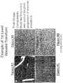
- Figures 8A to 8D depict matrix components of the 1st level wavelet transform of the reference scene. It should be noted that all matrix components are half the size of the original image in both the horizontal and vertical directions since the wavelet transform is taken in both directions.
- Figure 8A is the wavelet coefficient or low pass matrix while Figure 8B is the scaling or high pass matrix of vertical components.
- Figure 8C is the scaling matrix of horizontal components, while Figure 8D is the scaling matrix of diagonal components, i.e., the cross product of the horizontal and vertical components.
- Figures illustrate the frequency and spatial location properties of the wavelet transform.
- Figures 9A, 9B and 9C show a LEVEL 2 THRESHOLD IMAGE, a LEVEL 4 THRESHOLDED IMAGE, and a LEVEL 5 THRESHOLDED IMAGE, respectively, all formed with the D4 wavelet transform.
- the level 5 thresholded image has been previously discussed in connection with Figure 4, and it is comprised of noise, which when subtracted from the original image, improves the signal to noise ratio thereof.
- the LEVEL 2 THRESHOLDED IMAGE is mostly information content
- Figure 9B shows a LEVEL 4 THRESHOLDED IMAGE, seen to be intermediate the LEVEL 2 and LEVEL 5 THRESHOLDED IMAES in high frequency content.
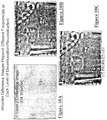
- FIGS 10A, 10B and 10C show a LEVEL 2 DIFFERENCE IMAGE, a LEVEL 4 DIFFERENCE IMAGE, and a LEVEL 5 DIFFERENCE IMAGE for the D4 wavelet transform, respectively. It will be observed that the LEVEL 4 DIFFERENCE IMAGE and the LEVEL 5 DIFFERENCE IMAGE are quite similar. These images have been corrected for noise, but appear to be somewhat low in contrast.
- Figure 11 illustrates how adding low frequency and high frequency images results in the desired recovered image. This is the step which is performed at block 54 of Figure 4, except that a LEVEL 2/4 DIFFERENCE IMAGE rather than a LEVEL 2/5 DIFFERENCE IMAGE is depicted in Figure 11.
- the resulting recovered image is corrected for noise and is of suitable contrast.
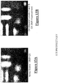
- Figure 13B shows a close-up of the bar target of Figure 12, which demonstrates a 5X signal to noise ratio improvement when compared with the close-up of the bar target of the noisy image of Figure 7 (shown in Figure 13A for purposes of comparison). This compares favorably with the improvements of 1x to 2.4 x obtained with the prior art heretofore discussed.
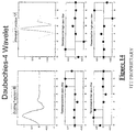
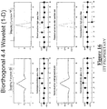
- Figure 14 shows the Daubechies 4 (D4) wavelet transform pair along with the equivalent decomposition and reconstruction low pass and high pass filters which correspond with the functions ⁇ and ⁇ , respectively. These are well known in the art and are included herein for the purpose of completeness.
- the original signal forms a matrix of values such as in a raster scan of an image having rows and columns of values. Each row and column of the signal is passed through the filters in turn in the following manner.
- the first eight values in a row or column are multiplied by the amplitude values corresponding to abscissa 0 to 7 in the low pass filter, i.e., the first signal value by the amplitude value for abscissa 0, the second signal value by the amplitude value for abscissa 1, and so forth. Then, a weighted average is taken, and the resulting value corresponds to the first value in the resulting transform matrix, and so forth for the remaining values.
- a set of differences between adjacent values is computed, and then weighted and combined as for the low pass filter.
- Figure 15 shows the same information for the Daubechies 6 (D6) wavelet transform
- Figure 16 shows this information for the biorthogonal 4.4 wavelet transform.
- Any of the other known wavelet transforms e.g. symmetric 8, may also be used.
- Certain wavelet transforms may be better suited to particular types of scenes, and in an apparatus according to the invention, the various wavelets would be stored, and either an operator would select the wavelet best suited for the scene, or such would be automatically accomplished by appropriate software.
- the system may also be made adaptive insofar as the specific wavelet levels which are employed, with certain levels (e.g. the 5th level as illustrated herein) providing best results with certain images, but other levels working better under different conditions and/or with different wavelet transforms.
- An advantage of the present invention is that it is capable of obviating Poisson noise as well as Gaussian noise.
- Poisson noise is difficult to deal with because it occurs as part of the detection process and varies with detected signal amplitude, while Gaussian noise is independent of signal amplitude.
- the sampling of the signal must take place at a time or spatial rate at least two times the maximum information frequency in the band-limited signal. For an audio sensor like a microphone, this means that a sample and hold/analog to digital converter which may be present at at least twice the maximum frequency that the preamplifier is capable of passing.
- a sample and hold/analog to digital converter must sample at at least twice the maximum frequency passed by the detector/IF/preamp stages. In the case of imaging, this means that there must be at least two detectors within the central spot of the diffraction pattern of the optical system. Under these circumstances, it can be seen that any signal detected by only one detector is higher than the highest information frequency in the signal, and must be noise, which is segregated by frequency thresholding. It is noted that when used in connection with the superresolution processor of Application No. 09/081,842 there would be at least five detectors with the central spot of the diffraction pattern of the optical system.
- a further advantage of the invention is that complex images and simple images gain the same benefit in the signal to noise ratio.
- the method and apparatus of the invention are robust over a large class of image types
- satellite-based imaging including satellites which are controlled from the earth, aircraft-based imaging, land-based long-range imaging, underwater imaging, infrared imaging of any type, sonar imaging, LIDAR imaging, laser back-scatter imaging, laser rangefinder accuracy enhancement, atmospheric sounding accuracy enhancement, radar imaging noise reduction, doppler-radar noise cancellation imaging such as X-ray, CAT-scan, PET-scan, MRI, ultrasound imaging, Doppler ultrasound imaging, thermal imaging, audio noise cancellation, automobile suspension vibration cancellation, radio noise cancellation, servo-loop noise reduction, mechanical vibration reduction, precision low noise test measurement, environmental background noise cancellation, seismic data analysis noise reduction, Very-Low-Frequency communication noise reduction, television signal enhancement, superresolution imaging preprocessing, radio-astronomy noise cancellation, astronomical instrument image noise cancellation, computer network communications signal enhancement, and Internet/Intranet communications signal enhancement.
- satellite-based imaging including satellites which are controlled from the earth, aircraft-based imaging, land-based long-range imaging, underwater imaging, infrared imaging of any type
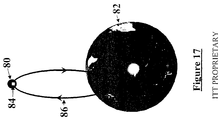
- Figure 17 shows a specific application of the invention as part of a satellite imaging system 84.
- a satellite imaging system 84 Such a system would generally be the type of imaging system heretofore described, land would incorporate a wavelet noise processor apparatus as described herein. It would be borne by satellite 80, which would orbit the earth 82, and provide images of selected targets on the earth.
- the satellite (including the imaging process) may be controlled by control means located on the earth via communications link 86. For example, the imaging dwell time, field-of-view, and spectral bands of interest may be selected and controlled from the earth, using computers with radio or laser links to the satellite.
Landscapes
- Physics & Mathematics (AREA)
- General Physics & Mathematics (AREA)
- Engineering & Computer Science (AREA)
- Theoretical Computer Science (AREA)
- Image Processing (AREA)
- Investigating Or Analyzing Materials By The Use Of Ultrasonic Waves (AREA)
- Noise Elimination (AREA)
Abstract
Description
Claims (49)
- A method of improving the signal to noise ratio of an information carrying signal, comprising the steps of:computing a wavelet transform of the information carrying signal up to a predetermined level,from the wavelet transform, deriving a frequency thresholded signal which is indicative of noise, andsubtracting the frequency thresholded signal from the information carrying signal to provide a resultant signal having an improved signal to noise ratio.
- The method of claims 1 wherein the wavelet transform at the predetermined level is comprised primarily of high frequency components which are attributable to noise.
- The method of claim 2 wherein the step of deriving a frequency thresholded signal which is indicative of noise includes computing an inverse wavelet transform.
- The method of claim 3 wherein each wavelet transform up to the predetermined level includes a wavelet scaling matrix which contains high frequencies and a wavelet coefficient matrix which contains low frequencies, and wherein the step of deriving a frequency thresholded signal includes constructing an altered wavelet coefficient matrix for each level up to the predetermined level.
- The method of claim 4 wherein the step of deriving a frequency thresholded signal further includes computing an inverse wavelet transform for each level below the predetermined level, down to the level below the first level, while using for the computation for each level the wavelet scaling matrix and the altered wavelet coefficient matrix corresponding to the level above.
- The method of claim 5 wherein the altered wavelet coefficient matrix has all coefficients set to zero.
- The method of claim 5 wherein the altered wavelet coefficient matrix has all coefficients set to a selected non-zero value.
- The method of claim 5 wherein the altered wavelet coefficient matrix has only coefficients below a predetermined amplitude threshold set to zero.
- The method of claim 5 wherein the predetermined level is the fifth level wavelet transform.
- The method of claim 3 further including the step of generating a compensating signal to compensate for information from the information carrying signal which may be present in the frequency thresholded signal.
- The method of claim 6 further including the step of providing a compensating signal to compensate for information from the information carrying signal which may be present in the frequency thresholded signal.
- The method of claim 10 wherein the step of providing a compensating signal comprises computing inverse wavelet transforms from a particular level which is below the predetermined level down to the level below the first level, while for the computation for each such level using the wavelet scaling matrix and the altered wavelet coefficient matrix corresponding to the level above.
- The method of claim 12 wherein the particular level below the predetermined level is the second level.
- The method of claim 12 wherein the compensation is accomplished by subtracting the compensating signal from the information carrying signal to provide an intermediate signal, and adding the intermediate signal to the resultant signal.
- The method of claim 3 further including the step of subtracting the frequency thresholded signal from the resultant signal.
- The method of claim 14 further including the step of subtracting the frequency thresholded signal from the resultant signal.
- The method of claim 3 wherein the wavelet transform at the predetermined level is comprised substantially of high frequency components which are attributable to noise.
- The method of claim 3 wherein the information carrying signal is obtained by sampling the information at at least two times the maximum frequency occurring in the information.
- The method of claim 6 wherein the information carrying signal is obtained by sampling the information at at least two times the maximum frequency occurring in the information.
- The method of claim 3 wherein the information carrying signal is derived from an image.
- The method of claim 19 wherein the information carrying signal is derived from an image.
- The method of claim 20 further including the step of selecting the predetermined level in dependence on the image.
- An apparatus for improving the signal to noise ratio of an information carrying signal, comprising,
a computer programmed to perform the steps of:
receiving the information carrying signal and computing a wavelet transform of such signal up to predetermined level,
deriving from the wavelet transform, a frequency thresholded signal which is indicative of noise, and
subtracting the frequency thresholded signal from the information carrying signal to provide a resultant signal having an improved signal to noise ratio. - The apparatus of claim 23 wherein the wavelet transform frequency at the predetermined level is comprised primarily of high frequency components which are attributable to noise.
- The apparatus of claim 24 wherein the step of deriving a frequency thresholded signal which is indicative of noise includes computing an inverse wavelet transform.
- The apparatus of claim 25 wherein each wavelet transform up to the predetermined level includes a wavelet scaling matrix which contains high frequencies and a wavelet coefficient matrix which contains low frequencies, and wherein the step of deriving a frequency thresholded signal includes constructing an altered wavelet coefficient matrix for each level up to the predetermined level.
- The apparatus of claim 26 wherein the step of deriving a frequency thresholded signal further includes computing an inverse wavelet transform for each level below the predetermined level, down to the level below the first level, while using for the computation for each level the wavelet scaling matrix and the altered wavelet coefficient matrix corresponding to the level above.
- The apparatus of claim 27 wherein the altered wavelet coefficient matrix has all coefficients set to zero.
- The apparatus of claim 27 wherein the altered wavelet coefficient matrix has all coefficients set to a predetermined non-zero value.
- The apparatus of claim 27 wherein altered wavelet coefficient matrix has only coefficients below a selected amplitude threshold set to zero.
- The apparatus of claim 28 wherein the predetermined level is the fifth level wavelet transform.
- The apparatus of claim 25 wherein the computer is programmed to perform the step of generating a compensating signal to compensate for information from the information carrying signal which may be present in the frequency thresholded signal.
- The apparatus of claim 28 wherein the computer is further programmed to perform the step of generating a compensating signal to compensate for information from the information carrying signal which may be present in the frequency thresholded signal.
- The apparatus of claim 32 wherein the computer is programmed to generate the compensating signal by computing inverse wavelet transforms from a particular level which is below the predetermined level down to the level below the first level, while for the computation for each such level using the wavelet scaling matrix and the altered wavelet coefficient matrix corresponding to the level above.
- The apparatus claim 34 wherein the particular level below the predetermined level is the second level.
- The apparatus of claim 32 wherein the computer is programmed to subtract the compensating signal from the information carrying signal to produce an intermediate signal, and to add the intermediate signal to the resultant signal.
- The apparatus of claim 25 wherein the computer is further programmed to subtract the frequency thresholded signal from the resultant signal.
- The apparatus of claim 36 wherein the computer is further programmed to subtract the frequency thresholded signal from the resultant signal.
- The apparatus of claim 25 wherein the wavelet transform at the predetermined level is comprised substantially of high frequency components which are attributable to noise.
- The apparatus of claim 24 further including means for sampling the information carrying signal at at least two times the maximum frequency occurring in the information before the information carrying signal is received by the computer.
- The apparatus of claim 28 further including means for sampling the information carrying signal at at least two times the maximum frequency occurring in the information before the information carrying signal is received by the computer.
- The apparatus of claim 25 wherein the information carrying signal is an image signal.
- The apparatus of claim 41 wherein the information carrying signal is an image signal.
- The apparatus of claim 42 wherein the computer is arranged to select the predetermined level in dependence on the image.
- An imaging apparatus, comprising,means for sampling image information to provide an image signal,means for computing a wavelet transform of the image signal up to a predetermined level such that the transform is comprised primarily of high frequency components which are attributable to noise, wherein each wavelet transform includes a wavelet scaling matrix and a wavelet coefficient matrix,means for constructing altered wavelet coefficient matrices for each level up to the predetermined level,means for deriving a frequency thresholded signal by computing an inverse wavelet transform for each level below the predetermined level, down to the level below the first level, while using for the computation for each level the wavelet scaling matrix and the altered wavelet coefficient matrix corresponding to the level above, andmeans for subtracting the frequency thresholded signal from the image signal to provide an image signal having an improved signal to noise ratio.
- The apparatus of claim 45 wherein the means for sampling image information performs sampling at at least two times the maximum frequency occurring in the image information.
- The apparatus of claim 46 wherein the means for sampling includes a sensor comprising optics having a numerical aperture and detection means, wherein the detection means includes at least two detectors within the central spot of the diffraction pattern determined by the numerical aperture.
- The apparatus of claim 45 in combination with an orbiting satellite wherein the imaging apparatus is located on the satellite, and further comprising means located on the earth for controlling the satellite.
- A storage medium containing a set of instructions which can be implemented by a computer for performing the steps of,subtracting the frequency thresholded signal from the information carrying signal to provide a resultant signal having an improved signal to noise ratio.computing a wavelet transform of the information carrying signal up to a predetermined level,from the wavelet transform, deriving a frequency thresholded signal which is indicative of noise, and
Applications Claiming Priority (2)
| Application Number | Priority Date | Filing Date | Title |
|---|---|---|---|
| US09/563,453 US6741739B1 (en) | 2000-05-03 | 2000-05-03 | Method and apparatus for improving signal to noise ratio using wavelet decomposition and frequency thresholding |
| US563453 | 2000-05-03 |
Publications (3)
| Publication Number | Publication Date |
|---|---|
| EP1170698A2 true EP1170698A2 (en) | 2002-01-09 |
| EP1170698A3 EP1170698A3 (en) | 2003-09-17 |
| EP1170698B1 EP1170698B1 (en) | 2005-12-07 |
Family
ID=24250547
Family Applications (1)
| Application Number | Title | Priority Date | Filing Date |
|---|---|---|---|
| EP01110360A Expired - Lifetime EP1170698B1 (en) | 2000-05-03 | 2001-04-26 | Method and apparatus for improving signal to noise ratio using wavelet decomposition and frequency thresholding |
Country Status (4)
| Country | Link |
|---|---|
| US (1) | US6741739B1 (en) |
| EP (1) | EP1170698B1 (en) |
| DE (1) | DE60115546T2 (en) |
| HK (1) | HK1045392B (en) |
Cited By (6)
| Publication number | Priority date | Publication date | Assignee | Title |
|---|---|---|---|---|
| EP1922567A4 (en) * | 2005-07-28 | 2009-05-06 | Exxonmobil Upstream Res Co | Method for wavelet denoising of controlled source electromagnetic survey data |
| CN106384339A (en) * | 2016-09-30 | 2017-02-08 | 防城港市港口区高创信息技术有限公司 | Infrared night vision image enhancement method |
| CN113361427A (en) * | 2021-06-11 | 2021-09-07 | 温州大学 | WT and GA-PNN based composite power quality disturbance classification method |
| CN114486162A (en) * | 2022-02-11 | 2022-05-13 | 中国空气动力研究与发展中心计算空气动力研究所 | Sound signal separation method in wind tunnel acoustic measurement experiment |
| WO2024148665A1 (en) * | 2023-01-13 | 2024-07-18 | 宜宾市天珑通讯有限公司 | Resonance noise reduction method, system, and readable storage medium |
| CN118731958A (en) * | 2024-09-04 | 2024-10-01 | 南昌华安众辉健康科技股份有限公司 | A distance measurement method and system for laser medical equipment |
Families Citing this family (30)
| Publication number | Priority date | Publication date | Assignee | Title |
|---|---|---|---|---|
| US6975753B2 (en) * | 2000-09-13 | 2005-12-13 | Canon Kabushiki Kaisha | Image processing apparatus, image processing method, program for implementing said method, and storage medium therefor |
| JP4046969B2 (en) * | 2000-11-09 | 2008-02-13 | キヤノン株式会社 | Image processing apparatus, method thereof, program, and storage medium |
| US6891974B1 (en) * | 2001-01-08 | 2005-05-10 | Microsoft Corporation | System and method providing improved data compression via wavelet coefficient encoding |
| US7099417B2 (en) * | 2001-12-28 | 2006-08-29 | Agilent Technologies, Inc. | Trace video filtering using wavelet de-noising techniques |
| US7155007B1 (en) * | 2002-04-01 | 2006-12-26 | Verizon Corporate Services Group Inc. | Systems and methods for reducing noise in ADSL transmissions |
| US20040120549A1 (en) * | 2002-12-24 | 2004-06-24 | Chung-Shan Institute Of Science And Technology | Half-plane predictive cancellation method for laser radar distance image noise |
| US7548656B2 (en) * | 2003-01-16 | 2009-06-16 | Konica Minolta Holdings, Inc. | Method and apparatus for processing image signals by applying a multi-resolution conversion processing for reducing the image size and applying a dyadic wavelet transform |
| US7260272B2 (en) * | 2003-07-10 | 2007-08-21 | Samsung Electronics Co.. Ltd. | Method and apparatus for noise reduction using discrete wavelet transform |
| JP2006025591A (en) * | 2004-06-08 | 2006-01-26 | Toshiba Corp | Vehicle power supply |
| US7889943B1 (en) | 2005-04-18 | 2011-02-15 | Picture Code | Method and system for characterizing noise |
| US8059905B1 (en) | 2005-06-21 | 2011-11-15 | Picture Code | Method and system for thresholding |
| US8121848B2 (en) * | 2005-09-08 | 2012-02-21 | Pan Pacific Plasma Llc | Bases dictionary for low complexity matching pursuits data coding and decoding |
| US20070065034A1 (en) * | 2005-09-08 | 2007-03-22 | Monro Donald M | Wavelet matching pursuits coding and decoding |
| US7813573B2 (en) * | 2005-09-08 | 2010-10-12 | Monro Donald M | Data coding and decoding with replicated matching pursuits |
| US20070053603A1 (en) * | 2005-09-08 | 2007-03-08 | Monro Donald M | Low complexity bases matching pursuits data coding and decoding |
| US7848584B2 (en) * | 2005-09-08 | 2010-12-07 | Monro Donald M | Reduced dimension wavelet matching pursuits coding and decoding |
| EP1982305B1 (en) * | 2006-01-31 | 2011-06-15 | Canadian Space Agency | Method and system for increasing signal-to-noise ratio |
| US7911478B2 (en) * | 2006-08-28 | 2011-03-22 | Panasonic Corporation | Drawing device, drawing method, and drawing program |
| DE102007013570A1 (en) * | 2007-03-21 | 2008-09-25 | Siemens Ag | Method for noise reduction in digital images with locally different and directional noise |
| RU2343538C1 (en) * | 2007-10-31 | 2009-01-10 | Закрытое Акционерное Общество "Импульс" | Method for correction of digital x-ray images |
| US8538189B2 (en) * | 2008-11-14 | 2013-09-17 | Ati Technologies Ulc | Image noise filter and method |
| US8620978B2 (en) * | 2008-12-31 | 2013-12-31 | St. Jude Medical, Atrial Fibrillation Division, Inc. | System and method for filtering electrophysiological signals |
| EP2732437B1 (en) * | 2011-07-13 | 2017-09-06 | Rayvis GmbH | Transmission image reconstruction and imaging using poissonian detector data |
| KR20130064483A (en) * | 2011-12-08 | 2013-06-18 | 삼성전자주식회사 | Apparatus and method for processing medical image |
| US9552628B2 (en) * | 2014-03-12 | 2017-01-24 | Megachips Corporation | Image processor |
| US10249065B2 (en) | 2015-05-08 | 2019-04-02 | Max-Planck-Gesellschaft Zur Foerderung Der Wissenschaften E.V | Method and device for magnetic resonance imaging with improved sensitivity by noise reduction |
| CN114518563B (en) * | 2022-03-01 | 2022-09-09 | 国家卫星海洋应用中心 | Method for obtaining radar backscattering coefficient of satellite microwave scatterometer and corresponding device |
| CN116796130A (en) * | 2023-05-18 | 2023-09-22 | 江西飞尚科技有限公司 | Bridge vibration low-frequency reconstruction and denoising method, system, computer and storage medium |
| CN117184178B (en) * | 2023-09-08 | 2026-01-30 | 电子科技大学 | A Train Operation Status Monitoring Method Based on DAS Spatiotemporal Sequence Imagery |
| CN117893441B (en) * | 2024-03-15 | 2024-06-28 | 海南热带海洋学院 | Underwater ultrasonic image speckle noise suppression method based on block S transformation |
Family Cites Families (13)
| Publication number | Priority date | Publication date | Assignee | Title |
|---|---|---|---|---|
| US3953822A (en) | 1973-10-15 | 1976-04-27 | Rca Corporation | Wave-energy imaging technique |
| US4330833A (en) | 1978-05-26 | 1982-05-18 | Vicom Systems, Inc. | Method and apparatus for improved digital image processing |
| US4463381A (en) | 1980-04-16 | 1984-07-31 | Eastman Kodak Company | Image processing apparatus including a partitioned low pass channel |
| US5721694A (en) * | 1994-05-10 | 1998-02-24 | Aura System, Inc. | Non-linear deterministic stochastic filtering method and system |
| US5825936A (en) | 1994-09-22 | 1998-10-20 | University Of South Florida | Image analyzing device using adaptive criteria |
| US5619998A (en) * | 1994-09-23 | 1997-04-15 | General Electric Company | Enhanced method for reducing ultrasound speckle noise using wavelet transform |
| EP1168243B1 (en) * | 1995-09-29 | 2004-06-09 | Fuji Photo Film Co., Ltd. | Image processing method and apparatus |
| US5768474A (en) * | 1995-12-29 | 1998-06-16 | International Business Machines Corporation | Method and system for noise-robust speech processing with cochlea filters in an auditory model |
| GB2311431B (en) * | 1996-03-20 | 2000-02-23 | Sony Uk Ltd | Method and apparatus for deviding an input image into a plurality of images of different frequency bandwidths |
| US6240219B1 (en) * | 1996-12-11 | 2001-05-29 | Itt Industries Inc. | Apparatus and method for providing optical sensors with super resolution |
| US5867606A (en) * | 1997-08-12 | 1999-02-02 | Hewlett-Packard Company | Apparatus and method for determining the appropriate amount of sharpening for an image |
| US6069982A (en) * | 1997-12-23 | 2000-05-30 | Polaroid Corporation | Estimation of frequency dependence and grey-level dependence of noise in an image |
| US6295392B1 (en) * | 1998-05-20 | 2001-09-25 | Itt Manufacturing Enterprises, Inc. | Super resolution methods for electro-optical systems |
-
2000
- 2000-05-03 US US09/563,453 patent/US6741739B1/en not_active Expired - Fee Related
-
2001
- 2001-04-26 DE DE60115546T patent/DE60115546T2/en not_active Expired - Lifetime
- 2001-04-26 EP EP01110360A patent/EP1170698B1/en not_active Expired - Lifetime
-
2002
- 2002-07-09 HK HK02105109.5A patent/HK1045392B/en not_active IP Right Cessation
Cited By (7)
| Publication number | Priority date | Publication date | Assignee | Title |
|---|---|---|---|---|
| EP1922567A4 (en) * | 2005-07-28 | 2009-05-06 | Exxonmobil Upstream Res Co | Method for wavelet denoising of controlled source electromagnetic survey data |
| CN106384339A (en) * | 2016-09-30 | 2017-02-08 | 防城港市港口区高创信息技术有限公司 | Infrared night vision image enhancement method |
| CN113361427A (en) * | 2021-06-11 | 2021-09-07 | 温州大学 | WT and GA-PNN based composite power quality disturbance classification method |
| CN113361427B (en) * | 2021-06-11 | 2024-03-15 | 温州大学 | Composite electric energy quality disturbance classification method based on WT and GA-PNN |
| CN114486162A (en) * | 2022-02-11 | 2022-05-13 | 中国空气动力研究与发展中心计算空气动力研究所 | Sound signal separation method in wind tunnel acoustic measurement experiment |
| WO2024148665A1 (en) * | 2023-01-13 | 2024-07-18 | 宜宾市天珑通讯有限公司 | Resonance noise reduction method, system, and readable storage medium |
| CN118731958A (en) * | 2024-09-04 | 2024-10-01 | 南昌华安众辉健康科技股份有限公司 | A distance measurement method and system for laser medical equipment |
Also Published As
| Publication number | Publication date |
|---|---|
| HK1045392A1 (en) | 2002-11-22 |
| DE60115546T2 (en) | 2006-08-24 |
| EP1170698A3 (en) | 2003-09-17 |
| EP1170698B1 (en) | 2005-12-07 |
| HK1045392B (en) | 2006-10-13 |
| DE60115546D1 (en) | 2006-01-12 |
| US6741739B1 (en) | 2004-05-25 |
Similar Documents
| Publication | Publication Date | Title |
|---|---|---|
| US6741739B1 (en) | Method and apparatus for improving signal to noise ratio using wavelet decomposition and frequency thresholding | |
| Singh et al. | Analysis and effects of speckle noise in SAR images | |
| US7978926B2 (en) | Edge ringing artifact suppression methods and apparatuses | |
| EP1121607B1 (en) | Efficient multi-resolution space-time adaptive processor | |
| EP1982305B1 (en) | Method and system for increasing signal-to-noise ratio | |
| Schmitt | Multiscale and multidirectional multilooking for SAR image enhancement | |
| Sveinsson et al. | Almost translation invariant wavelet transformations for speckle reduction of SAR images | |
| CA2244574C (en) | Cepstral method and system for detecting/classifying objects | |
| Ali et al. | Design hybrid filter technique for mixed noise reduction from synthetic aperture radar imagery | |
| CN110517196B (en) | SAR image denoising method and system | |
| Devapal et al. | Object detection from SAR images based on curvelet despeckling | |
| Gupta | A review and comprehensive comparison of image denoising techniques | |
| Coltuc et al. | Time-space filtering of multitemporal SAR images | |
| Ye et al. | On linear and nonlinear processing of underwater, ground, aerial and satellite images | |
| Gleed et al. | High-speed super-resolution techniques for passive millimeter-wave imaging systems | |
| Prema et al. | A Comprehensive Analysis of Satellite Image Denoising using Earth Observation Data | |
| Ufade et al. | Comparison of spatial domain and transformation domain image fusion technique for restoration of blur images | |
| James et al. | Blind estimation of single look side scan sonar image from the observation model | |
| Lukin et al. | Adaptive nonlinear vector filtering of multichannel radar images | |
| Sanchez | A comparison of thresholding methods for two-dimensional wavelet-based image denoising: a thesis in Electrical Engineering | |
| Kumar et al. | Study of Synthetic Aperture Radar (SAR) Images Under the Purview of Speckle Noise Mitigation | |
| Kozaitis et al. | Speckle denoising using wavelet transforms and higher-order statistics | |
| Davey et al. | Infrared Speckle Observations of Binary Ross 614 AB: Combined Shift-and-Add and Zero-and-Add Analysis | |
| CommissionⅠ | WAVELET SPECKLE REDUCTION FOR SAR IMAGERY BASED ON EDGE DETECTION | |
| Lopes et al. | MODIS land cover product validation in the Iberian Peninsula |
Legal Events
| Date | Code | Title | Description |
|---|---|---|---|
| PUAI | Public reference made under article 153(3) epc to a published international application that has entered the european phase |
Free format text: ORIGINAL CODE: 0009012 |
|
| AK | Designated contracting states |
Kind code of ref document: A2 Designated state(s): AT BE CH CY DE DK ES FI FR GB GR IE IT LI LU MC NL PT SE TR |
|
| AX | Request for extension of the european patent |
Free format text: AL;LT;LV;MK;RO;SI |
|
| PUAL | Search report despatched |
Free format text: ORIGINAL CODE: 0009013 |
|
| RIC1 | Information provided on ipc code assigned before grant |
Ipc: 7G 06T 5/10 A Ipc: 7G 06T 5/00 B |
|
| AK | Designated contracting states |
Kind code of ref document: A3 Designated state(s): AT BE CH CY DE DK ES FI FR GB GR IE IT LI LU MC NL PT SE TR |
|
| AX | Request for extension of the european patent |
Extension state: AL LT LV MK RO SI |
|
| 17P | Request for examination filed |
Effective date: 20040317 |
|
| AKX | Designation fees paid |
Designated state(s): DE FR GB |
|
| 17Q | First examination report despatched |
Effective date: 20040609 |
|
| GRAP | Despatch of communication of intention to grant a patent |
Free format text: ORIGINAL CODE: EPIDOSNIGR1 |
|
| GRAS | Grant fee paid |
Free format text: ORIGINAL CODE: EPIDOSNIGR3 |
|
| GRAA | (expected) grant |
Free format text: ORIGINAL CODE: 0009210 |
|
| AK | Designated contracting states |
Kind code of ref document: B1 Designated state(s): DE FR GB |
|
| REG | Reference to a national code |
Ref country code: GB Ref legal event code: FG4D |
|
| REF | Corresponds to: |
Ref document number: 60115546 Country of ref document: DE Date of ref document: 20060112 Kind code of ref document: P |
|
| ET | Fr: translation filed | ||
| PLBE | No opposition filed within time limit |
Free format text: ORIGINAL CODE: 0009261 |
|
| REG | Reference to a national code |
Ref country code: HK Ref legal event code: GR Ref document number: 1045392 Country of ref document: HK |
|
| STAA | Information on the status of an ep patent application or granted ep patent |
Free format text: STATUS: NO OPPOSITION FILED WITHIN TIME LIMIT |
|
| 26N | No opposition filed |
Effective date: 20060908 |
|
| REG | Reference to a national code |
Ref country code: GB Ref legal event code: 732E Free format text: REGISTERED BETWEEN 20120906 AND 20120912 |
|
| REG | Reference to a national code |
Ref country code: FR Ref legal event code: CD Owner name: EXELIS INC., US Effective date: 20120912 Ref country code: FR Ref legal event code: TP Owner name: EXELIS INC., US Effective date: 20120912 |
|
| REG | Reference to a national code |
Ref country code: DE Ref legal event code: R081 Ref document number: 60115546 Country of ref document: DE Owner name: EXELIS INC., US Free format text: FORMER OWNER: ITT MANUFACTURING ENTERPRISES, INC., WILMINGTON, US Effective date: 20120913 Ref country code: DE Ref legal event code: R081 Ref document number: 60115546 Country of ref document: DE Owner name: EXELIS INC., MCLEAN, US Free format text: FORMER OWNER: ITT MANUFACTURING ENTERPRISES, INC., WILMINGTON, DEL., US Effective date: 20120913 |
|
| REG | Reference to a national code |
Ref country code: DE Ref legal event code: R082 Ref document number: 60115546 Country of ref document: DE Representative=s name: PATENTANWAELTE MAGENBAUER & KOLLEGEN PARTNERSC, DE Ref country code: DE Ref legal event code: R082 Ref document number: 60115546 Country of ref document: DE Representative=s name: PATENTANWAELTE MAGENBAUER & KOLLEGEN, DE |
|
| REG | Reference to a national code |
Ref country code: FR Ref legal event code: PLFP Year of fee payment: 15 |
|
| REG | Reference to a national code |
Ref country code: FR Ref legal event code: PLFP Year of fee payment: 16 |
|
| PGFP | Annual fee paid to national office [announced via postgrant information from national office to epo] |
Ref country code: DE Payment date: 20160427 Year of fee payment: 16 Ref country code: GB Payment date: 20160427 Year of fee payment: 16 |
|
| PGFP | Annual fee paid to national office [announced via postgrant information from national office to epo] |
Ref country code: FR Payment date: 20160425 Year of fee payment: 16 |
|
| REG | Reference to a national code |
Ref country code: DE Ref legal event code: R119 Ref document number: 60115546 Country of ref document: DE |
|
| GBPC | Gb: european patent ceased through non-payment of renewal fee |
Effective date: 20170426 |
|
| REG | Reference to a national code |
Ref country code: FR Ref legal event code: ST Effective date: 20171229 |
|
| PG25 | Lapsed in a contracting state [announced via postgrant information from national office to epo] |
Ref country code: DE Free format text: LAPSE BECAUSE OF NON-PAYMENT OF DUE FEES Effective date: 20171103 Ref country code: FR Free format text: LAPSE BECAUSE OF NON-PAYMENT OF DUE FEES Effective date: 20170502 |
|
| PG25 | Lapsed in a contracting state [announced via postgrant information from national office to epo] |
Ref country code: GB Free format text: LAPSE BECAUSE OF NON-PAYMENT OF DUE FEES Effective date: 20170426 |