EP1170599A1 - Perfectionnements aux systèmes d'observation et visée - Google Patents
Perfectionnements aux systèmes d'observation et visée Download PDFInfo
- Publication number
- EP1170599A1 EP1170599A1 EP01401770A EP01401770A EP1170599A1 EP 1170599 A1 EP1170599 A1 EP 1170599A1 EP 01401770 A EP01401770 A EP 01401770A EP 01401770 A EP01401770 A EP 01401770A EP 1170599 A1 EP1170599 A1 EP 1170599A1
- Authority
- EP
- European Patent Office
- Prior art keywords
- observation
- scanning
- active antenna
- supply
- sensors
- Prior art date
- Legal status (The legal status is an assumption and is not a legal conclusion. Google has not performed a legal analysis and makes no representation as to the accuracy of the status listed.)
- Granted
Links
- 230000003287 optical effect Effects 0.000 claims abstract description 10
- 229910000859 α-Fe Inorganic materials 0.000 claims abstract description 8
- 238000001514 detection method Methods 0.000 claims description 17
- 230000010363 phase shift Effects 0.000 claims description 4
- 238000005259 measurement Methods 0.000 claims description 3
- 230000004297 night vision Effects 0.000 claims description 3
- 230000005540 biological transmission Effects 0.000 claims description 2
- 230000003321 amplification Effects 0.000 abstract description 7
- 238000003199 nucleic acid amplification method Methods 0.000 abstract description 7
- 230000008901 benefit Effects 0.000 description 4
- 230000007704 transition Effects 0.000 description 4
- 230000005855 radiation Effects 0.000 description 3
- 230000010354 integration Effects 0.000 description 2
- 238000012544 monitoring process Methods 0.000 description 2
- 230000000630 rising effect Effects 0.000 description 2
- 238000011144 upstream manufacturing Methods 0.000 description 2
- 206010037180 Psychiatric symptoms Diseases 0.000 description 1
- 230000036626 alertness Effects 0.000 description 1
- 238000010304 firing Methods 0.000 description 1
- 230000007246 mechanism Effects 0.000 description 1
- 239000002184 metal Substances 0.000 description 1
- 238000000034 method Methods 0.000 description 1
- 230000005693 optoelectronics Effects 0.000 description 1
- 230000037361 pathway Effects 0.000 description 1
- 230000008569 process Effects 0.000 description 1
- 230000003252 repetitive effect Effects 0.000 description 1
- 238000004513 sizing Methods 0.000 description 1
Images


Classifications
-
- H—ELECTRICITY
- H01—ELECTRIC ELEMENTS
- H01Q—ANTENNAS, i.e. RADIO AERIALS
- H01Q23/00—Antennas with active circuits or circuit elements integrated within them or attached to them
-
- G—PHYSICS
- G01—MEASURING; TESTING
- G01S—RADIO DIRECTION-FINDING; RADIO NAVIGATION; DETERMINING DISTANCE OR VELOCITY BY USE OF RADIO WAVES; LOCATING OR PRESENCE-DETECTING BY USE OF THE REFLECTION OR RERADIATION OF RADIO WAVES; ANALOGOUS ARRANGEMENTS USING OTHER WAVES
- G01S7/00—Details of systems according to groups G01S13/00, G01S15/00, G01S17/00
- G01S7/02—Details of systems according to groups G01S13/00, G01S15/00, G01S17/00 of systems according to group G01S13/00
- G01S7/03—Details of HF subsystems specially adapted therefor, e.g. common to transmitter and receiver
- G01S7/032—Constructional details for solid-state radar subsystems
-
- H—ELECTRICITY
- H01—ELECTRIC ELEMENTS
- H01Q—ANTENNAS, i.e. RADIO AERIALS
- H01Q1/00—Details of, or arrangements associated with, antennas
- H01Q1/27—Adaptation for use in or on movable bodies
- H01Q1/28—Adaptation for use in or on aircraft, missiles, satellites, or balloons
-
- H—ELECTRICITY
- H01—ELECTRIC ELEMENTS
- H01Q—ANTENNAS, i.e. RADIO AERIALS
- H01Q3/00—Arrangements for changing or varying the orientation or the shape of the directional pattern of the waves radiated from an antenna or antenna system
- H01Q3/26—Arrangements for changing or varying the orientation or the shape of the directional pattern of the waves radiated from an antenna or antenna system varying the relative phase or relative amplitude of energisation between two or more active radiating elements; varying the distribution of energy across a radiating aperture
-
- H—ELECTRICITY
- H01—ELECTRIC ELEMENTS
- H01Q—ANTENNAS, i.e. RADIO AERIALS
- H01Q3/00—Arrangements for changing or varying the orientation or the shape of the directional pattern of the waves radiated from an antenna or antenna system
- H01Q3/26—Arrangements for changing or varying the orientation or the shape of the directional pattern of the waves radiated from an antenna or antenna system varying the relative phase or relative amplitude of energisation between two or more active radiating elements; varying the distribution of energy across a radiating aperture
- H01Q3/30—Arrangements for changing or varying the orientation or the shape of the directional pattern of the waves radiated from an antenna or antenna system varying the relative phase or relative amplitude of energisation between two or more active radiating elements; varying the distribution of energy across a radiating aperture varying the relative phase between the radiating elements of an array
- H01Q3/34—Arrangements for changing or varying the orientation or the shape of the directional pattern of the waves radiated from an antenna or antenna system varying the relative phase or relative amplitude of energisation between two or more active radiating elements; varying the distribution of energy across a radiating aperture varying the relative phase between the radiating elements of an array by electrical means
- H01Q3/36—Arrangements for changing or varying the orientation or the shape of the directional pattern of the waves radiated from an antenna or antenna system varying the relative phase or relative amplitude of energisation between two or more active radiating elements; varying the distribution of energy across a radiating aperture varying the relative phase between the radiating elements of an array by electrical means with variable phase-shifters
Definitions
- the present invention relates to observation and monitoring systems referred.
- such a system includes an optical unit for observation and aiming in the field of visible radiation, as well that different sensors such as an infrared camera, a television and a laser, in particular for night vision, deviation measurement, telemetry and / or target designation.
- sensors such as an infrared camera, a television and a laser, in particular for night vision, deviation measurement, telemetry and / or target designation.
- the line of sight of these different means is pivotally mounted in site and deposit in relation to the structure of the machine.
- observation and sighting systems known to date are particularly well suited to observation, recognition and identification, as well as firing and in general at most missions military.
- This permanent scanning is a repetitive operation, which can induce loss of attention in the user.
- a first solution to overcome this drawback is to work on the images recorded by the infrared camera a treatment of automatic detection, and complete the observation and sighting system by means of automatic tracking.
- This radar detection unit has the advantage of making it possible to correlate the detections carried out by the infrared camera and to mitigate the allocation of the range and contrast of infrared moisture detection means and bad weather conditions.
- the first idea that comes to mind to try to overcome this disadvantage is to split the angular orientation mechanisms of so as to allow radar scanning independent of infrared scanning.
- the invention proposes a solution which allows radar scanning independent of infrared scanning, while being of a size, weight and cost that allow it to be integrated easily in observation and sighting systems.
- the solution according to the invention is an observation and sighting system suitable for mounting on a vehicle, comprising detection means and / or radar observation, characterized in that these means include an active antenna and means which control electronically the supply of the various elementary antennas of said antenna active to scan the transmission / reception direction of said antenna around the viewing direction.
- the scanning is an angular scanning in deposit, but not on site.
- control means power supply then include MMIC amplifiers.
- MMIC amplifiers (Monolithic Microwave Integrated Circuits ”or monolithic microwave integrated circuits) are long used for their amplification function in other fields than observation and sighting systems (telecommunications in particular).
- the amplifiers MMICs have never been used to make active antennas, these generally using, in particular in the case of pulse radars, a single power source (traveling wave tube) whose output is divided to be distributed on the different elementary antennas which dials the active antenna.
- the active antennas known to date are generally antennas capable of scanning around two axes: the use of MMIC amplifiers on the different channels distributing the different elementary antennas of this type of antenna would lead to particularly complex solutions as to the size of the MMICs.
- the solution proposed here makes it possible to overcome this complexity using a scan around a single axis, which is particularly suitable for ground vehicles or helicopters or aircraft with a surveillance mission close to the ground.
- the invention also advantageously relates to a system observation or sighting for a vehicle comprising an optical unit for an observation and / or detection pathway in the visible and sensors for night vision and / or distance measurement and / or telemetry and / or the designation of targets, this optical unit and these sensors being mounted pivoting around at least one axis with respect to the vehicle, characterized in that it also includes a system of the aforementioned type.
- the radar detection and / or observation means are then advantageously arranged in the immediate vicinity of the optical unit and the sensors.
- An observation and sighting system conforming to a mode of possible realization of the invention comprises, in a manner known per se, a infrared camera, a built-in TV camera and laser, with a optical unit, in an aiming head.
- This aiming head also incorporates a radar detection unit.
- the radar detection unit comprises on the one hand an active antenna consisting of a plurality of elementary antennas juxtaposed and other share an electronics which controls the feeding of these different elementary antennas so that the main transmit / receive lobe of the active antenna performs an angular scan on either side of the sighting direction.
- the scanning carried out by this radar detection unit has the peculiarity of being an angular sweep around a single axis, the unit of radar detection not performing a field scan, but no site scanning.
- such an electronic scanning alone is particularly suitable for surveillance of distant targets by an H helicopter, or generally any other vehicle, located at low altitude or at ground.
- the helicopter is located at an altitude of around 50 m.
- Active antenna radar has an aperture angular in elevation of ⁇ 24 mrad on either side of the sighting direction. he performs a bearing scan of said sighting direction.
- the frequency of the sweep in a field is for example 0.25 Hz.
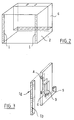
- the electronic scanning antenna shown in Figure 2 comprises a plurality of elementary antennas 1, which are distributed in the same plane and are parallel to each other.
- the plane in which these elementary antennas 1 are arranged is a plane perpendicular to the direction of sight of the radar.
- These elementary antennas are slot antennas (radiation on the short side), each consisting of two half-guides resonants 1a, 1b.
- resonant half guides 1a, 1b are supplied by via a control module 2 made up of a plurality supply elements 3 of the type shown in FIG. 3.
- the supply elements 3 are flat metal structures arranged parallel to each other others, each elementary antenna 1 being associated with a structure 3 and extending in the height of the edge thereof.
- the thickness of the elementary antennas 1 and of the structures 3 is chosen to obtain a minimum of side lobes in the radiation pattern in deposit.
- the arrangement of the slots is chosen so as to minimize site side lobes.
- each of these structures supply 3 has a housing 3a for receiving a module amplification and phase shift. It integrates waveguides 4, 5 allowing to connect said module on the one hand to the two half-waveguides resonants 1a, 1b associated with the structure (waveguides 4) and on the other hand to supply / distribution means upstream of said structure (means referenced by 6 in Figure 2) (waveguide 5).
- the amplification module 8 is advantageously a module with monolithic microwave integrated circuit or MMIC ("Monolithic microwave integrated circuits ”) according to the terminology generally used by the skilled person.
- This module is used as an upstream amplifier and as a low noise downstream preamplifier.
- the signals transmitted are for example pulse signals.
- Remote processing means are provided to process the echo signals received.
- control module 2 and the antennas 1 have a total size of 200 x 200 x 50 mm 3 and a weight of less than 2 Kg, which allows easy integration of the radar assembly into a head of referred.
Landscapes
- Engineering & Computer Science (AREA)
- Remote Sensing (AREA)
- Physics & Mathematics (AREA)
- General Physics & Mathematics (AREA)
- Radar, Positioning & Navigation (AREA)
- Astronomy & Astrophysics (AREA)
- Aviation & Aerospace Engineering (AREA)
- Computer Networks & Wireless Communication (AREA)
- Radar Systems Or Details Thereof (AREA)
- Variable-Direction Aerials And Aerial Arrays (AREA)
Abstract
Description
- les moyens de commande comportent des moyens de déphasage commandés, disposés sur le trajet des ondes émises, en aval des amplificateurs à MMIC ;
- ces moyens de déphasage sont du type à ferrite ;
- les moyens de détection et/ou d'observation radar sont du type à ondes millimétriques.
- les figures 1a et 1b sont des représentations schématiques en vue de côté et en vue de dessus illustrant la surveillance mise en oeuvre par un système d'observation et de visée conforme à un mode de réalisation de l'invention ;
- la figure 2 illustre schématiquement l'intégration d'un système à MMIC conforme à un mode de réalisation possible de l'invention ;
- la figure 3 illustre schématiquement un détail d'alimentation d'une antenne du système de la figure 2 ;
- la figure 4 illustre schématiquement la structure de module MMIC conforme à un mode de réalisation possible de l'invention.
- un circulateur 7 à deux branches, l'une pour les ondes montantes, l'autre pour les branches descendantes ;
- un module d'amplification 8,
- deux guides d'ondes 9 de transition, l'un pour les ondes montantes, l'autre pour les ondes descendantes,
- un déphaseur 10 à ferrite,
- un circulateur 11 relié à l'amplificateur MMIC, un circulateur de transition, des moyens de déphasage en ferrite, ainsi qu'un circulateur reliant ces moyens de déphasage à un guide d'ondes lui-même relié aux deux antennes.
Claims (10)
- Système d'observation et de visée apte à être monté sur un véhicule, comportant des moyens de détection et/ou d'observation radar, caractérisé en ce que ces moyens comportent une antenne active et des moyens qui commandent électroniquement l'alimentation des différentes antennes élémentaires de ladite antenne active pour réaliser un balayage de la direction d'émission/réception de ladite antenne autour de la direction de visée.
- Système selon la revendication 1, caractérisé en ce que le balayage est un balayage angulaire en gisement, mais pas en site.
- Système selon la revendication 2, caractérisé en ce que les moyens de commande d'alimentation comportent des amplificateurs à MMIC répartis sur les différentes voies d'alimentation des antennes élémentaires de l'antenne active.
- Système selon la revendication 3, caractérisé en ce que lesdits moyens de commande comportent des moyens de déphasage commandés, disposés sur le trajet des ondes émises, en aval des amplificateurs à MMIC.
- Système selon la revendication 4, caractérisé en ce que ces moyens de déphasage sont du type à ferrite.
- Système selon l'une des revendications 3 à 5, caractérisé en ce que les moyens de commande sont répartis sur des structures d'alimentation de forme générales plates et disposées de façon parallèle les unes aux autres dans un module de commande.
- Système selon la revendication 6, caractérisé en ce que les antennes élémentaires de l'antenne active s'étendent le long des tranches desdites structures.
- Système selon l'une des revendications précédentes, caractérisé en ce que les moyens de détection et/ou d'observation radar sont du type à ondes millimétriques
- Système d'observation ou de visée pour véhicule comportant un bloc optique pour une voie d'observation et/ou de détection dans le domaine du visible et des senseurs pour la vision de nuit et/ou l'écartométrie et/ou la télémétrie et/ou la désignation de cibles, ce bloc optique et ces senseurs étant montés pivotant autour d'au moins un axe par rapport au véhicule, caractérisé en ce qu'il comporte également un système selon l'une des revendications précédentes.
- Système selon la revendication 9, caractérisé en ce que les moyens de détection et/ou d'observation radar sont disposés à proximité immédiate du bloc optique et des senseurs.
Applications Claiming Priority (2)
| Application Number | Priority Date | Filing Date | Title |
|---|---|---|---|
| FR0008606A FR2811087B1 (fr) | 2000-07-03 | 2000-07-03 | Perfectionnements aux systemes d'observation et de visee |
| FR0008606 | 2000-07-03 |
Publications (2)
| Publication Number | Publication Date |
|---|---|
| EP1170599A1 true EP1170599A1 (fr) | 2002-01-09 |
| EP1170599B1 EP1170599B1 (fr) | 2004-03-03 |
Family
ID=8852035
Family Applications (1)
| Application Number | Title | Priority Date | Filing Date |
|---|---|---|---|
| EP20010401770 Expired - Lifetime EP1170599B1 (fr) | 2000-07-03 | 2001-07-03 | Perfectionnements aux systèmes d'observation et visée |
Country Status (4)
| Country | Link |
|---|---|
| EP (1) | EP1170599B1 (fr) |
| DE (1) | DE60102182T2 (fr) |
| ES (1) | ES2215116T3 (fr) |
| FR (1) | FR2811087B1 (fr) |
Cited By (1)
| Publication number | Priority date | Publication date | Assignee | Title |
|---|---|---|---|---|
| US20220229172A1 (en) * | 2021-01-19 | 2022-07-21 | Thales | Active antenna radar with extended angular coverage |
Citations (5)
| Publication number | Priority date | Publication date | Assignee | Title |
|---|---|---|---|---|
| EP0545742A1 (fr) * | 1991-10-31 | 1993-06-09 | Thomson-Csf | Procédé et dispositif de rejection des harmoniques émis par une antenne active à balayage électronique |
| US5471220A (en) * | 1994-02-17 | 1995-11-28 | Itt Corporation | Integrated adaptive array antenna |
| US5583511A (en) * | 1995-06-06 | 1996-12-10 | Hughes Missile Systems Company | Stepped beam active array antenna and radar system employing same |
| FR2751761A1 (fr) * | 1996-07-24 | 1998-01-30 | Sfim Ind | Systeme d'observation ou de visee |
| EP0987560A1 (fr) * | 1995-07-07 | 2000-03-22 | THE SECRETARY OF STATE FOR DEFENCE in Her Britannic Majesty's Gvmnt. of the United Kingdom of Great Britain & Northern Ireland | Module de circuit destiné à un radar à balayage électronique |
-
2000
- 2000-07-03 FR FR0008606A patent/FR2811087B1/fr not_active Expired - Fee Related
-
2001
- 2001-07-03 EP EP20010401770 patent/EP1170599B1/fr not_active Expired - Lifetime
- 2001-07-03 DE DE2001602182 patent/DE60102182T2/de not_active Expired - Fee Related
- 2001-07-03 ES ES01401770T patent/ES2215116T3/es not_active Expired - Lifetime
Patent Citations (5)
| Publication number | Priority date | Publication date | Assignee | Title |
|---|---|---|---|---|
| EP0545742A1 (fr) * | 1991-10-31 | 1993-06-09 | Thomson-Csf | Procédé et dispositif de rejection des harmoniques émis par une antenne active à balayage électronique |
| US5471220A (en) * | 1994-02-17 | 1995-11-28 | Itt Corporation | Integrated adaptive array antenna |
| US5583511A (en) * | 1995-06-06 | 1996-12-10 | Hughes Missile Systems Company | Stepped beam active array antenna and radar system employing same |
| EP0987560A1 (fr) * | 1995-07-07 | 2000-03-22 | THE SECRETARY OF STATE FOR DEFENCE in Her Britannic Majesty's Gvmnt. of the United Kingdom of Great Britain & Northern Ireland | Module de circuit destiné à un radar à balayage électronique |
| FR2751761A1 (fr) * | 1996-07-24 | 1998-01-30 | Sfim Ind | Systeme d'observation ou de visee |
Non-Patent Citations (2)
| Title |
|---|
| KOLE R F ET AL: "COBRA - LESSONS LEARNED", IEEE MTT-S INTERNATIONAL MICROWAVE SYMPOSIUM DIGEST,US,NEW YORK, IEEE, 23 May 1994 (1994-05-23), pages 1423 - 1426, XP000512766, ISBN: 0-7803-1779-3 * |
| LACOMME P ET AL: "AMSAR: A EUROPEAN ACTIVE ANTENNA RADAR PROGRAMME", PROCEEDINGS OF THE 1996 NATIONAL RADAR CONFERENCE,US,NEW YORK, IEEE, 13 May 1996 (1996-05-13), pages 82 - 87, XP000634922, ISBN: 0-7803-3147-8 * |
Cited By (2)
| Publication number | Priority date | Publication date | Assignee | Title |
|---|---|---|---|---|
| US20220229172A1 (en) * | 2021-01-19 | 2022-07-21 | Thales | Active antenna radar with extended angular coverage |
| US12241967B2 (en) * | 2021-01-19 | 2025-03-04 | Thales | Active antenna radar with extended angular coverage |
Also Published As
| Publication number | Publication date |
|---|---|
| FR2811087B1 (fr) | 2006-09-22 |
| FR2811087A1 (fr) | 2002-01-04 |
| DE60102182T2 (de) | 2005-02-24 |
| ES2215116T3 (es) | 2004-10-01 |
| DE60102182D1 (de) | 2004-04-08 |
| EP1170599B1 (fr) | 2004-03-03 |
Similar Documents
| Publication | Publication Date | Title |
|---|---|---|
| FR2651609A1 (fr) | Commande de pointage pour systeme d'antenne a balayage electronique et formation de faisceau par le calcul. | |
| EP0914620B1 (fr) | Systeme d'observation ou de visee | |
| FR2639718A1 (fr) | Radar ultrasonique a visee laterale notamment embarque dans un vehicule sous-marin se deplacant au-dessus d'une surface de visee | |
| WO2003046633A2 (fr) | Dispositif de veille optronique sectorielle ou panoramique a grande vitesse sans mouvement apparent | |
| EP1170599B1 (fr) | Perfectionnements aux systèmes d'observation et visée | |
| EP0638956B1 (fr) | Antenne active à balayage électronique en azimut et en élévation, en particulier pour l'imagerie hyperfréquence par satellite | |
| FR3115114A1 (fr) | Radar doppler a balayage electronique ambigu | |
| CA2840848C (fr) | Dispositif pour detecter des objets tels que des mines | |
| FR2985385A1 (fr) | Procede et systeme d'emission d'une onde electromagnetique radiofrequence | |
| FR2807509A1 (fr) | Dispositif de protection | |
| FR2657154A1 (fr) | Appareil de pointage monte sur casque. | |
| FR2767971A1 (fr) | Lentille d'antenne notamment pour un systeme de radar de vehicule automobile | |
| EP0638821B1 (fr) | Système d'imagerie radar hyperfréquence à double zone de couverture, destinée à être embarquée sur satellite | |
| FR2506445A1 (fr) | Procede et dispositif avertisseur de rayonnement laser ennemi | |
| EP1677385B1 (fr) | Antenne à balayage électronique large bande | |
| EP1233282B1 (fr) | Système à émission et réception réparties, notamment radar à émission synthétique et à formation de faisceau par le calcul | |
| FR2720515A1 (fr) | Instrument spatial d'observation laser, et véhicule spatial le comportant. | |
| FR2751420A1 (fr) | Systeme radar de surveillance a impulsions a antenne fixe | |
| EP0844495A1 (fr) | Dispositif de détection d'organes optiques pointés sur le dispositif | |
| FR2736731A1 (fr) | Dispositif de detection d'organes optiques pointes sur le dispositif | |
| FR2707386A1 (fr) | Système d'observation aérienne à drone captif. | |
| FR2903814A1 (fr) | Antenne a double alimentation | |
| FR3119027A1 (fr) | Radar à antenne active à couverture angulaire élargie | |
| EP0434476B1 (fr) | Projectile à basculement au devant et à proximité de la cible | |
| FR2654885A1 (fr) | Procede et installation de transmission de signal a large bande a partir d'un equipement mobile. |
Legal Events
| Date | Code | Title | Description |
|---|---|---|---|
| PUAI | Public reference made under article 153(3) epc to a published international application that has entered the european phase |
Free format text: ORIGINAL CODE: 0009012 |
|
| AK | Designated contracting states |
Kind code of ref document: A1 Designated state(s): DE ES FR Kind code of ref document: A1 Designated state(s): AT BE CH CY DE DK ES FI FR GB GR IE IT LI LU MC NL PT SE TR |
|
| AX | Request for extension of the european patent |
Free format text: AL;LT;LV;MK;RO;SI |
|
| 17P | Request for examination filed |
Effective date: 20020701 |
|
| AKX | Designation fees paid |
Free format text: DE ES FR |
|
| 17Q | First examination report despatched |
Effective date: 20030212 |
|
| GRAP | Despatch of communication of intention to grant a patent |
Free format text: ORIGINAL CODE: EPIDOSNIGR1 |
|
| GRAS | Grant fee paid |
Free format text: ORIGINAL CODE: EPIDOSNIGR3 |
|
| GRAA | (expected) grant |
Free format text: ORIGINAL CODE: 0009210 |
|
| AK | Designated contracting states |
Kind code of ref document: B1 Designated state(s): DE ES FR |
|
| REG | Reference to a national code |
Ref country code: IE Ref legal event code: FG4D Free format text: FRENCH |
|
| REF | Corresponds to: |
Ref document number: 60102182 Country of ref document: DE Date of ref document: 20040408 Kind code of ref document: P |
|
| REG | Reference to a national code |
Ref country code: ES Ref legal event code: FG2A Ref document number: 2215116 Country of ref document: ES Kind code of ref document: T3 |
|
| REG | Reference to a national code |
Ref country code: IE Ref legal event code: FD4D |
|
| PLBE | No opposition filed within time limit |
Free format text: ORIGINAL CODE: 0009261 |
|
| STAA | Information on the status of an ep patent application or granted ep patent |
Free format text: STATUS: NO OPPOSITION FILED WITHIN TIME LIMIT |
|
| 26N | No opposition filed |
Effective date: 20041206 |
|
| REG | Reference to a national code |
Ref country code: FR Ref legal event code: TP |
|
| PGFP | Annual fee paid to national office [announced via postgrant information from national office to epo] |
Ref country code: DE Payment date: 20080730 Year of fee payment: 8 Ref country code: ES Payment date: 20080718 Year of fee payment: 8 |
|
| PGFP | Annual fee paid to national office [announced via postgrant information from national office to epo] |
Ref country code: FR Payment date: 20080730 Year of fee payment: 8 |
|
| REG | Reference to a national code |
Ref country code: FR Ref legal event code: ST Effective date: 20100331 |
|
| PG25 | Lapsed in a contracting state [announced via postgrant information from national office to epo] |
Ref country code: FR Free format text: LAPSE BECAUSE OF NON-PAYMENT OF DUE FEES Effective date: 20090731 |
|
| PG25 | Lapsed in a contracting state [announced via postgrant information from national office to epo] |
Ref country code: DE Free format text: LAPSE BECAUSE OF NON-PAYMENT OF DUE FEES Effective date: 20100202 |
|
| REG | Reference to a national code |
Ref country code: ES Ref legal event code: FD2A Effective date: 20090704 |
|
| PG25 | Lapsed in a contracting state [announced via postgrant information from national office to epo] |
Ref country code: ES Free format text: LAPSE BECAUSE OF NON-PAYMENT OF DUE FEES Effective date: 20090704 |