EP1170469A1 - Dispositif d'entraínement linéaire d'une soupape au moyen d'aimants - Google Patents
Dispositif d'entraínement linéaire d'une soupape au moyen d'aimants Download PDFInfo
- Publication number
- EP1170469A1 EP1170469A1 EP01401654A EP01401654A EP1170469A1 EP 1170469 A1 EP1170469 A1 EP 1170469A1 EP 01401654 A EP01401654 A EP 01401654A EP 01401654 A EP01401654 A EP 01401654A EP 1170469 A1 EP1170469 A1 EP 1170469A1
- Authority
- EP
- European Patent Office
- Prior art keywords
- movable member
- drive device
- emi
- linear drive
- module
- Prior art date
- Legal status (The legal status is an assumption and is not a legal conclusion. Google has not performed a legal analysis and makes no representation as to the accuracy of the status listed.)
- Withdrawn
Links
Images



Classifications
-
- F—MECHANICAL ENGINEERING; LIGHTING; HEATING; WEAPONS; BLASTING
- F01—MACHINES OR ENGINES IN GENERAL; ENGINE PLANTS IN GENERAL; STEAM ENGINES
- F01L—CYCLICALLY OPERATING VALVES FOR MACHINES OR ENGINES
- F01L9/00—Valve-gear or valve arrangements actuated non-mechanically
- F01L9/20—Valve-gear or valve arrangements actuated non-mechanically by electric means
Definitions
- the present invention relates to a drive device linear.
- the present invention relates more particularly to a linear drive device along an axis, especially for driving a valve of an internal combustion engine, of the type comprising a fixed main unit delimiting a slot axial in which a movable member is guided in sliding axial from an extreme high position to an extreme position low, of the type comprising means for returning the member movable towards the high position, and of the type comprising means for locking the movable member, at least in its positions extremes.
- the electromagnetic actuators of valves have two springs, a valve spring and a actuator spring.
- the actuator body contains two electromagnets upper and lower which are likely to act on a pallet which is mounted on the upper end of the rod valve actuation.
- the control palette comes alternately stick on the upper electromagnets or lower when respectively closing or opening the valve.
- the arrangement of the two electromagnets means that, at the rest and under the action of the springs, the valve remains open balance position halfway.
- this type of actuator does not allow lifting partial of the valve.
- the invention aims to remedy these drawbacks.
- the invention provides a device of the type described above, characterized in that the fixed main unit has at least one module with at least one pair of magnets permanent, or source magnets, which are arranged opposite each side of the slot along an axis of magnetic attraction substantially perpendicular to the axis of movement and which have their poles oriented in the same direction along the axis of attraction magnetic, so as to form an air gap in the axial slot, and in that the movable member comprises at least one insert metallic associated with the air gap, the metallic insert being offset axially upward, relative to the air gap, when the member movable is in the high position, so that the movable member is driven from the high position to the low position under the effect of magnetic attraction, exerted by the field magnetic reigning in the air gap, on the metal insert.
- the vertical orientation of the axis of displacement A-A is not necessary for the operation of the device according to the invention.
- the axis of movement A-A could for example be horizontal, therefore perpendicular to the orientation of Earth's gravity.
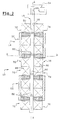
- FIGS. 1 and 2 show a device linear drive 10, along an axis of displacement A-A, of a valve 12 of a combustion engine.
- the drive device 10 includes a unit main fixed 14 which delimits a vertical slot 16 in which a movable member 18 is guided in vertical sliding by known guide means (not shown), between a position extreme high PH and an extreme low position PB.
- the fixed main unit 14 here comprises a module upper drive 20 and a drive module lower 22 substantially identical which are juxtaposed vertically and which act in series on the movable member 18.
- the drive device 10 also includes a locking actuator 24 of the movable member 18 in its extreme high PH and low PB positions, for example a piezoelectric type actuator.
- the movable member 18 here has the form of a plate substantially parallelepiped which globally defines a plane P containing the vertical axis of displacement A-A and containing an axis longitudinal C-C which is substantially perpendicular to the axis of displacement A-A.
- the longitudinal axis C-C is here perpendicular to the plane of the figure 2.
- the valve 12 is fixed to the lower axial end, along the axis of movement A-A, of the movable member 18.
- a known device 26 allowing the rotation of the valve 12 about its axis of movement A-A, is interposed between the valve 12 and the movable member 18.
- each module 20, 22 has an upper pair of magnets permanent 28, 30, or source magnets, and a lower pair source magnets 32, 34 which are vertically juxtaposed.
- Source magnets 28, 30, 32, 34 of a pair are arranged transversely on either side of the vertical slot 16, along a transverse axis of magnetic attraction B-B substantially perpendicular to the plane P.
- the different elements of the drive device 10 will be qualified as internal or external depending on their orientation in transverse direction B-B, respectively towards the slot 16 or towards the outside of the device 10.
- Source magnets 28, 30, 32, 34 of a pair are polarized in the same direction along the transverse axis of attraction magnetic B-B, so as to form a magnetic air gap EM of determined polarity in the axial slot 16.
- the two pairs of source magnets 28, 30, 32, 34 of a drive module 20, 22 are polarized in opposite directions.
- the source magnets 28, 30, 32, 34 each have a substantially parallelepiped shape and they each have an outer end surface 36 and an end surface internal 38 which are substantially parallel to the plane P.
- the source magnets 28, 30, 32, 34 are strong permanent magnets, e.g. earth-based rare, of the Neodyme-Fer-Bore type.
- a metal part 40, 42, 44, 46, or conductor of field, is interposed between the inner end surface 38 of each source magnet 28, 30, 32, 34 and the slot 16.
- Each field conductor 40, 42, 44, 46 has a outer end surface 48 and an inner end surface 50, or airgap surface, which are parallel to the plane P.
- the magnetic air gap EM formed by a pair of magnets sources 28, 30, 32, 34 is shown in Figure 4 as a zone delimited transversely by the airgap surfaces 50 of the field conductors 40, 42, 44, 46 opposite and delimited vertically by dotted lines of the height He air gap surfaces 50.
- the area of the outer end surface 48 of the field conductor 40, 42, 44, 46 adjacent to the source magnet associated 28, 30, 32, 34 is substantially equal to the area of the internal surface 38 of the associated source magnet 28, 30, 32, 34.
- the area of the outer end surface 48 of the field conductor 40, 42, 44, 46 is greater than the area of the air gap area 50, so that the field value magnetic B1 created by the associated source magnet 28, 30, 32, 34 at level of the airgap surface 50 is greater than that of the field B1 at the outer end surface 48 of the field conductor 40, 42, 44, 46.
- Each field conductor 40, 42, 44, 46 has here a vertical section, along the magnetic attraction axis B-B, generally trapezoidal isosceles, the smallest of the sides parallels of the trapezoid delimiting the airgap surface 50 and the most large parallel sides of the trapezoid defining the surface outer end 48.
- upper permanent magnets 52, 54, 56, 58 and below 60, 62, 64, 66 of concentration are adjacent to the surfaces, respectively upper 69 and lower 71, of each pair consisting of a source magnet 28, 30, 32, 34 and a field conductor 40, 42, 44, 46, for the purpose of reduce magnetic flux leakage ⁇ upwards and towards the down to concentrate the majority of the magnetic flux ⁇ in the air gap EM.
- Each concentration magnet 52, 54, 56, 58, 60, 62, 64, 66 has a substantially constant height along the conductor associated field 40, 42, 44, 46, then the height of each focus magnet 52, 54, 56, 58, 60, 62, 64, 66 decreases from the internal end surface 38 to the surface outer end 36 of the associated source magnet 28, 30, 32, 34.
- the concentration magnets 52, 54, 56, 58, 60, 62, 64, 66 are polarized in an orientation vertical substantially parallel to the axis of movement A-A.
- the magnets superiors of concentration 52, 56 are polarized from the top towards the bottom and the lower concentration magnets 60, 64 are polarized from the bottom up.
- the upper magnets of concentration 54, 58 are polarized from the bottom upwards and the lower concentration magnets 62, 66 are polarized from top to bottom.
- Source unit Usg, Usd, Uig, Uid each set consisting of a source magnet 28, 30, 32, 34, of its associated field conductor 40, 42, 44, 46 and its associated concentration magnets 52, 54, 56, 58, 60, 62, 64, 66.
- the source magnets 28, 30, 32, 34 which are juxtaposed vertically are magnetically connected by a plate external metallic connection 68, 70 which is parallel to the plane P and which is in contact with the outer end surfaces 36 of the two associated source magnets 28, 30, 32, 34.
- connection plates 68, 70 make it possible to close the magnetic circuit to reduce flux losses magnetic ⁇ .
- the upper left-hand unit Usg produces a magnetic flux ⁇ which crosses the upper air gap EMs, from left to right, which enters the source unit upper right Usd.
- the magnetic flux ⁇ then passes through the connecting plate right 70, from top to bottom, then it enters the source unit lower right Uid.
- the flow magnetic ⁇ crosses the lower air gap EMi, from right to left, and it enters the lower left source unit Uig.
- the magnetic flux ⁇ then passes through the connecting plate left 68, from bottom to top, and it enters the source unit upper left Usg.
- the magnetic flux ⁇ produced by each source unit Usg, Usd, Uig, Uid of a drive module 20, 22 describes a loop in the closed magnetic circuit of module 20, 22.
- Each source unit Usg, Usd, Uig, Uid of a module drive 20, 22 includes an electric coil 72, 74, 76, 78 which, when supplied with current, creates a field magnetic B2 whose orientation is substantially coaxial with the axis transverse magnetic attraction B-B of the source unit associated Usg, Usd, Uig, Uid.
- each coil electric 72, 74, 76, 78 is made up of wire windings around the source unit Usg, Usd, Uig, Uid corresponding.
- the windings form turns which are globally parallel to plane P.
- the current supply of the coils 72 is controlled, 74, 76, 78 via a control circuit (not represented).
- the four coils 72, 74, 76, 78 of the four source units Usg, Usd, Uig, Uid of a module 20, 22 are mounted in series so that, when an electric current is passed through the coils 72, 74, 76, 78, we decrease, or we increase, simultaneously the intensity of the magnetic field B1 produced by all the magnets sources 28, 30, 32, 34 associated with module 20, 22.
- the movable member 18 includes metal inserts longitudinal 80, 82, 84, 86, each metal insert 80, 82, 84, 86 being associated with an air gap EMs, EMi.
- a drive module 20, 22 correspond two metal inserts 80, 82, 84, 86 which are spaced vertically from a height Hi equal to that which separates vertically the transverse magnetic axes B-B of the two air gaps EMs, EMi juxtaposed with the module 20, 22.
- the metal inserts 80, 82, 84, 86 drive modules 20, 22 are vertically offset upwards with respect to the associated airgaps EMs, EMi, of so that at least the air gaps EMs, EMi of the upper module 20 exert, on the associated metal inserts 80, 82, a magnetic attraction force directed vertically downwards.
- axis. transverse mean of each metal insert 80, 82 associated with the upper module 20 is shifted vertically towards the high, in relation to the transverse magnetic axis B-B of the air gap EMs, associated EMi, the height of an air gap He, and the axis transverse mean of each metal insert 84, 86 associated with lower module 22 is shifted vertically upwards, by relation to the transverse magnetic axis B-B of the air gap EMs, EMi associated, of three heights of air gap He.
- the metal inserts 80, 82, 84, 86 are for example metal blades of the same height He as the air gaps associated EMs, EMi, and of the same transverse dimension as the transverse thickness Ep of the plate forming the movable member 18.
- the movable member 18 is made of a material generally insensitive to the magnetic attraction exerted by air gaps EMs, EMi, or non-magnetic material, for example in aluminum alloy or plastic.
- the movable member 18 is for example produced by bonding metal blades between aluminum alloy plates or well by molding plastic material on metal blades, so that the movable member 18 is of reduced mass.
- the metal inserts 80, 82, 84, 86 can be made by vertical stacking of sheet steel plates.
- This type of embodiment makes it possible to reduce the currents of Eddy which can cause harmful heating to correct operation of the device 10 and which are at the origin of losses, called iron losses, in device 10.
- the upper drive module 20 and the adjoining lower drive module 22 are in contact respectively by the lower surface 88 of the coils lower 76, 78 and by the upper surface 90 of the coils 72, 74.
- FIG. 5 shows a position of equilibrium stable magnetic PE of the movable member 18 in which the metallic inserts 80, 82 are placed in the air gaps EMs, Associated EMi of the drive module 20, thus closing the magnetic circuit created by the Usg, Usd, Uig, Uid source units associated.
- the movable member is shown in a high PH position, i.e. the metal inserts 80, 82 are vertically shifted upward relative to the air gaps EMs, EMi associated with the training module 20.
- the high PH position is an unstable position since the air gaps EMs, EMi exert, on the metal inserts 80, 82 associated, a downward magnetic attraction force which tends to drive the movable member 18 downward in order to recall towards its equilibrium position PE.
- the low position PB of the movable member 18, which is shown in Figure 6, is substantially symmetrical to the high PH position with respect to an average transverse axis of the training module 20.
- the metal inserts 80, 82 are therefore shifted vertically downwards with respect to associated air gaps EMs, EMi and the low position PB is therefore unstable, for the same reasons as those concerning high PH position.
- the magnetic attraction force is directed upwards here in order to recall the movable member 18 to its position of equilibrium EP.
- the movable member 18 When the movable member 18 is in the high PH position, if it is not blocked, it moves downward under the effect of the magnetic attraction exerted by the air gaps EMs, EMi.
- the movable member 18 Thanks to the kinetic energy it stores during its displacement, the movable member 18 exceeds the equilibrium position PE and descends approximately to the low position PB.
- the movable member 18 If the movable member 18 is not blocked in its position low PB, it then moves up, under the effect of the magnetic attraction exerted by the air gaps EMs, EMi.
- the movable member 18 exceeds the equilibrium position PE and rises approximately to the high PH position.
- each insert metallic 80, 82 of the movable member 18 is vertically offset, with respect to the transverse magnetic axis B-B of the air gap associated EMs, EMi, with a gap height He.
- the stroke of the movable member 18, between the high position PH and low position PB is approximately equal to two heights of air gap He.
- the blocking actuator 24 releases the member mobile 18.
- the module upper drive 20 causes the displacement of the organ movable 18 downwards, to a low position PB, relative to the upper module 20, or intermediate position PI, which is shown in Figure 9.
- the movable member 18 would stop in the intermediate position PI, before being called up, under the effect of attraction magnetic exerted by the air gaps EMs, EMi of the module upper 20 on the associated metallic inserts 80, 82.
- each insert metallic 80, 82 of the upper module 20 is offset vertically down from a gap height He, relative to the transverse magnetic axes B-B of the air gaps EMs, EMi associated, and the average transverse axis of each metal insert 84, 86 of the lower module 22 is offset axially upwards of a gap height He, relative to the magnetic axes cross-sections B-Bdes air gaps EMs, EMi associated.
- the intermediate position PI is therefore a position stable magnetic balance since, like the inserts metallic 80, 82, 84, 86 are located equidistant from their between EMs, respective EMi, the magnetic attraction force exerted upwards by the upper module 20 is equal to the magnetic attraction force exerted downwards by the module lower 22.
- the height which separates the inserts metallic 80, 82 of the upper module 20 of those 84, 86 of lower module 22 is such that when the movable member 18 is moved down by the upper module 20, the movable member 18 slightly exceeds the intermediate position PI downwards.
- the movable member 18 being shifted downwards by relative to the intermediate position PI, the air gaps EMs, EMi of the lower module 22 exert a magnetic attraction force directed downward which is greater than the force of attraction magnetic, directed upwards, exerted by the airgaps EMs, EMi of the upper module 20.
- the lower module 22 then "relays" the upper module 20 to drive the movable member 18 further down, according similar operation to the upper module 20.
- the movable member 18 then reaches its extreme low position PB, which is shown in Figure 10, in which the axis transverse mean of each metal insert 84, 86 of the module lower 22 is offset axially downward, relative to the axis magnetic B-B associated, with a gap height He, and in which the average transverse axis of each metal insert 80, 82 of the upper module 20 is offset axially downwards, by relative to the associated magnetic axis B-B, three heights air gap He.
- PB extreme low position
- the movable member 18 can be locked in this extreme low PB position by through the locking actuator 24.
- the movable member 18 can then be returned to its initial rest position, here the extreme position high PH, under the effect of magnetic forces exerted by drive modules 20, 22.
- the lower drive module 22 acts on the member mobile 18 to move it up to the position intermediate PI in which the upper drive module 20 "takes over” to drive the movable member 18 to the high PH position.
- the movable member 18 will therefore oscillate around the position intermediate PI then, the existence of friction will slow down gradually the movable member 18, which can no longer reach the high PH position and the low PB position and which will stabilize finally in its equilibrium position, i.e. here the position intermediate PI.
- the control of the coils 72, 74, 76, 78 allows in particular to accelerate the movement of the movable member 18.
- the upper module 20 is deactivated, in order to prevent it from produce an upwardly directed magnetic attraction force, which would slow down the movement of the movable member 18, and the lower module 22 is activated, which accelerates the movement from the movable member 18 to the low position PB.
- the linear drive device 10 includes known means (not shown) for determining the vertical position of the movable member 18, for example vertical position sensors.
- the restoring force of the movable member 18 can be produced by means of an elastic return member such as a compression or tension spring.
- the linear drive device 10 also allows, by appropriate control of the coils 72, 74, 76, 78, to maintain the movable member 18 in the position intermediate Pl, without using the locking actuator 24.
- the energy of displacement is provided mainly by the source magnets 28, 30, 32, 34 while, in the conventional electromagnetic actuators, the energy of displacement is provided by electromagnets which consume a significant amount of electrical energy.
- the amount of electrical energy necessary to operate the coils 72, 74, 76, 78 is very weak.
- the drive device 10 has also the advantage of consuming very little current electric to maintain the movable member 18, and therefore the valve 12, in its extreme positions PH, PB.
- the two drive modules 20, 22 we have an intermediate position PI for moving the movable member 18, which allows in particular, in the context of training a valve 12, to choose the opening height of the valve 12 with a view to optimally adapting it to each point of combustion engine operation.
- each drive module 20, 22 causes a displacement of the movable member 18 of twice the air gap height He.
- the total stroke of the movable member 18, in the drive device 10 with two modules 20, 22, is equal to four times the air gap height He.
- the drive device 10 also works with a single drive module 20, 22.
- the movable member 18 includes an insert additional metallic indexing 92 which is associated with the lower air gap EMi of the lower module 22.
- the metal indexing insert 92 is substantially symmetrical, relative to the lower air gap EMi, to the metal insert 86 normal associated with the lower air gap EMi of the lower module 22.
- the height of the metal indexing insert 92 is about twice the height He of a metal insert 80, 82, 84, 86 normal, i.e. two heights of air gap He, of so that, in the low position PB, the force of attraction magnetic exerted by the lower air gap EMi on the insert indexing metal 92, which points downwards, balances with the magnetic attraction force exerted by the air gaps EMs, EMi of the lower module 22 on the other inserts associated metal 84, 86, which is directed upwards, which keeps the movable member 18 in balance in the low position PB without the need to use a locking actuator 24.
- an electric current is circulated in the coils 72, 74, 76, 78 of the lower module 22 so that the upper coils 72, 74 of module 22 increase the intensity of the magnetic field B1 produced by the source units Usg, Usd, and so that the lower coils 76, 78 of module 22 decrease the intensity of the magnetic field B1 produced by the lower source units Uig, Uid.
Landscapes
- Engineering & Computer Science (AREA)
- Mechanical Engineering (AREA)
- General Engineering & Computer Science (AREA)
- Electromagnets (AREA)
- Valve Device For Special Equipments (AREA)
Abstract
Description
- chaque module d'entraínement comporte deux paires d'aimants sources qui sont superposées suivant l'axe de déplacement, chaque paire d'aimants sources étant associée à au moins un insert métallique distinct de l'organe mobile, de manière à agir en parallèle sur l'organe mobile ;
- les deux paires d'aimants sources sont polarisées en sens inverse ;
- de chaque côté de la fente, les deux aimants sources qui sont superposés axialement sont reliés magnétiquement par une pièce métallique, ou plaque, de liaison qui est en contact avec les deux aimants sources superposés ;
- chaque module d'entraínement comporte une pièce métallique, ou conducteur de champ, entre chaque aimant source et l'entrefer, en vue de conduire le flux magnétique produit par l'aimant jusqu'à l'entrefer ;
- chaque conducteur de champ comporte une surface interne, ou surface d'entrefer, qui délimite un côté de l'entrefer et une surface externe qui est adjacente à la surface interne de l'aimant source associé, et l'aire de la surface d'entrefer est inférieure à l'aire de la surface externe du conducteur de champ, en vue d'augmenter la valeur du champ magnétique au niveau de la surface d'entrefer par rapport à sa valeur au niveau de la surface externe associée ;
- chaque conducteur de champ comporte un aimant permanent supérieur de concentration qui est adjacent à la surface supérieure du conducteur de champ, l'aimant supérieur de concentration associé à l'aimant source polarisé de l'extérieur vers l'intérieur étant polarisé du haut vers le bas et l'aimant supérieur de concentration associé à l'aimant source polarisé de l'intérieur vers l'extérieur étant polarisé du bas vers le haut, en vue de diminuer les fuites de flux magnétique vers le haut ;
- chaque conducteur de champ comporte un aimant permanent inférieur de concentration qui est adjacent à la surface inférieure du conducteur de champ, l'aimant inférieur de concentration associé à l'aimant source polarisé de l'extérieur vers l'intérieur étant polarisé du bas vers le haut et l'aimant inférieur de concentration associé à l'aimant source polarisé de l'intérieur vers l'extérieur étant polarisé du haut vers le bas en vue de diminuer les fuites de flux magnétique vers le bas ;
- les aimants supérieur, et/ou inférieur, de concentration sont adjacents aux surfaces supérieures, respectivement inférieures, des aimants sources ;
- chaque unité-source, qui est constituée d'un aimant source et/ou du conducteur de champ associé, et d'aimants de concentration si le dispositif d'entraínement en comporte, comporte une bobine électrique qui est susceptible de produire un champ magnétique sensiblement coaxial à l'axe d'attraction magnétique de manière que, lorsque l'on fait circuler un courant électrique dans la bobine, et en fonction du sens de circulation, on diminue ou on augmente l'intensité du champ magnétique produit par l'aimant source associé dans l'entrefer correspondant ;
- les bobines d'un module d'entraínement sont montées en série de manière que, lorsque l'on fait circuler un courant électrique dans les bobines, on diminue, ou on augmente, simultanément l'intensité du champ magnétique produit par tous les aimants sources associés au module, c'est à dire que l'on désactive, respectivement on active, le module ;
- il comporte un circuit de commande de l'alimentation en courant des bobines des modules d'entraínement en vue de commander le blocage de l'organe mobile dans une position donnée ;
- l'organe mobile est susceptible d'être bloqué, au moins dans ses positions extrêmes, par un actionneur du type piézoélectrique ;
- l'organe mobile est rappelé vers sa position haute au moyen d'un organe élastique de rappel, par exemple un ressort de compression ou de traction ;
- l'organe mobile est rappelé vers sa position haute au moyen d'au moins un module d'entraínement qui entraíne l'organe mobile vers le haut sous l'effet de l'attraction magnétique exercée par au moins un entrefer sur l'insert métallique associé de l'organe mobile ;
- l'organe mobile est réalisé dans une matière globalement insensible à l'attraction magnétique exercée par les entrefers, par exemple en alliage d'aluminium ou en matière plastique ;
- l'organe mobile est une plaque sensiblement parallélépipédique qui définit un plan contenant l'axe de déplacement et un axe longitudinal, l'axe longitudinal étant sensiblement perpendiculaire à l'axe de déplacement et sensiblement perpendiculaire à l'axe d'attraction magnétique ;
- les inserts métalliques ont la forme de tiges, ou de lames, longitudinales ;
- les inserts métalliques sont réalisés par empilement axial, suivant l'axe de déplacement, de plaques de tôle d'acier, en vue de diminuer les courants de Foucault ;
- le dispositif comporte au moins deux modules d'entraínement agissant en série qui sont superposés axialement suivant l'axe de déplacement, un module supérieur et un module inférieur, les inserts métalliques associés aux entrefers du module inférieur étant décalés axialement, suivant l'axe de déplacement, vers le haut, de manière que, pendant le déplacement de l'organe mobile vers le bas, lorsque les inserts métalliques de l'organe mobile associés au module supérieur dépassent, sous l'effet de l'inertie de l'organe mobile, les entrefers correspondants, l'organe mobile continue d'être entraíné vers le bas, sous l'effet de l'attraction magnétique exercée par les entrefers du module inférieur sur les inserts métalliques associés ;
- l'organe mobile comporte un insert métallique d'indexation associé à l'entrefer d'un module d'entraínement, l'insert métallique d'indexation étant, dans une position donnée, sensiblement symétrique à l'insert métallique associé à l'entrefer, par rapport à l'entrefer, de manière que, lorsque l'organe mobile est dans la position donnée, la force d'attraction magnétique exercée par les entrefers sur les inserts métalliques associés de l'organe mobile s'équilibre avec la force d'attraction magnétique exercée par l'entrefer associé sur l'insert métallique d'indexation, en vue de maintenir l'organe mobile dans la position donnée, et de manière qu'une commande judicieuse des bobines des modules d'entraínement permette de sortir l'organe mobile de la position donnée ;
- il entraíne une soupape qui est fixée à l'extrémité axiale, suivant l'axe de déplacement, inférieure de l'organe mobile ;
- la soupape est montée à l'extrémité axiale inférieure de l'organe mobile - avec interposition d'un dispositif pour la rotation de la soupape autour de son axe de déplacement.
- la figure 1 est une vue en perspective avec arrachement qui représente un dispositif d'entraínement linéaire d'une soupape de moteur à combustion qui est réalisé conformément aux enseignements de l'invention ;
- la figure 2 est une vue en coupe par un plan vertical et transversal qui représente le dispositif d'entraínement linéaire selon l'invention ;
- la figure 3 est une vue agrandie similaire à la précédente qui représente le module supérieur d'entraínement ;
- la figure 4 est une vue agrandie similaire à la précédente qui représente l'entrefer magnétique supérieur du module supérieur d'entraínement ;
- les figures 5 à 7 sont des représentations schématiques d'un module d'entraínement lorsque l'organe mobile occupe respectivement une position d'équilibre magnétique, une position basse et une position haute ;
- les figures 8 à 10 sont des vues similaires à celles des figures 5 à 7 et elles représentent le dispositif d'entraínement linéaire selon l'invention lorsque l'organe mobile occupe respectivement une position extrême haute, une position intermédiaire, et une position extrême basse ;
- la figure 11 est une vue similaire à celles des figures 8 à 10 et elle représente un dispositif d'entraínement linéaire selon l'invention équipé d'un insert métallique d'indexation dans la position extrême basse.
Claims (23)
- Dispositif d'entraínement linéaire (10) selon un axe (A-A), notamment pour l'entraínement d'une soupape (12) d'un moteur à combustion interne, du type comportant une unité principale fixe (14) délimitant une fente axiale (16) dans laquelle un organe mobile (18) est guidé en coulissement axial depuis une position extrême haute (PH) vers une position extrême basse (PB), du type comportant des moyens de rappel (20, 22) de l'organe mobile (18) vers la position haute (PH), et du type comportant des moyens de blocage (20, 22, 24) de l'organe mobile (18), au moins dans ses positions extrêmes (PH, PB),
caractérisé en ce que l'unité principale fixe (14) comporte au moins un module d'entraínement (20, 22) équipé d'au moins une paire d'aimants permanents (28, 30, 32, 34), ou aimants sources, qui sont agencés en vis-à-vis de chaque côté de la fente (16) selon un axe d'attraction magnétique (B-B) sensiblement perpendiculaire à l'axe de déplacement (A-A) et qui ont leurs pôles orientés dans le même sens suivant l'axe d'attraction magnétique (B-B), de manière à former un entrefer (EMs, EMi) dans la fente axiale (16), et en ce que l'organe mobile (18) comporte au moins un insert métallique (80, 82, 84, 86) associé à l'entrefer (EMs, EMi), l'insert métallique (80, 82, 84, 86) étant décalé axialement (A-A) vers le haut, par rapport à l'entrefer (EMs, EMi), lorsque l'organe mobile (18) est en position haute (PH), de manière que l'organe mobile (18) soit entraíné depuis la position haute (PH) vers la position basse (PB) sous l'effet de l'attraction magnétique, exercée par le champ magnétique (B1, B2) régnant dans l'entrefer (EMs, EMi), sur l'insert métallique (80, 82, 84, 86). - Dispositif d'entraínement linéaire (10) selon la revendication précédente, caractérisé en ce que chaque module d'entraínement (20, 22) comporte deux paires d'aimants sources (28, 30, 32, 34) qui sont superposées suivant l'axe de déplacement (A-A), chaque paire d'aimants sources (28, 30, 32, 34) étant associée à au moins un insert métallique (80, 82, 84, 86) distinct de l'organe mobile (18), de manière à agir en parallèle sur l'organe mobile (18).
- Dispositif d'entraínement linéaire (10) selon la revendication précédente, caractérisé en ce que les deux paires d'aimants sources (28, 30, 32, 34) sont polarisées en sens inverse.
- Dispositif d'entraínement linéaire (10) selon la revendication précédente, caractérisé en ce que, de chaque côté de la fente (10), les deux aimants sources (28, 30, 32, 34) qui sont superposés axialement (A-A) sont reliés magnétiquement par une pièce métallique (68, 7û), ou plaque, de liaison qui est en contact avec les deux aimants sources superposés (28, 30, 32, 34).
- Dispositif d'entraínement linéaire (10). selon l'une quelconque des revendications précédentes, caractérisé en ce que chaque module d'entraínement (20, 22) comporte une pièce métallique (40, 42, 44, 46), ou conducteur de champ, entre chaque aimant source (28, 30, 32, 34) et l'entrefer (EMs, EMi), en vue de conduire le flux magnétique () produit par l'aimant (28, 30, 32, 34) jusqu'à l'entrefer (ÈMs, EMi).
- Dispositif d'entraínement linéaire (10) selon la revendication précédente, caractérisé en ce que chaque conducteur de champ (40, 42, 44, 46) comporte une surface interne (50), ou surface d'entrefer, qui délimite un côté de l'entrefer (EMs, EMi) et une surface externe (48) qui est adjacente à la surface interne (38) de l'aimant source associé (28, 30, 32, 34), et en ce que l'aire de la surface d'entrefer (50) est inférieure à l'aire de la surface externe (48) du conducteur de champ (40, 42, 44, 46), en vue d'augmenter la valeur du champ magnétique (B1) au niveau de la surface d'entrefer (50) par rapport à sa valeur au niveau de la surface externe (48) associée.
- Dispositif d'entraínement linéaire (10) selon l'une quelconque des revendications 5 ou 6, caractérisé en ce que chaque conducteur de champ (40, 42, 44, 46) comporte un aimant permanent supérieur de concentration (52, 54, 56, 58) qui est adjacent à la surface supérieure (69) du conducteur de champ (40, 42, 44, 46), l'aimant supérieur de concentration (52, 56) associé à l'aimant source (28, 32) polarisé de l'extérieur vers l'intérieur étant polarisé du haut vers le bas et l'aimant supérieur de concentration (54, 58) associé à l'aimant source (30, 34) polarisé de l'intérieur vers l'extérieur étant polarisé du bas vers le haut, en vue de diminuer les fuites de flux magnétique () vers le haut.
- Dispositif d'entraínement linéaire (10) selon la revendication précédente, caractérisé en ce que chaque conducteur de champ (40, 42, 44, 46) comporte un aimant permanent inférieur de concentration (60, 62, 64, 66) qui est adjacent à la surface inférieure (71) du conducteur de champ (40, 42, 44, 46), l'aimant inférieur de concentration (60, 64) associé à l'aimant source (28, 32) polarisé de l'extérieur vers l'intérieur étant polarisé du bas vers le haut et l'aimant inférieur de concentration (62, 66) associé à l'aimant source (30, 34) polarisé de l'intérieur vers l'extérieur étant polarisé du haut vers le bas en vue de diminuer les fuites de flux magnétique () vers le bas.
- Dispositif d'entraínement linéaire (10) selon la revendication 7 ou 8, caractérisé en ce que les aimants supérieur (52, 54, 56, 58), et/ou inférieur (60, 62, 64, 66), de concentration sont adjacents aux surfaces supérieures (69), respectivement inférieures (71), des aimants sources (28, 30, 32, 34).
- Dispositif d'entraínement linéaire (10) selon l'une quelconque des revendications précédentes, caractérisé en ce que chaque unité-source (Usg, Usd, Uig, Uid), qui est constituée d'un aimant source (28, 30, 32, 34) et/ou du conducteur de champ (40, 42, 44, 46) associé, et d'aimants de concentration (52, 54, 56, 58, 60, 62, 64, 66) si le dispositif d'entraínement (10) en comporte, comporte une bobine électrique (72, 74, 76, 78) qui est susceptible de produire un champ magnétique (B2) sensiblement coaxial à l'axe d'attraction magnétique (B-B) de manière que, lorsque l'on fait circuler un courant électrique dans la bobine (72, 74, 76, 78), et en fonction du sens de circulation, on diminue ou on augmente l'intensité du champ magnétique (B1) produit par l'aimant source (28, 30, 32, 34) associé dans l'entrefer (EMs, EMi) correspondant.
- Dispositif d'entraínement linéaire (10) selon la revendication précédente, caractérisé en ce que les bobines (72, 74, 76, 78) d'un module d'entraínement (20, 22) sont montées en série de manière que, lorsque l'on fait circuler un courant électrique dans les bobines (72, 74, 76, 78), on diminue, ou on augmente, simultanément l'intensité du champ magnétique (B1) produit par tous les aimants sources (28, 30, 32, 34) associés au module (20, 22), c'est à dire que l'on désactive, respectivement on active, le module (20, 22).
- Dispositif d'entraínement linéaire (10) selon l'une quelconque des revendications 10 ou 11, caractérisé en ce qu'il comporte un circuit de commande de l'alimentation en courant des bobines (72, 74, 76, 78) des modules d'entraínement (20, 22) en vue de commander le blocage de l'organe mobile (18) dans une position donnée (PI).
- Dispositif d'entraínement linéaire (10) selon l'une quelconque des revendications 1 à 11, caractérisé en ce que l'organe mobile (18) est susceptible d'être bloqué, au moins dans ses positions extrêmes (PH, PI), par un actionneur (24) du type piézoélectrique.
- Dispositif d'entraínement linéaire (10) selon l'une quelconque des revendications précédentes, caractérisé en ce que l'organe mobile (18) est rappelé vers sa position haute (PH) au moyen d'un organe élastique de rappel, par exemple un ressort de compression ou de traction.
- Dispositif d'entraínement linéaire .(10) selon l'une quelconque des revendications 1 à 13, caractérisé en ce que l'organe mobile (18) est rappelé vers sa position haute (PH) au moyen d'au moins un module d'entraínement (20, 22) qui entraíne l'organe mobile (18) vers le haut sous l'effet de l'attraction magnétique exercée par au moins un entrefer (EMs, EMi) sur l'insert métallique (80, 82, 84, 86) associé de l'organe mobile (18).
- Dispositif d'entraínement linéaire (10) selon l'une quelconque des revendications précédentes, caractérisé en ce que l'organe mobile (18) est réalisé dans une matière globalement insensible à l'attraction magnétique exercée par les entrefers (EMs, EMi), par exemple en alliage d'aluminium ou en matière plastique.
- Dispositif d'entraínement linéaire (10) selon la revendication précédente, caractérisé en ce que l'organe mobile (18) est une plaque sensiblement parallélépipédique qui définit un plan (P) contenant l'axe de déplacement (A-A) et un axe longitudinal (C-C), l'axe longitudinal (C-C) étant sensiblement perpendiculaire à l'axe de déplacement (A-A) et sensiblement perpendiculaire à l'axe d'attraction magnétique (B-B).
- Dispositif d'entraínement linéaire (10) selon la revendication précédente, caractérisé en ce que les inserts métalliques (80, 82, 84, 86) ont la forme de tiges, ou de lames, longitudinales.
- Dispositif d'entraínement linéaire (10) selon l'une quelconque des revendications précédentes, caractérisé en ce que les inserts métalliques (80, 82, 84, 86) sont réalisés par empilement axial, suivant l'axe de déplacement (A-A), de plaques de tôle d'acier, en vue de diminuer les courants de Foucault.
- Dispositif d'entraínement linéaire (10) selon l'une quelconque des revendications précédentes, caractérisé en ce qu'il comporte au moins deux modules d'entraínement (20, 22) agissant en série qui sont superposés axialement suivant l'axe de déplacement (A-A), un module supérieur (20) et un module inférieur (22), les inserts métalliques (84, 86) associés aux entrefers (EMs, EMi) du module inférieur (22) étant décalés axialement, suivant l'axe de déplacement (A-A), vers le haut, de manière que, pendant le déplacement de l'organe mobile (18) vers le bas, lorsque les inserts métalliques (80, 82) de l'organe mobile (18) associés au module supérieur (20) dépassent, sous l'effet de l'inertie de l'organe mobile (18), les entrefers (EMs, EMi) correspondants, l'organe mobile (18) continue d'être entraíné vers le bas, sous l'effet de l'attraction magnétique exercée par les entrefers (EMs, EMi) du module inférieur (22) sur les inserts métalliques (84, 86) associés.
- Dispositif d'entraínement linéaire (10) selon la revendication précédente, caractérisé en ce que l'organe mobile (18) comporte un insert métallique d'indexation (92) associé à l'entrefer (EMi) d'un module d'entraínement (22), l'insert métallique d'indexation (92) étant, dans une position (PB) donnée, sensiblement symétrique à l'insert métallique (86) associé à l'entrefer (EMi), par rapport à l'entrefer (EMi), de manière que, lorsque l'organe mobile (18) est dans la position (PB) donnée, la force d'attraction magnétique exercée par les entrefers (EMs, EMi) sur les inserts métalliques (80, 82, 84, 86) associés de l'organe mobile (18) s'équilibre avec la force d'attraction magnétique exercée par l'entrefer associé (EMi) sur l'insert métallique d'indexation (92), en vue de maintenir l'organe mobile (18) dans la position donnée (PB), et de manière qu'une commande judicieuse des bobines (72, 74, 76, 78) des modules d'entraínement (20, 22) permette de sortir l'organe mobile (18) de la position donnée (PB).
- Dispositif d'entraínement linéaire (10) selon l'une quelconque des revendications précédentes, caractérisé en ce qu'il entraíne une soupape (12) qui est fixée à l'extrémité axiale, suivant l'axe de déplacement (A-A), inférieure de l'organe mobile (18).
- Dispositif d'entraínement linéaire (10) selon la revendication précédente, caractérisé en ce que la soupape (12) est montée à l'extrémité axiale (A-A) inférieure de l'organe mobile (18) avec interposition d'un dispositif (26) pour la rotation de la soupape (12) autour de son axe de déplacement (A-A).
Applications Claiming Priority (2)
| Application Number | Priority Date | Filing Date | Title |
|---|---|---|---|
| FR0008893 | 2000-07-07 | ||
| FR0008893A FR2811369B1 (fr) | 2000-07-07 | 2000-07-07 | Dispositif d'entrainement lineaire d'une soupape au moyen d'aimants permanents |
Publications (1)
| Publication Number | Publication Date |
|---|---|
| EP1170469A1 true EP1170469A1 (fr) | 2002-01-09 |
Family
ID=8852244
Family Applications (1)
| Application Number | Title | Priority Date | Filing Date |
|---|---|---|---|
| EP01401654A Withdrawn EP1170469A1 (fr) | 2000-07-07 | 2001-06-22 | Dispositif d'entraínement linéaire d'une soupape au moyen d'aimants |
Country Status (2)
| Country | Link |
|---|---|
| EP (1) | EP1170469A1 (fr) |
| FR (1) | FR2811369B1 (fr) |
Cited By (4)
| Publication number | Priority date | Publication date | Assignee | Title |
|---|---|---|---|---|
| EP1752626A1 (fr) * | 2005-08-08 | 2007-02-14 | Toyota Jidosha Kabushiki Kaisha | Soupape à commande électromagnétique |
| US7418931B2 (en) | 2005-08-02 | 2008-09-02 | Toyota Jidosha Kabushiki Kaisha | Electromagnetically driven valve |
| ITCO20090028A1 (it) * | 2009-09-12 | 2011-03-13 | Gen Electric | Sistema di azionamento per valvola elettrica |
| US8047166B2 (en) | 2008-04-02 | 2011-11-01 | General Electric Company | Electric valve actuation system |
Citations (5)
| Publication number | Priority date | Publication date | Assignee | Title |
|---|---|---|---|---|
| EP0390519A1 (fr) * | 1989-03-30 | 1990-10-03 | Isuzu Ceramics Research Institute Co., Ltd. | Dispositif de commande électromagnétique de soupape |
| JPH03189312A (ja) * | 1989-12-20 | 1991-08-19 | Isuzu Ceramics Kenkyusho:Kk | 電磁力バルブ駆動装置 |
| JPH11210430A (ja) * | 1998-01-20 | 1999-08-03 | Aisan Ind Co Ltd | エンジンバルブ駆動用アクチュエータ |
| US6047672A (en) * | 1998-03-04 | 2000-04-11 | Aisan Kogyo Kabushiki Kaisha | Engine valve-driving electromagnetic valve |
| WO2000031757A1 (fr) * | 1998-11-20 | 2000-06-02 | Mas-Hamilton Group, Inc. | Solenoide a auto-assujettissement |
-
2000
- 2000-07-07 FR FR0008893A patent/FR2811369B1/fr not_active Expired - Fee Related
-
2001
- 2001-06-22 EP EP01401654A patent/EP1170469A1/fr not_active Withdrawn
Patent Citations (5)
| Publication number | Priority date | Publication date | Assignee | Title |
|---|---|---|---|---|
| EP0390519A1 (fr) * | 1989-03-30 | 1990-10-03 | Isuzu Ceramics Research Institute Co., Ltd. | Dispositif de commande électromagnétique de soupape |
| JPH03189312A (ja) * | 1989-12-20 | 1991-08-19 | Isuzu Ceramics Kenkyusho:Kk | 電磁力バルブ駆動装置 |
| JPH11210430A (ja) * | 1998-01-20 | 1999-08-03 | Aisan Ind Co Ltd | エンジンバルブ駆動用アクチュエータ |
| US6047672A (en) * | 1998-03-04 | 2000-04-11 | Aisan Kogyo Kabushiki Kaisha | Engine valve-driving electromagnetic valve |
| WO2000031757A1 (fr) * | 1998-11-20 | 2000-06-02 | Mas-Hamilton Group, Inc. | Solenoide a auto-assujettissement |
Non-Patent Citations (2)
| Title |
|---|
| PATENT ABSTRACTS OF JAPAN vol. 015, no. 447 (M - 1179) 14 November 1991 (1991-11-14) * |
| PATENT ABSTRACTS OF JAPAN vol. 1999, no. 13 30 November 1999 (1999-11-30) * |
Cited By (5)
| Publication number | Priority date | Publication date | Assignee | Title |
|---|---|---|---|---|
| US7418931B2 (en) | 2005-08-02 | 2008-09-02 | Toyota Jidosha Kabushiki Kaisha | Electromagnetically driven valve |
| EP1752626A1 (fr) * | 2005-08-08 | 2007-02-14 | Toyota Jidosha Kabushiki Kaisha | Soupape à commande électromagnétique |
| US7353787B2 (en) | 2005-08-08 | 2008-04-08 | Toyota Jidosha Kabushiki Kaisha | Electromagnetically driven valve |
| US8047166B2 (en) | 2008-04-02 | 2011-11-01 | General Electric Company | Electric valve actuation system |
| ITCO20090028A1 (it) * | 2009-09-12 | 2011-03-13 | Gen Electric | Sistema di azionamento per valvola elettrica |
Also Published As
| Publication number | Publication date |
|---|---|
| FR2811369B1 (fr) | 2002-09-13 |
| FR2811369A1 (fr) | 2002-01-11 |
Similar Documents
| Publication | Publication Date | Title |
|---|---|---|
| EP0829129B1 (fr) | Actionneur electromagnetique presentant au moins deux positions stables par verrouillage magnetique | |
| EP0667991B1 (fr) | Dispositif de conversion electromecanique, produisant un mouvement lineaire | |
| FR2921199A1 (fr) | Actionneur electromagnetique et appareil interrupteur equipe d'un tel actionneur electromagnetique | |
| FR2841683A1 (fr) | Actionneur magnetique | |
| FR2784522A1 (fr) | Dispositif d'agitation de liquide a accouplement magnetique | |
| EP1174595B1 (fr) | Actionneur de soupapes de moteurs à combustion interne | |
| FR2911002A1 (fr) | Dispositif de manoeuvre a distance d'un disjoncteur de circuit. | |
| EP2792057A1 (fr) | Actionneur electromagnétique | |
| FR2811369A1 (fr) | Dispositif d'entrainement lineaire d'une soupape au moyen d'aimants permanents | |
| EP0233810B1 (fr) | Dispositif à armature articulée pour le chauffage inductif au défilé | |
| EP1481406B1 (fr) | Actionneur electromagnetique a force d attraction controlee. | |
| EP1215370A1 (fr) | Dispositif d'entrainement lineaire d'une soupape au moyen d'aimants mobiles | |
| EP1576627B1 (fr) | Actionneur electromagnetique de soupape a aimant permanent | |
| FR2818430A1 (fr) | Dispositif d'entrainement lineaire d'une soupape au moyen d'aimants mobiles | |
| EP1421590B1 (fr) | Actionneur electromagnetique a deux positions stables de fin de course, notamment pour la commande de vannes de conduits d'admission d'air pour moteurs a combustion interne | |
| EP1450013A2 (fr) | Actionneur électromécanique de soupape pour moteur à combustion interne et moteur à combustion interne muni d'un tel actionneur | |
| FR2797297A1 (fr) | Dispositif d'actionnement de soupape electrodynamique | |
| FR2849466A1 (fr) | Ationneur lineaire de soupape comportant un aimant mobile dans un entrefer magnetique | |
| EP1655755B1 (fr) | Actionneur électromagnétique à bobine mobile | |
| EP2709122A1 (fr) | Dispositif d'entraînement linéaire électromagnétique comprenant un organe mobile pourvu d'une pluralité de masses aimantées. | |
| EP0042884A1 (fr) | Moteur magnétique à excitation électromagnétique | |
| FR2818431A1 (fr) | Dispositif d'entrainement lineaire d'une soupape au moyen d'aimants mobiles | |
| FR2957713A1 (fr) | Actionneur lineaire electromagnetique | |
| EP1251529A1 (fr) | Dispositif d'entraínement linéaire d'une soupape au moyen d'aimants permanents | |
| EP1450009A2 (fr) | Actionneur électromagnétique de commande de soupape pour moteur à combustion interne |
Legal Events
| Date | Code | Title | Description |
|---|---|---|---|
| PUAI | Public reference made under article 153(3) epc to a published international application that has entered the european phase |
Free format text: ORIGINAL CODE: 0009012 |
|
| AK | Designated contracting states |
Kind code of ref document: A1 Designated state(s): DE ES GB IT Kind code of ref document: A1 Designated state(s): AT BE CH CY DE DK ES FI FR GB GR IE IT LI LU MC NL PT SE TR |
|
| AX | Request for extension of the european patent |
Free format text: AL;LT;LV;MK;RO;SI |
|
| RAP1 | Party data changed (applicant data changed or rights of an application transferred) |
Owner name: RENAULT S.A.S. |
|
| 17P | Request for examination filed |
Effective date: 20020625 |
|
| AKX | Designation fees paid |
Free format text: DE ES GB IT |
|
| 17Q | First examination report despatched |
Effective date: 20090211 |
|
| GRAP | Despatch of communication of intention to grant a patent |
Free format text: ORIGINAL CODE: EPIDOSNIGR1 |
|
| STAA | Information on the status of an ep patent application or granted ep patent |
Free format text: STATUS: THE APPLICATION IS DEEMED TO BE WITHDRAWN |
|
| 18D | Application deemed to be withdrawn |
Effective date: 20100408 |