EP1170463A2 - Turbine disc - Google Patents
Turbine disc Download PDFInfo
- Publication number
- EP1170463A2 EP1170463A2 EP01305830A EP01305830A EP1170463A2 EP 1170463 A2 EP1170463 A2 EP 1170463A2 EP 01305830 A EP01305830 A EP 01305830A EP 01305830 A EP01305830 A EP 01305830A EP 1170463 A2 EP1170463 A2 EP 1170463A2
- Authority
- EP
- European Patent Office
- Prior art keywords
- slot
- bights
- turbine
- shadow
- turbine disc
- Prior art date
- Legal status (The legal status is an assumption and is not a legal conclusion. Google has not performed a legal analysis and makes no representation as to the accuracy of the status listed.)
- Granted
Links
Images

Classifications
-
- F—MECHANICAL ENGINEERING; LIGHTING; HEATING; WEAPONS; BLASTING
- F01—MACHINES OR ENGINES IN GENERAL; ENGINE PLANTS IN GENERAL; STEAM ENGINES
- F01D—NON-POSITIVE DISPLACEMENT MACHINES OR ENGINES, e.g. STEAM TURBINES
- F01D5/00—Blades; Blade-carrying members; Heating, heat-insulating, cooling or antivibration means on the blades or the members
- F01D5/30—Fixing blades to rotors; Blade roots ; Blade spacers
- F01D5/3023—Fixing blades to rotors; Blade roots ; Blade spacers of radial insertion type, e.g. in individual recesses
- F01D5/303—Fixing blades to rotors; Blade roots ; Blade spacers of radial insertion type, e.g. in individual recesses in a circumferential slot
- F01D5/3038—Fixing blades to rotors; Blade roots ; Blade spacers of radial insertion type, e.g. in individual recesses in a circumferential slot the slot having inwardly directed abutment faces on both sides
-
- F—MECHANICAL ENGINEERING; LIGHTING; HEATING; WEAPONS; BLASTING
- F05—INDEXING SCHEMES RELATING TO ENGINES OR PUMPS IN VARIOUS SUBCLASSES OF CLASSES F01-F04
- F05D—INDEXING SCHEME FOR ASPECTS RELATING TO NON-POSITIVE-DISPLACEMENT MACHINES OR ENGINES, GAS-TURBINES OR JET-PROPULSION PLANTS
- F05D2250/00—Geometry
- F05D2250/10—Two-dimensional
- F05D2250/14—Two-dimensional elliptical
- F05D2250/141—Two-dimensional elliptical circular
-
- F—MECHANICAL ENGINEERING; LIGHTING; HEATING; WEAPONS; BLASTING
- F05—INDEXING SCHEMES RELATING TO ENGINES OR PUMPS IN VARIOUS SUBCLASSES OF CLASSES F01-F04
- F05D—INDEXING SCHEME FOR ASPECTS RELATING TO NON-POSITIVE-DISPLACEMENT MACHINES OR ENGINES, GAS-TURBINES OR JET-PROPULSION PLANTS
- F05D2250/00—Geometry
- F05D2250/70—Shape
- F05D2250/71—Shape curved
-
- F—MECHANICAL ENGINEERING; LIGHTING; HEATING; WEAPONS; BLASTING
- F05—INDEXING SCHEMES RELATING TO ENGINES OR PUMPS IN VARIOUS SUBCLASSES OF CLASSES F01-F04
- F05D—INDEXING SCHEME FOR ASPECTS RELATING TO NON-POSITIVE-DISPLACEMENT MACHINES OR ENGINES, GAS-TURBINES OR JET-PROPULSION PLANTS
- F05D2260/00—Function
- F05D2260/30—Retaining components in desired mutual position
Definitions
- This invention concerns a turbine disc. It also concerns a turbine wheel comprising the disc, and a turbine engine or machine comprising the turbine wheel.
- a known turbine disc is shown at A rotatable about an axis and having a peripheral face B extending circumferentially about the axis.
- a root slot C to engage roots of turbine blades to be held in the turbine disc is formed in the peripheral face B.
- the root slot C extends circumferentially around the turbine disc and as shown in Figure 1B has a cross-sectional shape which is adapted to receive and securely hold the blade roots. It will be noticed that root slot C has a re-entrant or undercut shape at the deepest and widest part of its cross-section having opposed concave recesses E1 and E2, which are spaced more widely apart than the convex ribs F1, F2 immediately above.
- the root slot C includes in its side-walls cut-away portions J1, J2 comprising opposite arcuate bights in the convex ribs F1, F2. These bights together form a load slot J1, J2 for allowing entry and exit, or "loading” and “unloading", of the blade roots into the root slot C of the turbine disc A.
- the root slot C also includes so-called "shadow slots" G1 and G2.
- each shadow slot G1, G2 comprises opposite arcuate bights each having a radius of curvature which is considerably less than that of the bights J1, J2 forming load slot.
- each bight of a shadow slot G1, G2 extends, through the convex ribs F1, F2 towards the respective concave recess E1 or E2, similarly to the bights J1, J2 forming the load slot.
- Turbine discs are known in which the bights constituting the shadow slots have indentical radii of curvature, that radius being less than the radius of curvature of the bights constituting the load slot. Furthermore, the bights constituting the shadow slots cause substantial widening of the root slot in the convex ribs above the undercuts.
- a turbine disc rotatable about an axis, said turbine disc comprising a peripheral face extending circumferentially about the axis, the peripheral face having a root slot formed therein for engaging roots of turbine blades to be held in the turbine disc, the root slot having a longitudinal extent extending circumferentially around the turbine disc, a depth extending radially of the disc and a width defined between axially opposed side walls of the root slot, the root slot further having an undercut portion of its cross-section for accommodating the blade roots, at least one of the side-walls of the root slot above the undercut portion having cut-away portions including
- the load slot may be constituted by a pair of opposite arcuate bights each in an opposed said side wall.
- Each or a said shadow slot may be constituted by a pair of opposite arcuate bights each in an opposed said side wall.
- At least one of the bights constituting the shadow slots may have a radius of curvature at least twice as great as the radius of curvature of the bight or at least one of the bights constituting the load slot.
- at least one of the bights constituting the shadow slots may have a radius of curvature at least substantially eight times greater than the radius of curvature of the bight or at least one of the bights constituting the load slot.
- the bights constituting a said shadow slot may have substantially the same radius of curvature.
- the side walls of the root slot may comprise axially opposed, circumferentially extending first and second ribs having side faces facing across the root slot, wherein a first maximum distance which said bight or one of the bights constituting the load slot extends axially of the disc into the respective first or second rib from a locus of the side face of the rib is greater than a second maximum distance which said bight or one of the bights constituting the shadow slots extends axially of the disc into the respective first or second rib from the locus of the side face of the rib.
- the first maximum distance is at least a plurality of times greater than the second distance.
- the first maximum distance may be at least substantially twice the second maximum distance.
- the first maximum distance may be between substantially 2.0 and substantially 2.5 times greater than the second maximum distance.
- an end of said bight or at least one of the bights constituting the load slot may be circumferentially spaced from an adjacent end of said bight or at least one of the bights constituting the shadow slot.
- an end of said bight or at least one of the bights constituting the load slot may substantially coincide with an end of said bight or at least one of the bights constituting the shadow slot.
- Said ends may be substantially on a said locus.
- At least one of the shadow slots may be adjacent to the load slot.
- a turbine wheel may comprise a turbine disc formed according to the invention and turbine blades. This turbine wheel may be included in a turbine engine or machine, for example in a gas turbine.
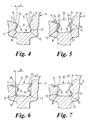
- the turbine disc 2 has a peripheral face 4 extending circumferentially about the disc axis.
- a root slot 6 to engage roots of turbine blades to be held in the turbine disc 2 is formed in the peripheral face 4.
- the root slot 6 extends circumferntially around the turbine disc 2 and as shown in Figure 4 has a cross-section shape which is adapted to receive and securely hold the turbine blade roots.
- Root slot 6 has a re-entrant or undercut shape at the deepest and widest part of its cross-section, having opposed concave recesses 8 and 10, which are spaced more widely apart than convex ribs 14, 20 immediately above.
- Each rib 14, 20 has an underside or flank 12.
- the root slot 6 includes in its side-walls cut-away portions 22, 24 comprising opposite arcuate bights in the convex ribs 16, 20. These bights together form a load slot 22, 24 for allowing entry and exit, or "loading” and “unloading", of turbine blade roots into the root slot 6 of the turbine disc 2 (see root 26 of turbine blade 30 in Figures 5 to 7).
- the root slot 6 also includes "shadow slots" 32, 34 and 36, 38. Each bight 32, 34, 36 or 38 of a said shadow slot extends, through the convex ribs 16, 20 towards the respective concave recess 8 or 10, similarly to the bights 22, 24 forming the load slot.
- the arcuate bights 22, 24 have substantially the same radius of curvature, and may have the same centre of curvature and thus be based on different arcs of the same circle which may have a diameter substantially equal to a maximum axial width of the root slot 6.
- each of the two opposite circumferential sides of the load slot 22,24 is a respective said shadow slot 32, 34 or 36, 38, as indicated, one shadow slot being formed by the oppositely disposed arcuate bights 32 and 34 respectively formed in the ribs 14 and 20, the other shadow slot being formed by the oppositely disposed arcuate bights 36 and 40 also in the respective ribs 14 and 20.
- the radius of curvature of each of the bights 32, 34, 36 or 38 is substantially the same.
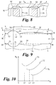
- Dotted line 42 or 44 each represents the locus of a respective side face 16 and 18 (see Figures 2 and 9) i.e. the position where the side faces would be were the bights 22, 24, 32, 34, 36 and 40 not present. Whilst either or each shadow slot 32,34 or 36,40 may be circumferentially spaced from the load slot 22, 24, in the arrangement shown in Figures 2 and 9 an end of each arcuate bight 32 and 36 coincides at 46 and 50 on the locus 42 with a respective opposite end of the arcuate bight 22 whilst an end of each arcuate bight 34 and 40 coincides at 52 and 54 on the locus 44 with a respective opposite end of the arcuate bight 24.
- each bight 32, 34, 36 or 38 is greater than that of the bights 22 and 24, for example, it may be at least twice that of the radius of curvature of the bights 22 and 24.
- the bights 32, 34, 36 and 38 extend through the ribs 14, 20 from the face 4 (see bight 32,34 in Figure 4).
- a maximum distance d of axial penetration into a rib 14 or 20 by a bight 32 or 36 from the respective locus 42 or 44 is shown in Figures 4 and 9 with respect to the bight 32.
- a maximum distance of axial penetration D into a rib 14 or 20 by a bight 22 or 24 from the respective locus 42 or 44 is shown in Figures 6 and 9.
- Dimension D can be plurality of times greater than dimension d.
- dimension D may be substantially at least twice dimension d
- dimension D may be substantially 2.0 to substantially 2.5 times greater than dimension d.
- the bights 32, 34, 36, 38 forming the shadow slots axially penetrate the ribs 14 and 20 to a significantly lesser extent than the bights 22, 24 forming the load slot.
- the radius of curvature of each bight 32, 34, 36, 38 forming the shadow slots may be at least substantially eight times greater than the radius of curvature of each bight 22, 24 forming the load slot.
- the width of the root slot 6 between the parallel side faces 16,18 may be substantially 5.351mm (0.211 inches);
- the radius of curvature of the bights forming the shadow slots 32,34 and 36, 38 may be substantially 8.13 times greater than the radius of curvature of the bights forming the load slot 22,24, and the ratio D/d has a numerical value of substantially 2.39.
- k t the peak hoop stress at centre line 56 of the load slot 22,24 the average hoop stress around the disc 2
- values of x are represented along the abscissa, where x is a circumferential distance measured from the centre line 56 ( Figure 9 along the face 4 and the position of the centre line 56 is represented as zero or the origin of the x - axis.
- graph 70 corresponds to a shadow slot bight 32,34 radius of curvature which is less than shadow slot bight radius of curvature to which graph 72 corresponds which in turn is less than the shadow slot bight radius of curvature to which graph 74 corresponds.
Landscapes
- Engineering & Computer Science (AREA)
- Mechanical Engineering (AREA)
- General Engineering & Computer Science (AREA)
- Turbine Rotor Nozzle Sealing (AREA)
Abstract
Description
Claims (18)
- A turbine disc rotatable about an axis, said turbine disc comprising a peripheral face extending circumferentially about the axis, the peripheral face having a root slot formed therein for engaging roots of turbine blades to be held in the turbine disc, the root slot having a longitudinal extent extending circumferentially around the turbine disc, a depth extending radially of the disc and a width defined between axially opposed side walls of the root slot, the root slot further having an undercut portion of its cross-section for accommodating the blade roots, at least one of the side-walls of the root slot above the undercut portion having cut-away portions includingwherein at least one of the bights constituting the shadow slots has a radius of curvature greater than the radius of curvature of the bight or bights constituting the load slot.(c) at least one arcuate bight defining a load slot for allowing entry and exit of the blade roots into the undercut portion of the root slot,(d) on circumferentially opposed sides of the load slot, a further at least one arcuate bight defining a shadow slot for reducing hoop stress concentrations in the perimeter of the turbine disc,
- A turbine disc as claimed in Claim 1, in which the load slot is constituted by a pair of opposite arcuate bights each in an opposed said side wall.
- A turbine disc as claimed in Claim 1, or Claim 2, in which each or a said shadow slot is constituted by a pair of opposite arcuate bights each in an opposed said side wall.
- A turbine disc as claimed in any one preceding Claim, in which at least one of the bights constituting the shadow slots has a radius of curvature at least substantially eight times greater than the radius of curvature of the bight or at least one of the bights constituting the load slot.
- A turbine disc as claimed in any one preceding claim, in which at least one of the bights constituting the shadow slots has a radius of curvature at least substantially eight times greater than the radius of curvature of the bight or at least one of the bights constituting the load shot.
- A turbine disc as claimed in any one preceding claim, in which the bights constituting a said shadow slot have substantially the same radius of curvature.
- A turbine disc as claimed in any one preceding claim, in which the side walls of the root slot comprise opposed, circumferentially extending first and second ribs having side faces facing across the root slot, wherein a first maximum distance which said bight or one of the bights constituting. the load slot extends axially of the disc into the respective first or second rib from a locus of the side face of the rib is greater than a second maximum distance which said bight or one of the bights constituting the shadow slots extends axially of the disc into the respective first or second rib from the locus of the side face of the rib.
- A turbine disc as claimed in Claim 7, in which said first maximum distance is at least a plurality of times greater than the second distance.
- A turbine disc as claimed in Claim 7, in which the first maximum distance is at least substantially twice the second maximum distance.
- A turbine disc as claimed in Claim 7, in which the first maximum distance is between substantially 2.0 and substantially 2.5 times greater than the second maximum distance.
- A turbine disc as claimed in any one preceding claim, in which with respect to at least one of the shadow slots an end of said bight or at least one of the bights constituting the load slot is circumferentially spaced from an adjacent end of said bight or at least one of the bights constituting the shadow slot.
- A turbine disc as claimed in any one of Claims 1 to 10, in which with respect to at least one of the shadow slots an end of said bight or at least one of the bights constituting the load slot substantially coincides with an end of said bight or at least one of the bights constituting the shadow slot.
- A turbine disc as claimed in Claim 7 and Claim 11 or in Claim 7 and Claim 12, in which said ends substantially lie on a said locus.
- A turbine disc as claimed in any one of Claims 1 to 11 or in Claim 13 when appended to Claim 11, in which at least one of said shadow slots is adjacent to the load slot.
- A turbine disc substantially as hereinbefore described with reference to Figures 2 to 10 of the accompanying drawings.
- A turbine wheel comprising a turbine disc as claimed in any one preceding claim, and turbine blades.
- A turbine engine or machine comprising a turbine wheel as claimed in Claim 16.
- A gas turbine engine comprising a turbine wheel as claimed in Claim 16.
Applications Claiming Priority (2)
| Application Number | Priority Date | Filing Date | Title |
|---|---|---|---|
| GB0016606 | 2000-07-07 | ||
| GB0016606A GB2364554B (en) | 2000-07-07 | 2000-07-07 | Turbine disc |
Publications (4)
| Publication Number | Publication Date |
|---|---|
| EP1170463A2 true EP1170463A2 (en) | 2002-01-09 |
| EP1170463A3 EP1170463A3 (en) | 2003-08-20 |
| EP1170463B1 EP1170463B1 (en) | 2005-10-19 |
| EP1170463B8 EP1170463B8 (en) | 2005-12-28 |
Family
ID=9895139
Family Applications (1)
| Application Number | Title | Priority Date | Filing Date |
|---|---|---|---|
| EP01305830A Expired - Lifetime EP1170463B8 (en) | 2000-07-07 | 2001-07-05 | Turbine disc |
Country Status (4)
| Country | Link |
|---|---|
| US (1) | US6471483B2 (en) |
| EP (1) | EP1170463B8 (en) |
| DE (1) | DE60114092T2 (en) |
| GB (1) | GB2364554B (en) |
Cited By (1)
| Publication number | Priority date | Publication date | Assignee | Title |
|---|---|---|---|---|
| EP2602435A3 (en) * | 2011-12-07 | 2017-04-05 | United Technologies Corporation | Turbomachine rotor and corresponding assembly method |
Families Citing this family (13)
| Publication number | Priority date | Publication date | Assignee | Title |
|---|---|---|---|---|
| DE10351092B4 (en) * | 2003-10-31 | 2013-11-21 | MTU Aero Engines AG | Turbomachine and bladed rotor for a compressor stage of a turbomachine |
| FR2873745B1 (en) * | 2004-07-28 | 2008-10-10 | Snecma Moteurs Sa | ROTOR DISC OF TURBOMACHINE |
| US9662721B2 (en) * | 2008-02-26 | 2017-05-30 | United Technologies Corporation | Method of generating a curved blade retention slot in a turbine disk |
| US8894370B2 (en) | 2008-04-04 | 2014-11-25 | General Electric Company | Turbine blade retention system and method |
| US8608447B2 (en) * | 2009-02-19 | 2013-12-17 | Rolls-Royce Corporation | Disk for turbine engine |
| US8403645B2 (en) * | 2009-09-16 | 2013-03-26 | United Technologies Corporation | Turbofan flow path trenches |
| US9127563B2 (en) * | 2011-04-05 | 2015-09-08 | General Electric Company | Locking device arrangement for a rotating bladed stage |
| US8689441B2 (en) | 2011-12-07 | 2014-04-08 | United Technologies Corporation | Method for machining a slot in a turbine engine rotor disk |
| EP2833940B1 (en) * | 2012-04-05 | 2018-08-22 | Mark L. Anderson | Intra rectal/vaginal applicator technology |
| US9341070B2 (en) * | 2012-05-30 | 2016-05-17 | United Technologies Corporation | Shield slot on side of load slot in gas turbine engine rotor |
| US20140182293A1 (en) * | 2012-12-31 | 2014-07-03 | United Technologies Corporation | Compressor Rotor for Gas Turbine Engine With Deep Blade Groove |
| FR3064667B1 (en) * | 2017-03-31 | 2020-05-15 | Safran Aircraft Engines | DEVICE FOR COOLING A TURBOMACHINE ROTOR |
| JP6800813B2 (en) | 2017-06-21 | 2020-12-16 | 三菱重工航空エンジン株式会社 | Stress reduction structure, gas turbine casing and gas turbine |
Family Cites Families (9)
| Publication number | Priority date | Publication date | Assignee | Title |
|---|---|---|---|---|
| GB916001A (en) * | 1961-02-09 | 1963-01-16 | Prvni Brnenska Strojirna | Improvements in or relating to rotors for turbines and compressors |
| GB980337A (en) * | 1962-05-08 | 1965-01-13 | Power Jets Res & Dev Ltd | Improvements in or relating to a rotor for a compressor turbine or like bladed fluidflow machine |
| US3216700A (en) * | 1963-10-24 | 1965-11-09 | Gen Electric | Rotor blade locking means |
| US3742706A (en) * | 1971-12-20 | 1973-07-03 | Gen Electric | Dual flow cooled turbine arrangement for gas turbine engines |
| US3902824A (en) * | 1974-07-29 | 1975-09-02 | Gen Motors Corp | Blade lock |
| US4482297A (en) * | 1981-11-16 | 1984-11-13 | Terry Corporation | Bladed rotor assembly |
| US5232346A (en) * | 1992-08-11 | 1993-08-03 | General Electric Company | Rotor assembly and platform spacer therefor |
| FR2723397B1 (en) * | 1994-08-03 | 1996-09-13 | Snecma | TURBOMACHINE COMPRESSOR DISC WITH AN ASYMMETRIC CIRCULAR THROAT |
| US5846054A (en) * | 1994-10-06 | 1998-12-08 | General Electric Company | Laser shock peened dovetails for disks and blades |
-
2000
- 2000-07-07 GB GB0016606A patent/GB2364554B/en not_active Expired - Fee Related
-
2001
- 2001-07-05 EP EP01305830A patent/EP1170463B8/en not_active Expired - Lifetime
- 2001-07-05 DE DE60114092T patent/DE60114092T2/en not_active Expired - Lifetime
- 2001-07-05 US US09/899,557 patent/US6471483B2/en not_active Expired - Fee Related
Cited By (3)
| Publication number | Priority date | Publication date | Assignee | Title |
|---|---|---|---|---|
| EP2602435A3 (en) * | 2011-12-07 | 2017-04-05 | United Technologies Corporation | Turbomachine rotor and corresponding assembly method |
| US10107114B2 (en) | 2011-12-07 | 2018-10-23 | United Technologies Corporation | Rotor with relief features and one-sided load slots |
| US10704401B2 (en) | 2011-12-07 | 2020-07-07 | Raytheon Technologies Corporation | Rotor with relief features and one-sided load slots |
Also Published As
| Publication number | Publication date |
|---|---|
| GB2364554B (en) | 2004-04-07 |
| US6471483B2 (en) | 2002-10-29 |
| DE60114092D1 (en) | 2005-11-24 |
| EP1170463B1 (en) | 2005-10-19 |
| DE60114092T2 (en) | 2006-04-20 |
| US20020015642A1 (en) | 2002-02-07 |
| GB0016606D0 (en) | 2000-08-23 |
| GB2364554A (en) | 2002-01-30 |
| EP1170463A3 (en) | 2003-08-20 |
| EP1170463B8 (en) | 2005-12-28 |
Similar Documents
| Publication | Publication Date | Title |
|---|---|---|
| EP1170463B1 (en) | Turbine disc | |
| EP1219782B1 (en) | Bladed rotor assembly | |
| US5211540A (en) | Shrouded aerofoils | |
| EP0335481B1 (en) | Wall having cooling passage | |
| US8777558B2 (en) | Casing for a moving-blade wheel of turbomachine | |
| US5509784A (en) | Turbine bucket and wheel assembly with integral bucket shroud | |
| CA1067004A (en) | Pneumatic tire for vehicles having improved handling and road gripping | |
| US5310318A (en) | Asymmetric axial dovetail and rotor disk | |
| US5373882A (en) | Pneumatic tires | |
| EP0602989A1 (en) | Pneumatic tyre | |
| EP0173783B1 (en) | Pneumatic tires | |
| EP0274978B1 (en) | Multiple lug blade to disk attachment | |
| US5891276A (en) | Pneumatic tire for heavy duty including narrow block | |
| US20060263213A1 (en) | Steep angle turbine cover buckets having relief grooves | |
| US10807417B2 (en) | Heavy vehicle tire tread with improvement to running noise | |
| US5271718A (en) | Lightweight platform blade | |
| JPH06270608A (en) | Pneumatic tire | |
| EP0427543A2 (en) | Pneumatic tires | |
| US4482297A (en) | Bladed rotor assembly | |
| EP1058772B1 (en) | Turbine blade attachment stress reduction rings | |
| JPH0577608A (en) | Pneumatic tire for heavy load | |
| US1890581A (en) | Blades for turbine rotors | |
| US4468211A (en) | Toothed belt manufacture | |
| US5528952A (en) | Webbed bevel gear | |
| GB2117086A (en) | Piston rings |
Legal Events
| Date | Code | Title | Description |
|---|---|---|---|
| PUAI | Public reference made under article 153(3) epc to a published international application that has entered the european phase |
Free format text: ORIGINAL CODE: 0009012 |
|
| AK | Designated contracting states |
Kind code of ref document: A2 Designated state(s): AT BE CH CY DE DK ES FI FR GB GR IE IT LI LU MC NL PT SE TR |
|
| AX | Request for extension of the european patent |
Free format text: AL;LT;LV;MK;RO;SI |
|
| PUAL | Search report despatched |
Free format text: ORIGINAL CODE: 0009013 |
|
| AK | Designated contracting states |
Designated state(s): AT BE CH CY DE DK ES FI FR GB GR IE IT LI LU MC NL PT SE TR |
|
| AX | Request for extension of the european patent |
Extension state: AL LT LV MK RO SI |
|
| 17P | Request for examination filed |
Effective date: 20030809 |
|
| AKX | Designation fees paid |
Designated state(s): DE ES FR GB IT |
|
| 17Q | First examination report despatched |
Effective date: 20040429 |
|
| GRAP | Despatch of communication of intention to grant a patent |
Free format text: ORIGINAL CODE: EPIDOSNIGR1 |
|
| GRAS | Grant fee paid |
Free format text: ORIGINAL CODE: EPIDOSNIGR3 |
|
| GRAA | (expected) grant |
Free format text: ORIGINAL CODE: 0009210 |
|
| AK | Designated contracting states |
Kind code of ref document: B1 Designated state(s): DE ES FR GB IT |
|
| REG | Reference to a national code |
Ref country code: GB Ref legal event code: FG4D |
|
| REF | Corresponds to: |
Ref document number: 60114092 Country of ref document: DE Date of ref document: 20051124 Kind code of ref document: P |
|
| RAP2 | Party data changed (patent owner data changed or rights of a patent transferred) |
Owner name: ALSTOM TECHNOLOGY LTD |
|
| ET | Fr: translation filed | ||
| REG | Reference to a national code |
Ref country code: FR Ref legal event code: TP |
|
| PLBE | No opposition filed within time limit |
Free format text: ORIGINAL CODE: 0009261 |
|
| STAA | Information on the status of an ep patent application or granted ep patent |
Free format text: STATUS: NO OPPOSITION FILED WITHIN TIME LIMIT |
|
| 26N | No opposition filed |
Effective date: 20060720 |
|
| PGFP | Annual fee paid to national office [announced via postgrant information from national office to epo] |
Ref country code: FR Payment date: 20110727 Year of fee payment: 11 |
|
| PGFP | Annual fee paid to national office [announced via postgrant information from national office to epo] |
Ref country code: DE Payment date: 20110729 Year of fee payment: 11 |
|
| PGFP | Annual fee paid to national office [announced via postgrant information from national office to epo] |
Ref country code: IT Payment date: 20110719 Year of fee payment: 11 |
|
| REG | Reference to a national code |
Ref country code: FR Ref legal event code: ST Effective date: 20130329 |
|
| PG25 | Lapsed in a contracting state [announced via postgrant information from national office to epo] |
Ref country code: FR Free format text: LAPSE BECAUSE OF NON-PAYMENT OF DUE FEES Effective date: 20120731 Ref country code: DE Free format text: LAPSE BECAUSE OF NON-PAYMENT OF DUE FEES Effective date: 20130201 |
|
| REG | Reference to a national code |
Ref country code: DE Ref legal event code: R119 Ref document number: 60114092 Country of ref document: DE Effective date: 20130201 |
|
| PG25 | Lapsed in a contracting state [announced via postgrant information from national office to epo] |
Ref country code: IT Free format text: LAPSE BECAUSE OF NON-PAYMENT OF DUE FEES Effective date: 20120705 |