EP1170240A2 - Transfer roll - Google Patents
Transfer roll Download PDFInfo
- Publication number
- EP1170240A2 EP1170240A2 EP01113445A EP01113445A EP1170240A2 EP 1170240 A2 EP1170240 A2 EP 1170240A2 EP 01113445 A EP01113445 A EP 01113445A EP 01113445 A EP01113445 A EP 01113445A EP 1170240 A2 EP1170240 A2 EP 1170240A2
- Authority
- EP
- European Patent Office
- Prior art keywords
- transfer roll
- cylindrical
- skin
- roll according
- strip
- Prior art date
- Legal status (The legal status is an assumption and is not a legal conclusion. Google has not performed a legal analysis and makes no representation as to the accuracy of the status listed.)
- Granted
Links
Images

Classifications
-
- B—PERFORMING OPERATIONS; TRANSPORTING
- B65—CONVEYING; PACKING; STORING; HANDLING THIN OR FILAMENTARY MATERIAL
- B65G—TRANSPORT OR STORAGE DEVICES, e.g. CONVEYORS FOR LOADING OR TIPPING, SHOP CONVEYOR SYSTEMS OR PNEUMATIC TUBE CONVEYORS
- B65G39/00—Rollers, e.g. drive rollers, or arrangements thereof incorporated in roller-ways or other types of mechanical conveyors
- B65G39/02—Adaptations of individual rollers and supports therefor
- B65G39/04—Adaptations of individual rollers and supports therefor the rollers comprising a number of roller forming elements mounted on a single axle
-
- B—PERFORMING OPERATIONS; TRANSPORTING
- B21—MECHANICAL METAL-WORKING WITHOUT ESSENTIALLY REMOVING MATERIAL; PUNCHING METAL
- B21B—ROLLING OF METAL
- B21B38/00—Methods or devices for measuring, detecting or monitoring specially adapted for metal-rolling mills, e.g. position detection, inspection of the product
- B21B38/02—Methods or devices for measuring, detecting or monitoring specially adapted for metal-rolling mills, e.g. position detection, inspection of the product for measuring flatness or profile of strips
-
- B—PERFORMING OPERATIONS; TRANSPORTING
- B21—MECHANICAL METAL-WORKING WITHOUT ESSENTIALLY REMOVING MATERIAL; PUNCHING METAL
- B21B—ROLLING OF METAL
- B21B39/00—Arrangements for moving, supporting, or positioning work, or controlling its movement, combined with or arranged in, or specially adapted for use in connection with, metal-rolling mills
- B21B39/008—Rollers for roller conveyors
-
- B—PERFORMING OPERATIONS; TRANSPORTING
- B65—CONVEYING; PACKING; STORING; HANDLING THIN OR FILAMENTARY MATERIAL
- B65H—HANDLING THIN OR FILAMENTARY MATERIAL, e.g. SHEETS, WEBS, CABLES
- B65H23/00—Registering, tensioning, smoothing or guiding webs
- B65H23/04—Registering, tensioning, smoothing or guiding webs longitudinally
- B65H23/044—Sensing web tension
-
- B—PERFORMING OPERATIONS; TRANSPORTING
- B65—CONVEYING; PACKING; STORING; HANDLING THIN OR FILAMENTARY MATERIAL
- B65H—HANDLING THIN OR FILAMENTARY MATERIAL, e.g. SHEETS, WEBS, CABLES
- B65H27/00—Special constructions, e.g. surface features, of feed or guide rollers for webs
-
- F—MECHANICAL ENGINEERING; LIGHTING; HEATING; WEAPONS; BLASTING
- F16—ENGINEERING ELEMENTS AND UNITS; GENERAL MEASURES FOR PRODUCING AND MAINTAINING EFFECTIVE FUNCTIONING OF MACHINES OR INSTALLATIONS; THERMAL INSULATION IN GENERAL
- F16C—SHAFTS; FLEXIBLE SHAFTS; ELEMENTS OR CRANKSHAFT MECHANISMS; ROTARY BODIES OTHER THAN GEARING ELEMENTS; BEARINGS
- F16C13/00—Rolls, drums, discs, or the like; Bearings or mountings therefor
-
- B—PERFORMING OPERATIONS; TRANSPORTING
- B65—CONVEYING; PACKING; STORING; HANDLING THIN OR FILAMENTARY MATERIAL
- B65H—HANDLING THIN OR FILAMENTARY MATERIAL, e.g. SHEETS, WEBS, CABLES
- B65H2402/00—Constructional details of the handling apparatus
- B65H2402/60—Coupling, adapter or locking means
Definitions
- the invention is a device used in continuous and semi-continuous processes for the production of substantially flat material in a sheet, web or strip of materials such as paper or metals including copper, steel or aluminium. More particularly the invention is a transfer roll for use industrial processes such as in a paper machine or a rolling mill where a material is produced or processed as a strip.
- strip material In the production and processing of strip and sheet materials it is a basic requirement that a strip material is produced to a specification which typically includes at least a predetermined thickness and predetermined material properties. To achieve such predetermined requirements any mechanical forces applied to the strip during processing must be accurately controlled.
- a transfer roll that conveys strip material from one part of a process to another must convey the material while exerting a controlled tension or pressure that is accurately controlled and evenly distributed over the width of the roll.
- a roll described in US patent US 3,481,194 issued in 1969 is designed as a measuring roll to measure flatness in a metal strip passing over the roll. Flatness is indirectly measured by the measuring roll with the help of a number of force sensors arranged inside the roll and against the inside of the outer cylindrical surface.
- the roll is notionally divided into a number of parallel zones across the width of the measuring roll and a force sensor measures a force applied by the roll to the strip in each zone.
- process control techniques may be used to correct or optimise those forces to regulate properties of the strip such as, for example, tensile strength, flatness or other dimensional qualities.
- demands for increased accuracy over time means that it is difficult to measure certain forces in any one zone accurately. This is because of a tendency for a force applied in a zone of the roll to be shared with or transferred to an adjacent zone.
- Transfer of force in an unintended or uncontrolled way is sometimes described as crosstalk. It is used in this description to describe uncontrolled transfer of mechanical forces between mechanically connected parts of a transfer roll.
- US 4,366,720 discloses a method of constructing a deflector roll, or a measuring roll.
- the roll is constructed using a series of disk-shaped sections of a cylinder, some of which are equipped with force measuring sensors.
- a difficulty arises with cylindrical rolls comprising such disk-shaped sections.
- contaminants such as dirt, grease, particulate material or oxides to become trapped between neighbouring disk sections during normal use. This can give rise to a partial and unregulated transfer of force, crosstalk, between the disks, making it difficult to ensure accuracy of force distribution across the roll and of force measurement in areas distributed across the roll.
- Another object of the invention is to provide a method for welding together cylindrical elements to provide a transfer roll in which the cylindrical elements are mechanically connected to each other to a known and predetermined extent.
- a yet another object of the invention is to provide a transfer roll in which the cylinder or cylindrical elements making up the cylinder are in a pre-stressed condition.
- a further object of the invention is to provide a means for measuring a property of a strip material which measured value maybe used in a monitoring, control or regulation function for the same strip material in the same or another process.
- the invention may be summarily described as a transfer roll that carries a flat or strip material over from one device to another in a process.
- the present invention is a transfer roll in which at least the inside surface of the cylindrical skin of the roll is wholly or partly separated into two or more cylindrical elements.
- the degree of dependency due to crosstalk is known based on the predetermined mechanical stiffness and may be compensated for by calculation. This provides a consequent and decisive improvement in accuracy compared to existing transfer rolls. Consequently an error in a material property of the strip material passing over the transfer roll may be detected with greater accuracy than before.
- error measurements measured with a greater accuracy than previously may subsequently used to reduce or correct such errors in the present process or another process for the same material.
- the main advantage of the invention is that a strip of flat material may be processed or produced to a required property specification such as thickness or flatness with less error, and consequently less downgrading of product, scrap and waste.
- a required property specification such as thickness or flatness
- Such a significant reduction in errors and scrap will produce a large environmental benefit in terms of reduced use of materials and energy in the industrial processes where the transfer roll is used.
- the economic benefit of improved accuracy and reducing waste of materials and energy in continuous and other processes producing vast quantities of, for example, paper, board, foils, metals and plastic or synthetic materials is also great.
- a method for providing a welded joint as a means for providing a region of predetermined and reduced stiffness between any two cylindrical elements of the transfer roll is described.
- An advantage of the method disclosed according to a best use of the present invention is that the design of the joint also acts to prevent molten material from the welded joint from entering the interior of the transfer roll.
- Another advantage of this method is that any small variation in depth of weld is accommodated by an advantageous allowance in thickness of an un-fused part of the element cross section.
- a further advantage of the welded joint is that the cylindrical elements may conveniently and separately be pre-stressed before they are joined together. Pre-stressing the cylindrical skin provides for increased accuracy of measurement of force applied by the roller to a strip.
- the welded joint once made may also be made perfectly smooth on the outside surface of the transfer roll using conventional manufacturing techniques for producing metal covered rolls.
- the outer surface is made perfectly flat and level to the specifications normally required so as not to mark or mar the surface of a web of material or a rolled strip.
- Such a welded joint may also be produced to so that it is seamless and complete, preventing the build up or penetration of contaminants of any sort.
- a still further advantage of the invention is that the accuracy of measurement across the roll is greatly improved relative to the prior art, and so the transfer roll may be used in new applications and branches of industry where the previous limitations of accuracy made such transfer rolls and measuring rolls problematic.
- transfer roll may be easily and economically retrofitted to existing processes to improve accuracy and thus reduce costs.
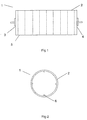
- Figure 1 shows schematically an axial section of a transfer roll arranged as a flatness measuring roll according to the known art.
- Figure 2 shows schematically a cross section of the same transfer roll according to the known art.
- Figure 3 shows a simplified cross section diagram of a transfer roll according to an embodiment of the present invention.
- Figure 4 shows a schematic diagram of a cross section of a joint between two cylindrical elements of a transfer roll according to an embodiment of the present invention.
- a roll equipped with measuring means arranged to measure flatness of a strip of rolled metal according to a method and device from the Prior Art is shown in Figure 1 and Figure 2.
- Figure 1 shows a cross section of a transfer roll 1 along the long axis of the cylinder with a cylindrical outer shell 2 arranged between two ends 3, 4.
- the cylinder surface is notionally divided up into a series of zones 5 for measurement.
- Figure 2 shows an axial cross section of the same roll arranged with sensors inside the cylinder including sensor 6.
- One or more sensors are arranged inside the cylinder in contact with the cylindrical skin of the roll at one or more points around the periphery in one or more zones. As the roll rotates, a force exerted by the cylindrical skin against a strip of material passing over the roll is measured in each zone by each of the one or more sensors.
- FIG. 3 shows a transfer roll according to an embodiment of the present invention.
- a cylindrical skin 2 is shown.
- the cylindrical skin contains cylindrical elements such as 8 and recesses 7 in the inside surface of the cylindrical skin.
- the cylindrical skin 2 is thus thinner between the cylindrical elements where the recesses 7 are arranged.
- FIG. 4 shows a preferred method to provide an embodiment of the present invention.
- a schematic section through a joint 9 between two cylindrical elements 8a, 8b is illustrated. Cylindrical elements 8a, 8b are joined by a predetermined thickness of material 11. The predetermined thickness 11 may be likened to a step of material which is matched up with a co-operating and underlying step at the end of the other cylindrical element 8b.
- the underlying step of 8b is defined by a depth equal to dimensions 14a plus 14b and a length in the axial direction equal to dimension 12.
- a welded joint 9 is shown taking up a depth equivalent to the predetermined thickness 11.
- a heat effected zone for that weld depth is illustrated and indicated as 14a.
- a dotted line 14b shows where the depth of weld may vary only up to a predetermined additional depth 10.
- the recess 7 is shown in the cross section.
- a plurality of recesses 7 divide up the cylindrical skin of the transfer roll into a number of cylindrical elements 8.
- Each element is joined at the cylindrical periphery by a predetermined thickness of material 11 which is selected so as to give a predetermined mechanical rigidity.
- the use of a means to reduce stiffness between the cylindrical elements makes the cylindrical elements mechanically dependent on each other to a known, constant and predetermined extent, thus limiting crosstalk between the sections, within the operating limits of the transfer roll.
- a force applied at a point on the surface of one cylindrical element of the transfer roll has a limited but predictable and calculable force on any other cylindrical element.
- the force measured at the point of the surface may be compensated accurately for a known and limited degree of crosstalk from a force acting on another cylindrical element.
- the joint is further designed in cross section as a Z-shape.
- the Z-shape of the weld allows for a variation in the depth of the weld, from 11 to a depth of 10 without affecting the effective predetermined thickness of the joint 11, and thus without affecting the predetermined stiffness.
- the Z-shape of the weld also prevents any molten material from flowing into the inside of the cylinder.
- An additional advantageous aspect of this method is that one or more cylinder elements may be treated before joining them together to improve the physical properties of the element.
- one or more ring elements may advantageously be pre-stressed before joining in order to improve the mechanical behaviour of the element for operating or measuring purposes. This is beneficial in arranging the cylindrical skin to apply a desired pre-stressing force to force sensors mounted inside the roll.
- one or more sensors are placed inside the cylindrical skin in a similar way to the prior art. Sensors may be placed in one or more cylindrical elements. Magnetoelastic sensors of the Pressductor type are used to give an accurate and reliable measurement of a mechanical force applied to the skin of the transfer roll.
- a magnetoelastic sensor of the Pressductor type is based on the fact that the magnetic permeability of a magnetic material changes under mechanical stress.
- This type of sensor has a primary and a secondary winding each wound through the same two holes in a sensor material comprising a stack of magnetostrictive metal lamella.
- the primary winding is provided with alternating current for magnetisation of the material.
- the secondary winding measures voltages that arise due to mechanical load imposed on the magnetostrictive material of the sensor.
- Another type of magnetoelastic sensor may be used to provide greater accuracy, such as in the manufacturing of metal foils, which sensor comprises regions of sensor material with a primary and a secondary winding separately wound through four holes in the sensor material such that the two windings cross at right angles.
- a plurality of measurements from sensors in the transfer roll provides a measurement of distribution of the measured force over the skin of the cylinder, and thus on or in the strip material running over the transfer roll. Such measurements are used to calculate tension in the material being transferred, tension on the transfer roll. These measurements in turn may be used to calculate dimensional properties such as flatness or thickness or other properties of a strip material.
- a control unit is used to collect the measurements made by the sensors.
- a control unit is typically equipped with storage means and calculating means. It is preferably arranged connected to one or more databases for the storage of measured values and calculated values of one or more properties of the flat or rolled strip material.
- the transfer roll comprises an active component of a measurement system for supervising and/or regulating a property of the strip material.
- a different method is used to provide a roll with a cylindrical skin that is internally divided into cylindrical elements.
- the method is to make a cylindrical cut on the inside of the cylindrical skin to a predetermined depth using a suitable cutting device or tool.
- a recess of the correct depth may be provided leaving the cylindrical elements connected together by a region of material of the cylindrical skin that has been reduced to a predetermined thickness.
- the recess may have any cross section, for example or hemispherical.
- the material be removed from the cylindrical skin by cutting, melting, spark erosion or other suitable means to form a substantially complete cylindrical recess between two cylindrical elements.
- the means for reduced stiffness is a localized region in which material properties are different from the surrounding material. This is accomplished by changing the material microstructure so that the rigidity is reduced in a localized region. This may be accomplished for example by localized heat treatment.
- the preferred sensor for use in the invention is, as stated above, a magnetoelastic sensor that depends on a magneostrictive property of a magnetic material to produce a signal in a measurement coil in proportion to a mechanical load applied to that material.
- a magnetoelastic sensor that depends on a magneostrictive property of a magnetic material to produce a signal in a measurement coil in proportion to a mechanical load applied to that material.
- sensors based on other measurement techniques such as, for example, strain gauges, piezo electic materials.
Landscapes
- Engineering & Computer Science (AREA)
- Mechanical Engineering (AREA)
- General Engineering & Computer Science (AREA)
- Registering, Tensioning, Guiding Webs, And Rollers Therefor (AREA)
- Rolls And Other Rotary Bodies (AREA)
- Force Measurement Appropriate To Specific Purposes (AREA)
- Butt Welding And Welding Of Specific Article (AREA)
- Controlling Rewinding, Feeding, Winding, Or Abnormalities Of Webs (AREA)
- Feeding And Guiding Record Carriers (AREA)
- Vending Machines For Individual Products (AREA)
- Sheets, Magazines, And Separation Thereof (AREA)
Abstract
Description
Claims (23)
- A transfer roll (1) for conveying a strip of substantially flat material, which transfer roll includes an outer cylindrical skin (2), characterised in that said cylindrical skin of said transfer roll comprises at least two cylindrical elements (8a, 8b) between which is arranged a means (7) for providing a region of cylindrical skin of predetermined and reduced mechanical stiffness relative to the stiffness of the remainder of the cylindrical skin.
- A transfer roll according to claim 1, characterised in that said means (7) is a region of the cylindrical skin including a reduction in cross section thickness.
- A transfer roll according to claim 2, characterised in that said means (7) comprises a joint (9) and the cylindrical elements are joined together such that the cross section of the resulting cylinder is reduced in thickness at the joint relative to the cross section of the remainder of the cylindrical skin.
- A transfer roll according to claim 3, characterised in that said joint (9) is a welded joint.
- A transfer roll according to claim 4, characterised in that the welded joint (9) between the two cylindrical elements is formed between a step (11) of reduced thickness in the cylindrical skin material of the substantially circular end of one cylindrical element (8a) and an underlying co-operating step in a circular end of the other cylindrical element (8b).
- A transfer roll according to claim 1, characterised in that one or more cylindrical elements of the transfer roll is in a pre-stressed condition.
- A transfer roll according to claim 1, characterised in that said means (7) for reducing the mechanical stiffness of the cylindrical skin comprises at least one recess made in the interior surface of the cylindrical skin (2) of the transfer roll (1).
- A transfer roll according to claim 1, characterised in that the means (7) for reducing the mechanical stiffness of the cylindrical skin comprises at least one cylindrical region in the material of the cylindrical skin (2) of the transfer roll (1) in which the microstructure of the material has been altered.
- A transfer roll according to claim 1, characterised in that one or more sensors capable of measuring a mechanical force are arranged adjacent the inside surface of the cylindrical skin in one or more of each cylindrical element comprising said transfer roll.
- A transfer roll according to claim 9, characterised in that the one or more force sensors is a magnetoelastic sensor.
- A transfer roll according to claim 9, characterised in that the one or more force sensors comprise a strain gauge.
- A transfer roll according to claim 9, characterised in that the one or more force sensors comprise a piezo-electric sensor.
- A transfer roll according to any of claims 1-12, characterised in that the outer cylindrical surface of the transfer roll is flat and level.
- The use of a transfer roll according to any of claims 1-13 for measuring a property of a strip (1) of flat or rolled material.
- The use of a transfer roll according to any of claims 1-13 for measuring a force exerted by said transfer roll against a strip (1).
- The use of a transfer roll according to any of claims 1-13 for measuring the flatness of a strip (1).
- A method to provide a transfer roll (1) wherein at least two or more cylindrical elements (8a, 8b) are joined together, characterised by the step of welding together said two or more cylindrical elements producing a welded joint (9) between the substantially circular ends of said two or more cylindrical elements.
- A method according to claim 17, characterised in that said two or more cylindrical elements are joined by a partial thickness (11) only of the cross section of the cylindrical skin adjacent to the joint.
- A method according to claim 17, characterised by the additional step of pre-stressing a cylindrical element before joining it to one or more other cylindrical elements.
- A method to provide a transfer roll according to claim 18, characterised by making smooth the outer surface of the cylinder such the cylindrical skin including the joints between cylindrical elements is flat and level on the outside of the transfer roll.
- A method to provide a transfer roll according to claim 17, characterised by removing material from the interior surface of the cylindrical skin between two cylindrical elements so forming one or more recesses in the cylindrical skin (2) of the transfer roll.
- A system for measuring a characteristic of a strip of flat or rolled material, comprising a transfer roll (1) arranged with sensors for measurement of a force placed inside said transfer roll, and a control unit for processing measurement values from said sensors, characterised in that the transfer roll comprises a cylindrical skin (2) comprising a plurality of cylindrical elements (8a, 8b) and a means (7) for providing a region of cylindrical skin of predetermined and reduced mechanical stiffness together such that the stiffness of the joint (9) is known and less than the stiffness of the surrounding material of the cylindrical element.
- The use of a system according to claim 22 for measuring a property of a strip (1) of flat or rolled material.
Applications Claiming Priority (2)
| Application Number | Priority Date | Filing Date | Title |
|---|---|---|---|
| SE0002558A SE517543C2 (en) | 2000-07-07 | 2000-07-07 | Transport roller with sensors and cylinders composed of means with reduced cross section and manufacture and system for measurement with this |
| SE0002558 | 2000-07-07 |
Publications (3)
| Publication Number | Publication Date |
|---|---|
| EP1170240A2 true EP1170240A2 (en) | 2002-01-09 |
| EP1170240A3 EP1170240A3 (en) | 2004-06-16 |
| EP1170240B1 EP1170240B1 (en) | 2007-01-24 |
Family
ID=20280398
Family Applications (1)
| Application Number | Title | Priority Date | Filing Date |
|---|---|---|---|
| EP01113445A Expired - Lifetime EP1170240B1 (en) | 2000-07-07 | 2001-06-02 | Transfer roll |
Country Status (7)
| Country | Link |
|---|---|
| US (1) | US6508115B2 (en) |
| EP (1) | EP1170240B1 (en) |
| JP (1) | JP4953524B2 (en) |
| AT (1) | ATE352506T1 (en) |
| DE (1) | DE60126194T2 (en) |
| ES (1) | ES2280285T3 (en) |
| SE (1) | SE517543C2 (en) |
Families Citing this family (2)
| Publication number | Priority date | Publication date | Assignee | Title |
|---|---|---|---|---|
| CN102707497B (en) * | 2011-11-15 | 2014-08-06 | 京东方科技集团股份有限公司 | Friction cloth checking machine and friction cloth checking method |
| US11975924B2 (en) * | 2019-08-09 | 2024-05-07 | Superior Industries, Inc. | Conveyor pulley apparatus, systems, and methods |
Family Cites Families (13)
| Publication number | Priority date | Publication date | Assignee | Title |
|---|---|---|---|---|
| DE1573407B1 (en) * | 1965-10-05 | 1970-09-03 | Asea Ab | Arrangement in strip rolling mills to measure the distribution of the strip tension over the strip width |
| FR2314471A1 (en) * | 1975-06-13 | 1977-01-07 | Secim | DEFLECTOR ROLLER FOR MEASURING AND CHECKING THE FLATNESS OF A TENSIONED SHEET IN MOVEMENT |
| JPS5588918A (en) * | 1978-12-27 | 1980-07-05 | Kuroki Kogyosho:Kk | Carrier roll for hot metallic billet |
| DE2924315A1 (en) * | 1979-06-15 | 1980-12-18 | Betr Forsch Inst Angew Forsch | DEVICE FOR MEASURING THE VOLTAGE DISTRIBUTION OVER THE WIDTH OF BENDING TAPES |
| FR2468878A1 (en) * | 1979-10-26 | 1981-05-08 | Secim | DEVICE FOR DETECTING PLANAR FAULTS OF A TENDERED BAND IN DISPLACEMENT |
| DE2944723A1 (en) * | 1979-11-06 | 1981-05-14 | Betriebsforschungsinstitut VDEh - Institut für angewandte Forschung GmbH, 4000 Düsseldorf | DEVICE FOR MEASURING THE VOLTAGE DISTRIBUTION OVER THE WIDTH OF BENDING TAPES |
| US4428244A (en) * | 1981-11-20 | 1984-01-31 | Sumitomo Light Metal Industries, Ltd. | Apparatus for measuring internal stress of strip during rolling process |
| JPS5985930A (en) * | 1982-11-10 | 1984-05-18 | Hitachi Ltd | shape detection device |
| JPS6084152A (en) * | 1983-06-02 | 1985-05-13 | 株式会社 サタケ | Pressure controller of grain refiner |
| SE461298B (en) * | 1988-06-02 | 1990-01-29 | Asea Brown Boveri | PLANET METERS FOR ROLLED BANDS |
| FR2684441A1 (en) * | 1991-12-02 | 1993-06-04 | Siderurgie Fse Inst Rech | FLAT MEASUREMENT ROLLER OF A CONTINUOUSLY MADE STRIP. |
| JPH09145503A (en) * | 1995-11-27 | 1997-06-06 | Kawasaki Steel Corp | Strip shape detector |
| FI105804B (en) * | 1997-01-30 | 2000-10-13 | Valmet Corp | Removal roller, width stretch roller or equivalent for web material |
-
2000
- 2000-07-07 SE SE0002558A patent/SE517543C2/en not_active IP Right Cessation
-
2001
- 2001-06-02 ES ES01113445T patent/ES2280285T3/en not_active Expired - Lifetime
- 2001-06-02 AT AT01113445T patent/ATE352506T1/en active
- 2001-06-02 DE DE60126194T patent/DE60126194T2/en not_active Expired - Lifetime
- 2001-06-02 EP EP01113445A patent/EP1170240B1/en not_active Expired - Lifetime
- 2001-06-15 US US09/880,785 patent/US6508115B2/en not_active Expired - Lifetime
- 2001-07-09 JP JP2001208614A patent/JP4953524B2/en not_active Expired - Fee Related
Also Published As
| Publication number | Publication date |
|---|---|
| ATE352506T1 (en) | 2007-02-15 |
| SE517543C2 (en) | 2002-06-18 |
| JP4953524B2 (en) | 2012-06-13 |
| SE0002558L (en) | 2002-01-08 |
| DE60126194D1 (en) | 2007-03-15 |
| JP2002122131A (en) | 2002-04-26 |
| DE60126194T2 (en) | 2007-12-13 |
| US6508115B2 (en) | 2003-01-21 |
| SE0002558D0 (en) | 2000-07-07 |
| ES2280285T3 (en) | 2007-09-16 |
| US20020005067A1 (en) | 2002-01-17 |
| EP1170240A3 (en) | 2004-06-16 |
| EP1170240B1 (en) | 2007-01-24 |
Similar Documents
| Publication | Publication Date | Title |
|---|---|---|
| AT506925B1 (en) | LOAD MEASUREMENT DEVICE, DEVICE MANUFACTURING METHOD AND CONTROL PROCESS USING THE DEVICE | |
| DE10224938B4 (en) | Method and device for flatness measurement of bands | |
| EP0301008B1 (en) | Shapemeter | |
| JP3580303B2 (en) | Endless metal belt manufacturing method and manufacturing apparatus | |
| EP0647484A1 (en) | Method of rolling and cutting endless hot-rolled steel strip | |
| US6508115B2 (en) | Transfer roll | |
| KR100295519B1 (en) | Roll and roll production method for metal sheet continuous casting machine suitable for continuous casting machine | |
| JP4055850B2 (en) | Flow forming method and apparatus | |
| JP4121050B2 (en) | Method and apparatus for manufacturing metal strip with embossed pattern | |
| EP2087949B1 (en) | Mandrel mill and process for manufacturing seamless pipe | |
| JP2987744B2 (en) | Shape sensor roll | |
| JP3584709B2 (en) | Rolling apparatus and furnace outer wall construction method | |
| JP2826167B2 (en) | Method and apparatus for correcting plate shape asymmetry | |
| JP2978056B2 (en) | Prediction method of contact wear between rolls of rolling mill | |
| JP7098626B2 (en) | Methods and equipment for rolling metal strips | |
| JP3045070B2 (en) | Manufacturing method of tapered plate | |
| JPH02280909A (en) | Rolling roll and rolling method using the same roll | |
| JPS61193714A (en) | Wedge controlling method in plate rolling | |
| JPH0618651B2 (en) | Width direction plate thickness difference control method and control device in the longitudinal direction of a thin steel plate | |
| CN218430382U (en) | Web production equipment and press roll for same | |
| SU907404A1 (en) | Device for measuring contact pressure in rolling | |
| CN119388236A (en) | A hollow sensing optical fiber unit manufacturing system | |
| JP2569017B2 (en) | Rolling method of sheet material by moving roll rolling mill | |
| JP2541989B2 (en) | Temper rolling method in continuous annealing equipment | |
| JPH02223814A (en) | Method for measuring roll profile |
Legal Events
| Date | Code | Title | Description |
|---|---|---|---|
| PUAI | Public reference made under article 153(3) epc to a published international application that has entered the european phase |
Free format text: ORIGINAL CODE: 0009012 |
|
| 17P | Request for examination filed |
Effective date: 20010602 |
|
| AK | Designated contracting states |
Kind code of ref document: A2 Designated state(s): AT BE CH CY DE DK ES FI FR GB GR IE IT LI LU MC NL PT SE TR |
|
| AX | Request for extension of the european patent |
Free format text: AL;LT;LV;MK;RO;SI |
|
| PUAL | Search report despatched |
Free format text: ORIGINAL CODE: 0009013 |
|
| AK | Designated contracting states |
Kind code of ref document: A3 Designated state(s): AT BE CH CY DE DK ES FI FR GB GR IE IT LI LU MC NL PT SE TR |
|
| AX | Request for extension of the european patent |
Extension state: AL LT LV MK RO SI |
|
| RIC1 | Information provided on ipc code assigned before grant |
Ipc: 7B 21B 38/02 B Ipc: 7B 65H 23/04 B Ipc: 7F 16C 13/00 B Ipc: 7B 65H 27/00 A Ipc: 7G 01B 5/207 B Ipc: 7B 21B 39/00 B |
|
| AKX | Designation fees paid |
Designated state(s): AT BE CH CY DE DK ES FI FR GB GR IE IT LI LU MC NL PT SE TR |
|
| GRAP | Despatch of communication of intention to grant a patent |
Free format text: ORIGINAL CODE: EPIDOSNIGR1 |
|
| GRAS | Grant fee paid |
Free format text: ORIGINAL CODE: EPIDOSNIGR3 |
|
| GRAA | (expected) grant |
Free format text: ORIGINAL CODE: 0009210 |
|
| AK | Designated contracting states |
Kind code of ref document: B1 Designated state(s): AT BE CH CY DE DK ES FI FR GB GR IE IT LI LU MC NL PT SE TR |
|
| PG25 | Lapsed in a contracting state [announced via postgrant information from national office to epo] |
Ref country code: FI Free format text: LAPSE BECAUSE OF FAILURE TO SUBMIT A TRANSLATION OF THE DESCRIPTION OR TO PAY THE FEE WITHIN THE PRESCRIBED TIME-LIMIT Effective date: 20070124 Ref country code: DK Free format text: LAPSE BECAUSE OF FAILURE TO SUBMIT A TRANSLATION OF THE DESCRIPTION OR TO PAY THE FEE WITHIN THE PRESCRIBED TIME-LIMIT Effective date: 20070124 Ref country code: LI Free format text: LAPSE BECAUSE OF FAILURE TO SUBMIT A TRANSLATION OF THE DESCRIPTION OR TO PAY THE FEE WITHIN THE PRESCRIBED TIME-LIMIT Effective date: 20070124 Ref country code: CH Free format text: LAPSE BECAUSE OF FAILURE TO SUBMIT A TRANSLATION OF THE DESCRIPTION OR TO PAY THE FEE WITHIN THE PRESCRIBED TIME-LIMIT Effective date: 20070124 |
|
| REG | Reference to a national code |
Ref country code: GB Ref legal event code: FG4D |
|
| REG | Reference to a national code |
Ref country code: CH Ref legal event code: EP |
|
| REG | Reference to a national code |
Ref country code: IE Ref legal event code: FG4D |
|
| REF | Corresponds to: |
Ref document number: 60126194 Country of ref document: DE Date of ref document: 20070315 Kind code of ref document: P |
|
| PG25 | Lapsed in a contracting state [announced via postgrant information from national office to epo] |
Ref country code: SE Free format text: LAPSE BECAUSE OF FAILURE TO SUBMIT A TRANSLATION OF THE DESCRIPTION OR TO PAY THE FEE WITHIN THE PRESCRIBED TIME-LIMIT Effective date: 20070424 |
|
| PG25 | Lapsed in a contracting state [announced via postgrant information from national office to epo] |
Ref country code: PT Free format text: LAPSE BECAUSE OF FAILURE TO SUBMIT A TRANSLATION OF THE DESCRIPTION OR TO PAY THE FEE WITHIN THE PRESCRIBED TIME-LIMIT Effective date: 20070625 |
|
| ET | Fr: translation filed | ||
| REG | Reference to a national code |
Ref country code: CH Ref legal event code: PL |
|
| REG | Reference to a national code |
Ref country code: ES Ref legal event code: FG2A Ref document number: 2280285 Country of ref document: ES Kind code of ref document: T3 |
|
| PLBE | No opposition filed within time limit |
Free format text: ORIGINAL CODE: 0009261 |
|
| STAA | Information on the status of an ep patent application or granted ep patent |
Free format text: STATUS: NO OPPOSITION FILED WITHIN TIME LIMIT |
|
| 26N | No opposition filed |
Effective date: 20071025 |
|
| PG25 | Lapsed in a contracting state [announced via postgrant information from national office to epo] |
Ref country code: MC Free format text: LAPSE BECAUSE OF NON-PAYMENT OF DUE FEES Effective date: 20070630 |
|
| PG25 | Lapsed in a contracting state [announced via postgrant information from national office to epo] |
Ref country code: GR Free format text: LAPSE BECAUSE OF FAILURE TO SUBMIT A TRANSLATION OF THE DESCRIPTION OR TO PAY THE FEE WITHIN THE PRESCRIBED TIME-LIMIT Effective date: 20070425 |
|
| PG25 | Lapsed in a contracting state [announced via postgrant information from national office to epo] |
Ref country code: IE Free format text: LAPSE BECAUSE OF NON-PAYMENT OF DUE FEES Effective date: 20070605 |
|
| PG25 | Lapsed in a contracting state [announced via postgrant information from national office to epo] |
Ref country code: CY Free format text: LAPSE BECAUSE OF FAILURE TO SUBMIT A TRANSLATION OF THE DESCRIPTION OR TO PAY THE FEE WITHIN THE PRESCRIBED TIME-LIMIT Effective date: 20070124 |
|
| PG25 | Lapsed in a contracting state [announced via postgrant information from national office to epo] |
Ref country code: LU Free format text: LAPSE BECAUSE OF NON-PAYMENT OF DUE FEES Effective date: 20070602 |
|
| PG25 | Lapsed in a contracting state [announced via postgrant information from national office to epo] |
Ref country code: TR Free format text: LAPSE BECAUSE OF FAILURE TO SUBMIT A TRANSLATION OF THE DESCRIPTION OR TO PAY THE FEE WITHIN THE PRESCRIBED TIME-LIMIT Effective date: 20070124 |
|
| REG | Reference to a national code |
Ref country code: FR Ref legal event code: PLFP Year of fee payment: 15 |
|
| PGFP | Annual fee paid to national office [announced via postgrant information from national office to epo] |
Ref country code: GB Payment date: 20150618 Year of fee payment: 15 Ref country code: DE Payment date: 20150619 Year of fee payment: 15 Ref country code: ES Payment date: 20150626 Year of fee payment: 15 |
|
| PGFP | Annual fee paid to national office [announced via postgrant information from national office to epo] |
Ref country code: NL Payment date: 20150618 Year of fee payment: 15 Ref country code: BE Payment date: 20150618 Year of fee payment: 15 Ref country code: FR Payment date: 20150619 Year of fee payment: 15 Ref country code: IT Payment date: 20150622 Year of fee payment: 15 Ref country code: AT Payment date: 20150619 Year of fee payment: 15 |
|
| PG25 | Lapsed in a contracting state [announced via postgrant information from national office to epo] |
Ref country code: BE Free format text: LAPSE BECAUSE OF NON-PAYMENT OF DUE FEES Effective date: 20160630 |
|
| REG | Reference to a national code |
Ref country code: DE Ref legal event code: R119 Ref document number: 60126194 Country of ref document: DE |
|
| REG | Reference to a national code |
Ref country code: NL Ref legal event code: MM Effective date: 20160701 |
|
| REG | Reference to a national code |
Ref country code: AT Ref legal event code: MM01 Ref document number: 352506 Country of ref document: AT Kind code of ref document: T Effective date: 20160602 |
|
| GBPC | Gb: european patent ceased through non-payment of renewal fee |
Effective date: 20160602 |
|
| REG | Reference to a national code |
Ref country code: FR Ref legal event code: ST Effective date: 20170228 |
|
| PG25 | Lapsed in a contracting state [announced via postgrant information from national office to epo] |
Ref country code: DE Free format text: LAPSE BECAUSE OF NON-PAYMENT OF DUE FEES Effective date: 20170103 Ref country code: FR Free format text: LAPSE BECAUSE OF NON-PAYMENT OF DUE FEES Effective date: 20160630 |
|
| PG25 | Lapsed in a contracting state [announced via postgrant information from national office to epo] |
Ref country code: GB Free format text: LAPSE BECAUSE OF NON-PAYMENT OF DUE FEES Effective date: 20160602 Ref country code: NL Free format text: LAPSE BECAUSE OF NON-PAYMENT OF DUE FEES Effective date: 20160701 Ref country code: AT Free format text: LAPSE BECAUSE OF NON-PAYMENT OF DUE FEES Effective date: 20160602 |
|
| PG25 | Lapsed in a contracting state [announced via postgrant information from national office to epo] |
Ref country code: IT Free format text: LAPSE BECAUSE OF NON-PAYMENT OF DUE FEES Effective date: 20160602 |
|
| PG25 | Lapsed in a contracting state [announced via postgrant information from national office to epo] |
Ref country code: ES Free format text: LAPSE BECAUSE OF NON-PAYMENT OF DUE FEES Effective date: 20160603 |
|
| REG | Reference to a national code |
Ref country code: ES Ref legal event code: FD2A Effective date: 20181130 |