EP1170171A2 - Vehicle-parking assisting system - Google Patents
Vehicle-parking assisting system Download PDFInfo
- Publication number
- EP1170171A2 EP1170171A2 EP01115579A EP01115579A EP1170171A2 EP 1170171 A2 EP1170171 A2 EP 1170171A2 EP 01115579 A EP01115579 A EP 01115579A EP 01115579 A EP01115579 A EP 01115579A EP 1170171 A2 EP1170171 A2 EP 1170171A2
- Authority
- EP
- European Patent Office
- Prior art keywords
- vehicle
- movement
- parking
- path
- point
- Prior art date
- Legal status (The legal status is an assumption and is not a legal conclusion. Google has not performed a legal analysis and makes no representation as to the accuracy of the status listed.)
- Granted
Links
- 238000001514 detection method Methods 0.000 claims 3
- 238000000034 method Methods 0.000 description 8
- 238000012544 monitoring process Methods 0.000 description 5
- 230000005484 gravity Effects 0.000 description 2
- 230000000007 visual effect Effects 0.000 description 2
- 230000005540 biological transmission Effects 0.000 description 1
- 238000010586 diagram Methods 0.000 description 1
- 239000000446 fuel Substances 0.000 description 1
- 230000000977 initiatory effect Effects 0.000 description 1
Images


Classifications
-
- B—PERFORMING OPERATIONS; TRANSPORTING
- B60—VEHICLES IN GENERAL
- B60Q—ARRANGEMENT OF SIGNALLING OR LIGHTING DEVICES, THE MOUNTING OR SUPPORTING THEREOF OR CIRCUITS THEREFOR, FOR VEHICLES IN GENERAL
- B60Q9/00—Arrangement or adaptation of signal devices not provided for in one of main groups B60Q1/00 - B60Q7/00, e.g. haptic signalling
- B60Q9/002—Arrangement or adaptation of signal devices not provided for in one of main groups B60Q1/00 - B60Q7/00, e.g. haptic signalling for parking purposes, e.g. for warning the driver that his vehicle has contacted or is about to contact an obstacle
- B60Q9/004—Arrangement or adaptation of signal devices not provided for in one of main groups B60Q1/00 - B60Q7/00, e.g. haptic signalling for parking purposes, e.g. for warning the driver that his vehicle has contacted or is about to contact an obstacle using wave sensors
- B60Q9/005—Arrangement or adaptation of signal devices not provided for in one of main groups B60Q1/00 - B60Q7/00, e.g. haptic signalling for parking purposes, e.g. for warning the driver that his vehicle has contacted or is about to contact an obstacle using wave sensors using a video camera
-
- B—PERFORMING OPERATIONS; TRANSPORTING
- B62—LAND VEHICLES FOR TRAVELLING OTHERWISE THAN ON RAILS
- B62D—MOTOR VEHICLES; TRAILERS
- B62D15/00—Steering not otherwise provided for
- B62D15/02—Steering position indicators ; Steering position determination; Steering aids
- B62D15/027—Parking aids, e.g. instruction means
- B62D15/028—Guided parking by providing commands to the driver, e.g. acoustically or optically
-
- B—PERFORMING OPERATIONS; TRANSPORTING
- B60—VEHICLES IN GENERAL
- B60T—VEHICLE BRAKE CONTROL SYSTEMS OR PARTS THEREOF; BRAKE CONTROL SYSTEMS OR PARTS THEREOF, IN GENERAL; ARRANGEMENT OF BRAKING ELEMENTS ON VEHICLES IN GENERAL; PORTABLE DEVICES FOR PREVENTING UNWANTED MOVEMENT OF VEHICLES; VEHICLE MODIFICATIONS TO FACILITATE COOLING OF BRAKES
- B60T2201/00—Particular use of vehicle brake systems; Special systems using also the brakes; Special software modules within the brake system controller
- B60T2201/10—Automatic or semi-automatic parking aid systems
Definitions
- the present invention relates in general to a vehicle-parking assisting system, and more particularly to a system arranged to assist an operator of a vehicle upon parking of the vehicle in a desired parking area, by providing audio-visual information such as voice messages and displayed images, and effecting automatic control of a steering system of the vehicle, so that the vehicle can be easily guided into the desired parking area, even when the parking area is open on only one side thereof, for instance, when the parking area is located between two other vehicles already parked with a relatively short spacing therebetween.
- JP-A-64-65412 discloses an example of a known method of guiding a vehicle to a desired position.
- a path of movement of the vehicle from a present position to the desired position includes a circular arc of a first circle having a radius not smaller than the smallest turning radius of the vehicle, and a circular arc of a second circle which has a radius not smaller than the smallest turning radius and which is tangent to the first circle at a point from which the above-indicated circular arcs extend toward the present and desired positions.
- This known method permits easy guiding of the vehicle to the desired position.
- the longitudinal direction of the vehicle may vary by a relatively large angle in the horizontal plane. Namely, the longitudinal direction of the vehicle may become considerably different from a direction of extension of a straight line_ connecting the present position and the desired parking area (desired position to which the vehicle is guided), during the movement to the desired parking area or position. This difference may make the vehicle operator feel uneasy.
- the known method tends to suffer from an insufficient distance of movement of the vehicle in the lateral direction, resulting in a large amount of partial protrusion of the parked vehicle beyond the outer edge of the desired parking area, which disturbs passage of other vehicles alongside the parked vehicle.
- the present invention was made in view of the related art described above. It is therefore an object of the present invention to provide a vehicle-parking assisting system which permits a reduced amount of change of the longitudinal direction of the vehicle in the horizontal plane, upon parking of a vehicle involving a comparatively large distance of movement in its lateral direction during a comparatively small distance of movement in its longitudinal direction.
- a predetermined position is determined by the characteristics of turning of the vehicle located at the parking position, irrespective of the initial position of the vehicle.
- the desired path of movement of the first selected portion of the vehicle from the initial position toward the parking position is determined such that the desired path of movement passes the predetermined position at which the steering direction of the steerable wheel of the vehicle is reversed during a movement of the vehicle from the initial position to the parking position.
- the present vehicle-parking assisting system permits a smaller amount of change of the longitudinal direction of the vehicle in the horizontal plane, even when the parking involves a comparatively large distance of lateral movement of the vehicle between the initial and parking positions, as compared with an assisting system wherein the changeover point at which the steering direction is reversed is determined by the initial position from which the vehicle is moved for parking.
- the term "assisting an operator of a vehicle upon parking of the vehicle into a desired parking area” is interpreted to mean (i) assisting the vehicle operator in manipulating the steering wheel of the vehicle, by providing audio-visual information regarding the desired path of movement of the vehicle to the parking position, such as a displayed image of the desired path and/or a voice message, or alternatively (ii) assisting the vehicle operator by effecting an automatic control of the steering system of the vehicle so that the vehicle is moved along the desired path from the initial position to the parking position.
- a semi-automatic alternative or option (i) and (ii) is an automatic support control of the steering system which_ provides haptic information to the vehicle operator by supporting/obstructing the movement of the steering wheel in the correct/incorrect direction such that the vehicle operator must then only follow the easier moving direction of the wheel.
- the predetermined position indicated above may be determined on the basis of the arcuate path of movement of the first selected portion of the vehicle that is to be taken when the vehicle is moved from the parking position with the smallest turning radius, and the straight line which passes the second selected portion of the vehicle at the parking position.
- the predetermined position may be determined on the basis of a reference position defined relative to the vehicle body, which reference position is determined on the basis of the arcuate path of movement of the first selected portion that is to be taken when the vehicle is turned with the smallest turning radius, and the straight line passing the second selected portion of the vehicle.
- the reference position which is defined relative to the vehicle body and which does not lie on the desired path of movement of the first selected portion of the vehicle is converted into the predetermined position lying on the desired path of movement of the first selected portion.
- the axially intermediate point A of the rear axle connected to the rear wheels RL, RR is equivalent to the first selected portion of the vehicle and a rear axle connected to two rear wheels of the vehicle, which are recited in the claims.
- the position of the rear left wheel RL or rear right wheel RR is equivalent to the second selected portion of the vehicle recited in the claims.
- the point of tangency C1 is equivalent to the predetermined position and the changeover point which are recited in the claims.
- the predetermined position which serves as the changeover point at which the steering direction of the vehicle is reversed is determined on the basis of the characteristics of turning of the vehicle located at the parking position.
- the desired path of movement of the first selected portion of the vehicle from the initial position is terminated at the thus determined changeover point.
- a vehicle-parking assisting system constructed according to the first embodiment of this invention, for assisting an operator of an automotive vehicle upon parking of the vehicle in a desired parking area, which involves a comparatively large distance of lateral movement of the vehicle during a comparatively short distance of longitudinal movement of the vehicle from the present position.
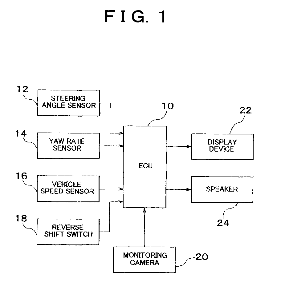
- the present vehicle-parking assisting system apparatus includes an electronic control unit (hereinafter abbreviated as "ECU") 10, which controls a display 22 and a sound generating device in the form of a speaker 24. These devices 22, 24 are provided to assist the vehicle operator when the vehicle is moved backwards, as described below.
- ECU electronice control unit
- the present vehicle-parking assisting system further includes a steering angle sensor 12, a yaw rate sensor 14 and a vehicle speed sensor 16, which are connected to the ECU 10.
- the steering angle sensor 12 generates an output signal representative of a steering angle ⁇ of a steering wheel operable by the vehicle operator.
- the yaw rate sensor 14 generates an output signal representative of a angular velocity about the gravity center of the vehicle, namely, a yaw rate ⁇ of the vehicle.
- the vehicle speed sensor 16 generates a pulse signal the period of which represents a running speed SPD of the vehicle.
- the output signals of the steering angle sensor 12, yaw rate sensor 14 and vehicle speed sensor 16 are fed to the ECU 10.
- the ECU 10 calculates the steering angle ⁇ on the basis of the output signal of the steering angle sensor 12, and calculates the yaw rate ⁇ about the gravity center of the vehicle on the basis of the output signal of the yaw rate sensor 14.
- the ECU 10 further calculates the vehicle running speed SPD of the vehicle on the basis of the output signal of the vehicle speed sensor 16.
- the ECU 10 estimates an actual turning radius R of the vehicle.
- a REVERSE SHIFT switch 18 which is placed in its ON state when a manually operable shift lever for a transmission is placed in a REVERSE position, and is placed in its OFF state when the shift lever is placed in any one of the other operating positions.
- the ECU 10 determines whether the vehicle is being moved backwards.
- a monitoring camera 20 disposed at a central part of a rear portion of the vehicle, and the above-indicated display device 22 and speaker 24.
- the display device 22 is disposed within an operator's compartment of the vehicle.
- the monitoring camera 20 is arranged to take a rear view, which is a view as seen from the vehicle in the backward direction. Visual information in the form of image data representative of the rear view are fed from the monitoring camera 20 to the ECU 10.
- the ECU 10 determines that the vehicle is being moved backwards, the ECU 10 commands the monitoring display 22 to display the rear view represented by image data received from the monitoring camera 20.
- the ECU 10 commands the speaker 24 to provide audio information in the form of voice messages, when a desired path of initial backward movement of the vehicle determined as described below is superimposed on the rear view displayed on a display screen of the display device 22, under the control of the ECU 10, during an initial portion of the backward movement of the vehicle to the desired parking area.
- Fig. 2 there will be described a method of determining the desired path of initial backward movement of the vehicle 50 toward the desired parking area, that is, the desired path along which the vehicle 50 is initially moved backwards for parking in the desired parking area which is open on only one side (on the right side as seen in Fig. 2) and which has a relatively short dimension as measured in the longitudinal direction of the vehicle 50 as parked therein.
- Fig. 2 the desired path along which the vehicle 50 is initially moved backwards for parking in the desired parking area which is open on only one side (on the right side as seen in Fig. 2) and which has a relatively short dimension as measured in the longitudinal direction of the vehicle 50 as parked therein.
- the desired paths of initial backward movements of the vehicle 50 for parking into rear left or right parking areas can be determined in substantially the same manner.
- the method of determining the desired path of initial backward movement of the vehicle 50 for parking into the rear left parking area by way of example.
- the vehicle 50 has steerable front left and right wheels FL, FR whose steering angle can be changed by the steering wheel, and non-steerable rear left and right wheels RL, RR.
- A denotes an axially intermediate point (hereinafter referred to as "rear-axle intermediate point") of a rear axle operatively connected to the rear wheels RL, RR, and "A 0 " denotes a position of the rear-axle intermediate point A of the vehicle 50 0 , that is, when the vehicle 50 is located at the initial position.
- a 1 denotes a position of the rear-axle intermediate point A of the vehicle 50 1 , that is, when the vehicle 50 is located at the parking position
- B 1 denotes a position of one of the rear wheels RL, RR at the parking position of the vehicle 50, which one rear wheel is located on the side corresponding to the side on which the parking area is not open.
- B 1 denotes the position of the rear left wheel RL.
- a path of movement of the rear-axle intermediate point A when the vehicle 50 is slowly moved forward from the parking position with the maximum angle of steering of the steerable front wheels FL, FR in the right direction is indicated by a broken line.
- this circular arc path originating from the position A 1 has the smallest turning radius R min of the vehicle 50, as also indicated in Fig. 2.
- a straight line (also indicated by a broken line) passing the position B 1 of the rear left wheel RL at the parking position is tangent to the above-indicated arcuate path of movement of the rear-axle intermediate point A, at a point C 1 (point of tangency C 1 ) which is located near the front_ right wheel FR at the parking position of the vehicle 50.
- the rear wheel RL having the position B 1 is located on the side of the vehicle 50 opposite to the side to which the vehicle 50 is turned (rightwards) along the above-indicated arcuate path having the radius R min , with the maximum angle of steering of the front wheels FL, FR in the right direction.
- the front wheel FR located near the point of_ tangency C1 is located on the side of the vehicle 50 to which the vehicle is turned along the above-indicated arcuate path having the radius R min .
- the desired path of initial backward movement of the rear-axle intermediate point A from the position A 0 to the position A 1 is determined to end at the point of tangency C 1 , at which the steering direction of the steering wheel (front wheels FL, FR) is reversed, that is, changed from the clockwise direction to the counterclockwise direction_ during the backward movement of the vehicle 50 from the initial position to the parking position.
- the above-indicated desired path of initial movement of the rear-axle intermediate point A from the position A 0 to the point of tangency C 1 consists of an arcuate path C 1 -A 0 of the point A which passes the point of tangency C 1 and the position A 0 of the point A at the initial_ position of the vehicle 50.
- the arcuate path C 1 -A 0 which is indicated by a solid line in Fig. 2, has a radius R1 larger than a radius of an arcuate path (not shown) which is tangent to the above-indicated arcuate path having the smallest turning radius R min and which passes the position A 0 of the rear-axle intermediate point A at the initial position of the vehicle 50.
- the arcuate path having the radius is used in the conventional system, as described before.
- the vehicle 50 is guided such that the rear-axle intermediate point A is initially moved along the above-indicated arcuate path A 0 -C 1 having the relatively large radius R1, until the point A has reached the point of tangency C 1 , that is, until the point A has reached a changeover or reversal point at which the steering direction is reversed or switched.
- the relatively large radius R1 is effective to reduce the amount of change of the longitudinal direction of the vehicle 50 in the horizontal plane in the initial portion of the backward movement of the vehicle 50 from the initial position toward the parking area.
- the use of the point of tangency C 1 as the changeover point of the steering direction of the vehicle 50 not only reduces the amount of change of the longitudinal direction of the vehicle 50 and accordingly the degree in which the vehicle operator feels uneasy with the change of the longitudinal direction of the vehicle 50, but also reduces the distance of partial protrusion of the parked vehicle 50 1 beyond the outer edge of the desired parking area.
- the vehicle-parking assisting system is characterized by the ECU 10 arranged to determine the desired path of initial backward movement of the vehicle 50 (more specifically, the rear-axle intermediate point A) from the initial position toward the parking position, so that the determined desired path of initial backward movement is displayed on the display device 22.
- the ECU 10 arranged to determine the desired path of initial backward movement of the vehicle 50 (more specifically, the rear-axle intermediate point A) from the initial position toward the parking position, so that the determined desired path of initial backward movement is displayed on the display device 22.
- control routine executed by the ECU 10 to determine the desired path of initial backward movement of the vehicle 50 upon parking of the vehicle in the desired parking area, and display the determined desired path on the display device 22.
- the control routine of Fig. 3 is executed each time a backward movement of the vehicle 50 for parking is detected.
- the control routine is initiated with step 100.
- Step 100 is formulated to determine the parking position of the vehicle 50, more precisely, the desired position A 1 to which the rear-axle intermediate point A is moved when the vehicle 50 is moved backwards for parking into the desired parking area, under the operator's manipulation of the vehicle.
- Step 100 is followed by step 102 to calculate the above-indicated arcuate path of the rear-axle intermediate point A which has the smallest vehicle turning radius R min and which is to be taken when the vehicle 50 is moved forward from the parking position (desired position A 1 ) with the maximum angle of steering of the steerable front wheels FL, FR in the right direction.
- the thus calculated arcuate path having the smallest turning radius R min is indicated by broken line in Fig. 2.
- step 104 the control flow goes to step 104 to calculate the point of tangency C 1 at which the straight line passing or extending from the position B 1 of the rear left wheel RL nearer to the side wall of the parking area is tangent to the arcuate path having the smallest turning radius R min , which has been calculated in step 102.
- Step 104 is followed by step 106 to calculate the above-indicated arcuate path A 0 -C 1 of the rear-axle intermediate point A which passes the point of tangency C 1 (calculated in step 104) and which is to be taken when the vehicle 50 is turned backwards from the initial position toward the parking area, in the initial portion of the backward movement of the vehicle 50 for parking in the parking area.
- the arcuate path A 0 -C 1 which passes the position A 0 and the point of tangency C 1 is obtained as an arc of a circle having a center which is located at a point of intersection between a straight line of extension (indicated by broken line in Fig.
- the arcuate path A 0 -C 1 calculated in step 106 has the radius R1, as indicated in Fig. 2.
- Step 108 is then implemented to display the arcuate path A 0 -C 1 on the display device 22, as the desired path of movement of the rear-axle intermediate point A in an initial portion of the backward movement of the vehicle 50 from the initial position to the parking position.
- the vehicle operator may utilize the visual information given on the display device 22, which assists the operator in manipulating the steering wheel for guiding the vehicle 50 into the parking area, along the desired path.
- the control routine of Fig. 3 is terminated with step 108.
- the present vehicle-parking assisting system is arranged to determine the desired path of backward movement of a selected portion (rear-axle intermediate point A) of the vehicle 50, which path passes a predetermined position (point of tangency C 1 ) which is determined by characteristics of turning movement of the vehicle 50 from the parking position, more specifically, by the position A 1 of the point A at the parking position and the arcuate path of turning of the vehicle 50 from the parking position with the smallest turning radius R min .
- the assisting system is further arranged to control the display device 22 to display the thus determined desired path of backward movement of the selected portion of the vehicle 50.
- the vehicle operator observing the displayed desired path of backward movement can suitably manipulate the steering wheel so that the actual path of backward movement follows the desired path.
- the present assisting system effectively assists the vehicle operator in performing the steering operation of the vehicle 50 for suitably guiding the vehicle into the desired parking area, even where the backward movement of the vehicle into the parking area involves a relatively large distance of lateral movement of the vehicle during a relatively small distance of longitudinal movement of the vehicle.
- the ECU 10 commands the speaker 24 to generate a voice message informing the vehicle operator of this fact.
- the ECU 10 commands the speaker 24 to generate another voice message informing the operator of this fact, so that the operator may stop the vehicle 50 at the point of tangency C 1 , and then turn the steering wheel all the way in the reverse direction (in the clockwise direction in the example of Fig. 2), for maximum angle of steering of the front wheels FL, FR in the corresponding direction.
- the subsequent backward movement of the vehicle 50 from the point of tangency C 1 is initiated so that the rear-axle intermediate point A is eventually moved to the position A 1 at the parking position, along the arcuate path C 1 -A 1 which has the smallest turning radius R min .
- the present embodiment is arranged to display only the arcuate path A 0 -C 1 as the desired path of initial backward movement of the point A, on the display device 22, as indicated by the solid line in Fig. 2, it will be understood that the desired path of the entire backward movement of the point A from the position A 0 to the position A 1 may be displayed, that is, both the arcuate path A 0 -C 1 and the arcuate path C 1 -A 1 may be displayed on the display device 22.
- the point of tangency C 1 is used as the changeover point at which the steering direction of the steering wheel (the front wheels FL, FR) is reversed during the backward movement of the vehicle 50 into the parking area.
- this point of tangency C 1 is located near one of the two front wheels FL, FR which is on the side corresponding to the direction of turning of the vehicle 50 from the parking position along the above-indicated arcuate path A 1 -C 1 having the smallest turning radius Rmin .
- the point of tangency C 1 is located near the front right wheel FR located on the right side corresponding to the clockwise turning of the path A 1 -C 1 .
- the radius R1 of the arcuate path A 0 -C 1 which passes the position A0 of the point A at the initial position of the vehicle 50 and the point of tangency C 1 is larger than the conventional radius R2 of the arcuate path which passes the position A 0 and which is tangent to the above-indicated arcuate path A 1 -C 1 which has the smallest turning radius R min .
- the radius R1 is considerably larger than the conventionally used radius R2 where the distance of movement of the vehicle 50 from the initial position (position A 0 ) to the parking position (position A 1 ) is relatively large.
- the present embodiment arranged to display the desired path of initial backward movement of the vehicle 50 on the display device 22 permits a reduced possibility that the vehicle operator feels uneasy with a relatively large amount of change of the longitudinal direction of the vehicle 50. Further, the present embodiment is effective to prevent a large distance of partial protrusion of the vehicle 50 beyond the outer side edge of the parking area.
- the present embodiment enables the vehicle operator to manipulate the steering wheel for parking the vehicle 50 in the desired parking area so that the parked vehicle does not disturb smooth passage of the other vehicles, while preventing the vehicle operator from feeling uneasy with a change of the longitudinal direction of the vehicle 50 during the initial portion of its backward movement.
- the present embodiment which permits the vehicle 50 to be initially moved backwards along an arcuate path having a comparatively large radius, has a further advantage that the friction between the wheels and the road surface is made smaller than in the conventional arrangement using the desired arcuate path having a comparatively small radius, with a result of a reduced assisting force required to operate the front wheels FL, FR and an accordingly improved fuel economy of the vehicle 50.
- the first embodiment described above is adapted to calculate the arcuate path of the rear-axle intermediate point A from the position A 0 , which is to be taken when the vehicle 50 is turned forward from the parking position with the smallest turning radius R min .
- the first embodiment is further adapted to calculate the point of tangency C 1 between the calculated arcuate path and the straight line passing the position B 1 of the rear left wheel RL.
- the point of tangency C 1 is used as the changeover point at which the steering direction is reversed.
- the present second embodiment is adapted to first calculate an arcuate path of movement of the rear-axle intermediate point A of the vehicle body that is to be taken when the vehicle 50 is turned forward with the smallest turning radius.
- This arcuate path is calculated when the assisting apparatus is initially turned on.
- the second embodiment is further adapted to calculate a point C at which the straight line passing a predetermined one of the rear wheels is tangent to the calculated arcuate path.
- This point of tangency C is defined relative to the body of the vehicle, and is used as the changeover point at which the steering direction is reversed when the vehicle is turned backwards into the parking area. Namely, the point of tangency C located within the vehicle body when the vehicle 50 is at the parking position is set as the changeover point.
- the present second embodiment eliminates a need of calculating the arcuate path of the point A and the point of tangency C 1 which are located within the parking area, each time the vehicle 50 is moved backwards into the parking area. Accordingly, the present second embodiment makes it possible to reduce the load of the ECU 10 to determine the changeover point of the steering direction upon backward movements of the vehicle 50 into the parking area. Further, the time required to determine the changeover point can be reduced in the present embodiment.
- the flow chart of Fig. 4 illustrates a control routine executed by the ECU 10 to determine and store the point of tangency C, when initial setting of the vehicle-parking assisting apparatus is effected.
- This control routine of Fig. 4 is initiated with step 120.
- Step 120 is formulated to determine the arcuate path of the rear-axle intermediate point A that is to be taken when the vehicle 50 is turned forward with the maximum steering angle of the front wheels FL, FR.
- Step 120 is followed by step 122 to calculate the point of tangency C at which the straight line passing or extending from the position B of one of the rear wheels RL, RR is tangent to the arcuate path having the smallest turning radius R min , which has been calculated in step 120.
- the rear wheel RL having the position B is located on the side of the vehicle 50 opposite to the side to which the vehicle 50 is turned along the above-indicated arcuate path having the radius R min , with the maximum angle of steering of the front wheels FL, FR.
- step 124 is implemented to store the point of tangency C (calculated in step 122) which is defined relative to the vehicle body.
- the point of tangency C stored in the ECU 10 upon initial setting of the assisting apparatus is located within the vehicle body and is used as a reference point set on the vehicle body.
- This reference point or tangency point C is used as the changeover point C 1 of the steering direction when the vehicle 50 is moved backwards into the parking area.
- Fig. 5 there is shown an example of the control routine which is executed by the ECU 10 to determine the desired path of initial backward movement of the vehicle 50 from the initial position toward the parking position, and display the determined desired path on the display device 22.
- the same reference numerals as used in Fig. 3 are used to identify the same steps.
- the first step 100 for determining the parking position is followed by step 140.
- Step 140 is formulated to calculate a desired path of initial backward movement of the rear-axle intermediate point A when the vehicle 50 is initially moved backwards from the initial position toward the determined parking position. As in the first embodiment, this desired path of initial backward movement ends with the changeover point C 1 of the steering direction, which point C 1 is obtained on the basis of the point of tangency C stored in the memory. After step 140 is implemented to calculate the desired path of initial backward movement, step 108 is implemented or executed to display the calculated desired path of initial backward movement on the display device 22.
- the second embodiment is arranged to determine the desired path of initial backward movement of the selected portion of the vehicle body, such that the desired path passes a predetermined position (changeover point C 1 obtained from the stored point of tangency C) which is determined by the turning characteristics of the vehicle 50 at the parking position.
- the thus determined desired path of initial backward movement is displayed on the display device 22, for assisting the vehicle operator to suitably guide the vehicle 50 into the desired parking area, as in the first embodiment.
- the second embodiment is characterized in that the ECU 10 operates, before initiation of backward movement of the vehicle 50 for parking in the parking area, to obtain the point of tangency C between the arcuate path to be taken by the rear-axle intermediate point A when the vehicle 50 is moved forwards with the smallest turning radius, and the straight line which passes one of the rear wheels.
- This point of tangency C defined relative to the vehicle body is used to determine the changeover point C 1 located within the parking area, when the vehicle 50 is actually moved backward into the parking area.
- the present second embodiment does not require to calculate the above-indicated arcuate path having the smallest turning radius and the point of tangency C, each time the vehicle 50 is moved backwards for parking in the parking area, so that the load of the ECU 10 to calculate the changeover point C 1 is reduced, with a result of reducing the time required to calculate the changeover point.
- the principle of the present invention is equally applicable to an automotive vehicle having non-steerable front wheels FL, FR and steerable rear wheels RL, RR, and an automotive vehicle having four steerable wheels FL, FR, RL, RR.
- the illustrated first and second embodiments are arranged display the calculated desired path of movement of the vehicle on the display device 22, for the purpose of assisting the vehicle operator in suitably manipulating the steering wheel so as to guide the vehicle into the desired parking area.
- the desired path of movement may be used to automatically control the steering system so as to guide the vehicle into the parking area, without the vehicle operator's manipulation of the steering wheel, or a haptic information by adequately supporting the turning of the steering wheel may be provided to the vehicle operator.
- the apparatus is considered to assist the vehicle operator in guiding the vehicle from the initial position to the parking position.
- the assisting system includes a control device operable to (a) calculate an arcuate path of movement of a first selected portion (A) of the vehicle that is to be taken when the vehicle is turned from the parking position with a smallest turning radius (R min ), (b) calculate a point of tangency (C 1 ) between the calculated arcuate path of movement and a straight line passing a second selected portion (B 1 ) of the vehicle when the vehicle is located at the parking position, (c) determine a desired path of movement of the first selected portion from the initial position toward the parking position, which desired path passes the point of tangency, and (d) display the determined desired path of movement on a display device (22).
Landscapes
- Engineering & Computer Science (AREA)
- Transportation (AREA)
- Mechanical Engineering (AREA)
- Chemical & Material Sciences (AREA)
- Combustion & Propulsion (AREA)
- Multimedia (AREA)
- Radar, Positioning & Navigation (AREA)
- Remote Sensing (AREA)
- Human Computer Interaction (AREA)
- Steering Control In Accordance With Driving Conditions (AREA)
- Control Of Driving Devices And Active Controlling Of Vehicle (AREA)
Abstract
Description
- The present invention relates in general to a vehicle-parking assisting system, and more particularly to a system arranged to assist an operator of a vehicle upon parking of the vehicle in a desired parking area, by providing audio-visual information such as voice messages and displayed images, and effecting automatic control of a steering system of the vehicle, so that the vehicle can be easily guided into the desired parking area, even when the parking area is open on only one side thereof, for instance, when the parking area is located between two other vehicles already parked with a relatively short spacing therebetween.
- JP-A-64-65412 discloses an example of a known method of guiding a vehicle to a desired position. In this method, a path of movement of the vehicle from a present position to the desired position includes a circular arc of a first circle having a radius not smaller than the smallest turning radius of the vehicle, and a circular arc of a second circle which has a radius not smaller than the smallest turning radius and which is tangent to the first circle at a point from which the above-indicated circular arcs extend toward the present and desired positions. This known method permits easy guiding of the vehicle to the desired position.
- Where the known method indicated above is practiced when the vehicle is parked into a parking area, with a comparatively long movement of the vehicle in its lateral direction during a comparatively short movement of the vehicle in its longitudinal direction, the longitudinal direction of the vehicle may vary by a relatively large angle in the horizontal plane. Namely, the longitudinal direction of the vehicle may become considerably different from a direction of extension of a straight line_ connecting the present position and the desired parking area (desired position to which the vehicle is guided), during the movement to the desired parking area or position. This difference may make the vehicle operator feel uneasy. In addition, the known method tends to suffer from an insufficient distance of movement of the vehicle in the lateral direction, resulting in a large amount of partial protrusion of the parked vehicle beyond the outer edge of the desired parking area, which disturbs passage of other vehicles alongside the parked vehicle.
- The present invention was made in view of the related art described above. It is therefore an object of the present invention to provide a vehicle-parking assisting system which permits a reduced amount of change of the longitudinal direction of the vehicle in the horizontal plane, upon parking of a vehicle involving a comparatively large distance of movement in its lateral direction during a comparatively small distance of movement in its longitudinal direction.
- A predetermined position is determined by the characteristics of turning of the vehicle located at the parking position, irrespective of the initial position of the vehicle. The desired path of movement of the first selected portion of the vehicle from the initial position toward the parking position is determined such that the desired path of movement passes the predetermined position at which the steering direction of the steerable wheel of the vehicle is reversed during a movement of the vehicle from the initial position to the parking position. The present vehicle-parking assisting system permits a smaller amount of change of the longitudinal direction of the vehicle in the horizontal plane, even when the parking involves a comparatively large distance of lateral movement of the vehicle between the initial and parking positions, as compared with an assisting system wherein the changeover point at which the steering direction is reversed is determined by the initial position from which the vehicle is moved for parking.
- In the present invention, the term "assisting an operator of a vehicle upon parking of the vehicle into a desired parking area" is interpreted to mean (i) assisting the vehicle operator in manipulating the steering wheel of the vehicle, by providing audio-visual information regarding the desired path of movement of the vehicle to the parking position, such as a displayed image of the desired path and/or a voice message, or alternatively (ii) assisting the vehicle operator by effecting an automatic control of the steering system of the vehicle so that the vehicle is moved along the desired path from the initial position to the parking position. Further a semi-automatic alternative or option (i) and (ii) is an automatic support control of the steering system which_ provides haptic information to the vehicle operator by supporting/obstructing the movement of the steering wheel in the correct/incorrect direction such that the vehicle operator must then only follow the easier moving direction of the wheel.
- The predetermined position indicated above may be determined on the basis of the arcuate path of movement of the first selected portion of the vehicle that is to be taken when the vehicle is moved from the parking position with the smallest turning radius, and the straight line which passes the second selected portion of the vehicle at the parking position. Alternatively, the predetermined position may be determined on the basis of a reference position defined relative to the vehicle body, which reference position is determined on the basis of the arcuate path of movement of the first selected portion that is to be taken when the vehicle is turned with the smallest turning radius, and the straight line passing the second selected portion of the vehicle. In this latter case, the reference position which is defined relative to the vehicle body and which does not lie on the desired path of movement of the first selected portion of the vehicle is converted into the predetermined position lying on the desired path of movement of the first selected portion.
- In the illustrated first and second embodiments which will be described in detail, the axially intermediate point A of the rear axle connected to the rear wheels RL, RR is equivalent to the first selected portion of the vehicle and a rear axle connected to two rear wheels of the vehicle, which are recited in the claims. Further, the position of the rear left wheel RL or rear right wheel RR is equivalent to the second selected portion of the vehicle recited in the claims. The point of tangency C1 is equivalent to the predetermined position and the changeover point which are recited in the claims.
- In the present invention, the predetermined position which serves as the changeover point at which the steering direction of the vehicle is reversed is determined on the basis of the characteristics of turning of the vehicle located at the parking position. The desired path of movement of the first selected portion of the vehicle from the initial position is terminated at the thus determined changeover point.
- The above and other objects, features, advantages, and technical and industrial significance of this invention will be better understood by reading the following detailed description of exemplary embodiments of the invention, when considered in connection with the accompanying drawings, in which:
- Fig. 1 is a block diagram illustrating a vehicle-parking assisting system constructed according to a first embodiment of this invention;
- Fig. 2 is a view for explaining a method of determining a path of movement of an automotive vehicle to a parking area in the first embodiment;
- Fig. 3 is a flow chart illustrating one example of a control routine executed in the first embodiment, to control a display device, for displaying the path of movement of the vehicle to the parking area;
- Fig. 4 is a flow chart illustrating one example of a control routine executed to obtain and store a reference point with respect to the vehicle body, according to a second embodiment of the present invention; and
- Fig. 5 is a flow chart illustrating an example of a control routine executed in the second embodiment, to control the display device, for displaying the path of movement of the vehicle to the parking area.
-
- Referring first to Fig. 1, there is shown a vehicle-parking assisting system constructed according to the first embodiment of this invention, for assisting an operator of an automotive vehicle upon parking of the vehicle in a desired parking area, which involves a comparatively large distance of lateral movement of the vehicle during a comparatively short distance of longitudinal movement of the vehicle from the present position.
- The present vehicle-parking assisting system apparatus includes an electronic control unit (hereinafter abbreviated as "ECU") 10, which controls a
display 22 and a sound generating device in the form of aspeaker 24. Thesedevices - The present vehicle-parking assisting system further includes a
steering angle sensor 12, ayaw rate sensor 14 and avehicle speed sensor 16, which are connected to theECU 10. Thesteering angle sensor 12 generates an output signal representative of a steering angle of a steering wheel operable by the vehicle operator. Theyaw rate sensor 14 generates an output signal representative of a angular velocity about the gravity center of the vehicle, namely, a yaw rate ω of the vehicle. Thevehicle speed sensor 16 generates a pulse signal the period of which represents a running speed SPD of the vehicle. - The output signals of the
steering angle sensor 12,yaw rate sensor 14 andvehicle speed sensor 16 are fed to theECU 10. TheECU 10 calculates the steering angle on the basis of the output signal of thesteering angle sensor 12, and calculates the yaw rate ω about the gravity center of the vehicle on the basis of the output signal of theyaw rate sensor 14. The ECU 10 further calculates the vehicle running speed SPD of the vehicle on the basis of the output signal of thevehicle speed sensor 16. On the basis of the thus calculated steering angle , yaw rate ω and vehicle running speed SPD, theECU 10 estimates an actual turning radius R of the vehicle. - To the
ECU 10, there is also connected aREVERSE SHIFT switch 18, which is placed in its ON state when a manually operable shift lever for a transmission is placed in a REVERSE position, and is placed in its OFF state when the shift lever is placed in any one of the other operating positions. On the basis of the output signal of the REVERSESHIFT switch 18, theECU 10 determines whether the vehicle is being moved backwards. - To the
ECU 10, there are also connected amonitoring camera 20 disposed at a central part of a rear portion of the vehicle, and the above-indicateddisplay device 22 andspeaker 24. Thedisplay device 22 is disposed within an operator's compartment of the vehicle. Themonitoring camera 20 is arranged to take a rear view, which is a view as seen from the vehicle in the backward direction. Visual information in the form of image data representative of the rear view are fed from themonitoring camera 20 to theECU 10. When the ECU 10 determines that the vehicle is being moved backwards, theECU 10 commands themonitoring display 22 to display the rear view represented by image data received from themonitoring camera 20. - The
ECU 10 commands thespeaker 24 to provide audio information in the form of voice messages, when a desired path of initial backward movement of the vehicle determined as described below is superimposed on the rear view displayed on a display screen of thedisplay device 22, under the control of theECU 10, during an initial portion of the backward movement of the vehicle to the desired parking area. - Referring next to Fig. 2, there will be described a method of determining the desired path of initial backward movement of the
vehicle 50 toward the desired parking area, that is, the desired path along which thevehicle 50 is initially moved backwards for parking in the desired parking area which is open on only one side (on the right side as seen in Fig. 2) and which has a relatively short dimension as measured in the longitudinal direction of thevehicle 50 as parked therein. In Fig. 2, "500" denotes thevehicle 50 located at a position (hereinafter referred to as "initial position") at which the backward movement (turning) of thevehicle 50 for parking is initiated, while "501" denotes thevehicle 50 located at a position (hereinafter referred to as "parking position") at which the backward movement of thevehicle 50 for parking is terminated or completed. The backward movement of thevehicle 50 for parking into the parking area located rearwards and leftwards of thevehicle 50 as shown in Fig. 2 requires initial turning of the steering wheel in the counterclockwise direction, while the backward movement of thevehicle 50 for parking into the parking area located rearwards and rightwards of thevehicle 50 requires initial turning of the steering wheel in the clockwise direction. However, the desired paths of initial backward movements of thevehicle 50 for parking into rear left or right parking areas can be determined in substantially the same manner. In this respect, there will be described the method of determining the desired path of initial backward movement of thevehicle 50 for parking into the rear left parking area, by way of example. - In the present embodiment, the
vehicle 50 has steerable front left and right wheels FL, FR whose steering angle can be changed by the steering wheel, and non-steerable rear left and right wheels RL, RR. In Fig. 2, "A" denotes an axially intermediate point (hereinafter referred to as "rear-axle intermediate point") of a rear axle operatively connected to the rear wheels RL, RR, and "A0" denotes a position of the rear-axle intermediate point A of thevehicle 500, that is, when thevehicle 50 is located at the initial position. Further, "A1" denotes a position of the rear-axle intermediate point A of thevehicle 501, that is, when thevehicle 50 is located at the parking position, and "B1" denotes a position of one of the rear wheels RL, RR at the parking position of thevehicle 50, which one rear wheel is located on the side corresponding to the side on which the parking area is not open. In the specific example of Fig. 2, "B1" denotes the position of the rear left wheel RL. - In Fig. 2, a path of movement of the rear-axle intermediate point A when the
vehicle 50 is slowly moved forward from the parking position with the maximum angle of steering of the steerable front wheels FL, FR in the right direction is indicated by a broken line. Namely, this circular arc path originating from the position A1 has the smallest turning radius Rmin of thevehicle 50, as also indicated in Fig. 2. A straight line (also indicated by a broken line) passing the position B1 of the rear left wheel RL at the parking position is tangent to the above-indicated arcuate path of movement of the rear-axle intermediate point A, at a point C1 (point of tangency C1) which is located near the front_ right wheel FR at the parking position of thevehicle 50. In this example, the rear wheel RL having the position B1 is located on the side of thevehicle 50 opposite to the side to which thevehicle 50 is turned (rightwards) along the above-indicated arcuate path having the radius Rmin, with the maximum angle of steering of the front wheels FL, FR in the right direction. On the other hand, the front wheel FR located near the point of_ tangency C1 is located on the side of thevehicle 50 to which the vehicle is turned along the above-indicated arcuate path having the radius Rmin. In the present embodiment, the desired path of initial backward movement of the rear-axle intermediate point A from the position A0 to the position A1 is determined to end at the point of tangency C1, at which the steering direction of the steering wheel (front wheels FL, FR) is reversed, that is, changed from the clockwise direction to the counterclockwise direction_ during the backward movement of thevehicle 50 from the initial position to the parking position. The above-indicated desired path of initial movement of the rear-axle intermediate point A from the position A0 to the point of tangency C1 consists of an arcuate path C1-A0 of the point A which passes the point of tangency C1 and the position A0 of the point A at the initial_ position of thevehicle 50. The arcuate path C1-A0, which is indicated by a solid line in Fig. 2, has a radius R1 larger than a radius of an arcuate path (not shown) which is tangent to the above-indicated arcuate path having the smallest turning radius Rmin and which passes the position A0 of the rear-axle intermediate point A at the initial position of thevehicle 50. The arcuate path having the radius is used in the conventional system, as described before. - In the present embodiment, the
vehicle 50 is guided such that the rear-axle intermediate point A is initially moved along the above-indicated arcuate path A0-C1 having the relatively large radius R1, until the point A has reached the point of tangency C1, that is, until the point A has reached a changeover or reversal point at which the steering direction is reversed or switched. The relatively large radius R1 is effective to reduce the amount of change of the longitudinal direction of thevehicle 50 in the horizontal plane in the initial portion of the backward movement of thevehicle 50 from the initial position toward the parking area. Thus, the use of the point of tangency C1 as the changeover point of the steering direction of thevehicle 50 not only reduces the amount of change of the longitudinal direction of thevehicle 50 and accordingly the degree in which the vehicle operator feels uneasy with the change of the longitudinal direction of thevehicle 50, but also reduces the distance of partial protrusion of the parkedvehicle 501 beyond the outer edge of the desired parking area. - The vehicle-parking assisting system according to the present embodiment of the invention is characterized by the
ECU 10 arranged to determine the desired path of initial backward movement of the vehicle 50 (more specifically, the rear-axle intermediate point A) from the initial position toward the parking position, so that the determined desired path of initial backward movement is displayed on thedisplay device 22. The present embodiment will be further explained. - Referring to the flow chart of Fig. 3, there is illustrated one example of the control routine executed by the
ECU 10 to determine the desired path of initial backward movement of thevehicle 50 upon parking of the vehicle in the desired parking area, and display the determined desired path on thedisplay device 22. The control routine of Fig. 3 is executed each time a backward movement of thevehicle 50 for parking is detected. The control routine is initiated withstep 100. - Step 100 is formulated to determine the parking position of the
vehicle 50, more precisely, the desired position A1 to which the rear-axle intermediate point A is moved when thevehicle 50 is moved backwards for parking into the desired parking area, under the operator's manipulation of the vehicle. - Step 100 is followed by
step 102 to calculate the above-indicated arcuate path of the rear-axle intermediate point A which has the smallest vehicle turning radius Rmin and which is to be taken when thevehicle 50 is moved forward from the parking position (desired position A1) with the maximum angle of steering of the steerable front wheels FL, FR in the right direction. The thus calculated arcuate path having the smallest turning radius Rmin is indicated by broken line in Fig. 2. - Then, the control flow goes to step 104 to calculate the point of tangency C1 at which the straight line passing or extending from the position B1 of the rear left wheel RL nearer to the side wall of the parking area is tangent to the arcuate path having the smallest turning radius Rmin, which has been calculated in
step 102. - Step 104 is followed by
step 106 to calculate the above-indicated arcuate path A0-C1 of the rear-axle intermediate point A which passes the point of tangency C1 (calculated in step 104) and which is to be taken when thevehicle 50 is turned backwards from the initial position toward the parking area, in the initial portion of the backward movement of thevehicle 50 for parking in the parking area. Described in detail, the arcuate path A0-C1 which passes the position A0 and the point of tangency C1 is obtained as an arc of a circle having a center which is located at a point of intersection between a straight line of extension (indicated by broken line in Fig. 2) from the rear axle (having the axially intermediate point A0) and a straight line L1(indicated by broken line) which is perpendicular to and devides a straight line connecting the point of tangency C1 and the position A0 of the rear-axle intermediate point A at the initial position by half. The arcuate path A0-C1 calculated instep 106 has the radius R1, as indicated in Fig. 2. - Step 108 is then implemented to display the arcuate path A0-C1 on the
display device 22, as the desired path of movement of the rear-axle intermediate point A in an initial portion of the backward movement of thevehicle 50 from the initial position to the parking position. After thestep 108 is initiated, the vehicle operator may utilize the visual information given on thedisplay device 22, which assists the operator in manipulating the steering wheel for guiding thevehicle 50 into the parking area, along the desired path. The control routine of Fig. 3 is terminated withstep 108. - As described above, the present vehicle-parking assisting system is arranged to determine the desired path of backward movement of a selected portion (rear-axle intermediate point A) of the
vehicle 50, which path passes a predetermined position (point of tangency C1) which is determined by characteristics of turning movement of thevehicle 50 from the parking position, more specifically, by the position A1 of the point A at the parking position and the arcuate path of turning of thevehicle 50 from the parking position with the smallest turning radius Rmin. The assisting system is further arranged to control thedisplay device 22 to display the thus determined desired path of backward movement of the selected portion of thevehicle 50. Accordingly, the vehicle operator observing the displayed desired path of backward movement can suitably manipulate the steering wheel so that the actual path of backward movement follows the desired path. Thus, the present assisting system effectively assists the vehicle operator in performing the steering operation of thevehicle 50 for suitably guiding the vehicle into the desired parking area, even where the backward movement of the vehicle into the parking area involves a relatively large distance of lateral movement of the vehicle during a relatively small distance of longitudinal movement of the vehicle. - When the rear-axle intermediate point A has been moved with the
vehicle 50 along the desired path of initial backward movement, to a position near the point of tangency C1, theECU 10 commands thespeaker 24 to generate a voice message informing the vehicle operator of this fact. When the point A has reached the point of tangency C1, theECU 10 commands thespeaker 24 to generate another voice message informing the operator of this fact, so that the operator may stop thevehicle 50 at the point of tangency C1, and then turn the steering wheel all the way in the reverse direction (in the clockwise direction in the example of Fig. 2), for maximum angle of steering of the front wheels FL, FR in the corresponding direction. In this state the subsequent backward movement of thevehicle 50 from the point of tangency C1 is initiated so that the rear-axle intermediate point A is eventually moved to the position A1 at the parking position, along the arcuate path C1-A1 which has the smallest turning radius Rmin. Although the present embodiment is arranged to display only the arcuate path A0-C1 as the desired path of initial backward movement of the point A, on thedisplay device 22, as indicated by the solid line in Fig. 2, it will be understood that the desired path of the entire backward movement of the point A from the position A0 to the position A1 may be displayed, that is, both the arcuate path A0-C1 and the arcuate path C1-A1 may be displayed on thedisplay device 22. - In the present embodiment described above, the point of tangency C1 is used as the changeover point at which the steering direction of the steering wheel (the front wheels FL, FR) is reversed during the backward movement of the
vehicle 50 into the parking area. As described above, this point of tangency C1 is located near one of the two front wheels FL, FR which is on the side corresponding to the direction of turning of thevehicle 50 from the parking position along the above-indicated arcuate path A1-C1 having the smallest turning radius Rmin. In the specific example of Fig. 2, the point of tangency C1 is located near the front right wheel FR located on the right side corresponding to the clockwise turning of the path A1-C1. With the point of tangency C1 thus located, the radius R1 of the arcuate path A0-C1 which passes the position A0 of the point A at the initial position of thevehicle 50 and the point of tangency C1 is larger than the conventional radius R2 of the arcuate path which passes the position A0 and which is tangent to the above-indicated arcuate path A1-C1 which has the smallest turning radius Rmin. The radius R1 is considerably larger than the conventionally used radius R2 where the distance of movement of thevehicle 50 from the initial position (position A0) to the parking position (position A1) is relatively large. - When the
vehicle 50 is turned from the initial position to the changeover point (point of tangency C1) along an arcuate path having a comparatively large radius, a large amount of change of the longitudinal direction of thevehicle 50 can be prevented, that is, the amount of change of the longitudinal direction can be made relatively small. Accordingly, the present embodiment arranged to display the desired path of initial backward movement of thevehicle 50 on thedisplay device 22 permits a reduced possibility that the vehicle operator feels uneasy with a relatively large amount of change of the longitudinal direction of thevehicle 50. Further, the present embodiment is effective to prevent a large distance of partial protrusion of thevehicle 50 beyond the outer side edge of the parking area. Thus, the present embodiment enables the vehicle operator to manipulate the steering wheel for parking thevehicle 50 in the desired parking area so that the parked vehicle does not disturb smooth passage of the other vehicles, while preventing the vehicle operator from feeling uneasy with a change of the longitudinal direction of thevehicle 50 during the initial portion of its backward movement. - The present embodiment, which permits the
vehicle 50 to be initially moved backwards along an arcuate path having a comparatively large radius, has a further advantage that the friction between the wheels and the road surface is made smaller than in the conventional arrangement using the desired arcuate path having a comparatively small radius, with a result of a reduced assisting force required to operate the front wheels FL, FR and an accordingly improved fuel economy of thevehicle 50. - There will next be described a second embodiment of the present invention.
- The first embodiment described above is adapted to calculate the arcuate path of the rear-axle intermediate point A from the position A0, which is to be taken when the
vehicle 50 is turned forward from the parking position with the smallest turning radius Rmin. The first embodiment is further adapted to calculate the point of tangency C1 between the calculated arcuate path and the straight line passing the position B1 of the rear left wheel RL. In the first embodiment, the point of tangency C1 is used as the changeover point at which the steering direction is reversed. - On the other hand, the present second embodiment is adapted to first calculate an arcuate path of movement of the rear-axle intermediate point A of the vehicle body that is to be taken when the
vehicle 50 is turned forward with the smallest turning radius. This arcuate path is calculated when the assisting apparatus is initially turned on. The second embodiment is further adapted to calculate a point C at which the straight line passing a predetermined one of the rear wheels is tangent to the calculated arcuate path. This point of tangency C is defined relative to the body of the vehicle, and is used as the changeover point at which the steering direction is reversed when the vehicle is turned backwards into the parking area. Namely, the point of tangency C located within the vehicle body when thevehicle 50 is at the parking position is set as the changeover point. The present second embodiment eliminates a need of calculating the arcuate path of the point A and the point of tangency C1 which are located within the parking area, each time thevehicle 50 is moved backwards into the parking area. Accordingly, the present second embodiment makes it possible to reduce the load of theECU 10 to determine the changeover point of the steering direction upon backward movements of thevehicle 50 into the parking area. Further, the time required to determine the changeover point can be reduced in the present embodiment. - Referring to Figs. 4 and 5, the second embodiment will be described in detail.
- The flow chart of Fig. 4 illustrates a control routine executed by the
ECU 10 to determine and store the point of tangency C, when initial setting of the vehicle-parking assisting apparatus is effected. This control routine of Fig. 4 is initiated withstep 120. - Step 120 is formulated to determine the arcuate path of the rear-axle intermediate point A that is to be taken when the
vehicle 50 is turned forward with the maximum steering angle of the front wheels FL, FR. - Step 120 is followed by
step 122 to calculate the point of tangency C at which the straight line passing or extending from the position B of one of the rear wheels RL, RR is tangent to the arcuate path having the smallest turning radius Rmin, which has been calculated instep 120. The rear wheel RL having the position B is located on the side of thevehicle 50 opposite to the side to which thevehicle 50 is turned along the above-indicated arcuate path having the radius Rmin, with the maximum angle of steering of the front wheels FL, FR. - Then, step 124 is implemented to store the point of tangency C (calculated in step 122) which is defined relative to the vehicle body.
- In the second embodiment, the point of tangency C stored in the
ECU 10 upon initial setting of the assisting apparatus is located within the vehicle body and is used as a reference point set on the vehicle body. This reference point or tangency point C is used as the changeover point C1 of the steering direction when thevehicle 50 is moved backwards into the parking area. - Referring next to the flow chart of Fig. 5, there is shown an example of the control routine which is executed by the
ECU 10 to determine the desired path of initial backward movement of thevehicle 50 from the initial position toward the parking position, and display the determined desired path on thedisplay device 22. In Fig. 5, the same reference numerals as used in Fig. 3 are used to identify the same steps. In the control routine of Fig. 5, thefirst step 100 for determining the parking position is followed bystep 140. - Step 140 is formulated to calculate a desired path of initial backward movement of the rear-axle intermediate point A when the
vehicle 50 is initially moved backwards from the initial position toward the determined parking position. As in the first embodiment, this desired path of initial backward movement ends with the changeover point C1 of the steering direction, which point C1 is obtained on the basis of the point of tangency C stored in the memory. Afterstep 140 is implemented to calculate the desired path of initial backward movement,step 108 is implemented or executed to display the calculated desired path of initial backward movement on thedisplay device 22. - Like the first embodiment, the second embodiment is arranged to determine the desired path of initial backward movement of the selected portion of the vehicle body, such that the desired path passes a predetermined position (changeover point C1 obtained from the stored point of tangency C) which is determined by the turning characteristics of the
vehicle 50 at the parking position. The thus determined desired path of initial backward movement is displayed on thedisplay device 22, for assisting the vehicle operator to suitably guide thevehicle 50 into the desired parking area, as in the first embodiment. - The second embodiment is characterized in that the
ECU 10 operates, before initiation of backward movement of thevehicle 50 for parking in the parking area, to obtain the point of tangency C between the arcuate path to be taken by the rear-axle intermediate point A when thevehicle 50 is moved forwards with the smallest turning radius, and the straight line which passes one of the rear wheels. This point of tangency C defined relative to the vehicle body is used to determine the changeover point C1 located within the parking area, when thevehicle 50 is actually moved backward into the parking area. Accordingly, the present second embodiment does not require to calculate the above-indicated arcuate path having the smallest turning radius and the point of tangency C, each time thevehicle 50 is moved backwards for parking in the parking area, so that the load of theECU 10 to calculate the changeover point C1 is reduced, with a result of reducing the time required to calculate the changeover point. - While the first and second embodiments which have been described are applied to the
automotive vehicle 50 having the steerable front wheels FL, FR and the non-steerable rear wheels RL, RR, the principle of the present invention is equally applicable to an automotive vehicle having non-steerable front wheels FL, FR and steerable rear wheels RL, RR, and an automotive vehicle having four steerable wheels FL, FR, RL, RR. - The illustrated first and second embodiments are arranged display the calculated desired path of movement of the vehicle on the
display device 22, for the purpose of assisting the vehicle operator in suitably manipulating the steering wheel so as to guide the vehicle into the desired parking area. However, the desired path of movement may be used to automatically control the steering system so as to guide the vehicle into the parking area, without the vehicle operator's manipulation of the steering wheel, or a haptic information by adequately supporting the turning of the steering wheel may be provided to the vehicle operator. In this case, too, the apparatus is considered to assist the vehicle operator in guiding the vehicle from the initial position to the parking position. - A vehicle-parking assisting system for parking a vehicle (50) in a desired parking area, with a comparatively long lateral movement of the vehicle from an initial position, but with a reduced amount of change of the longitudinal direction of the vehicle. The assisting system includes a control device operable to (a) calculate an arcuate path of movement of a first selected portion (A) of the vehicle that is to be taken when the vehicle is turned from the parking position with a smallest turning radius (Rmin), (b) calculate a point of tangency (C1) between the calculated arcuate path of movement and a straight line passing a second selected portion (B1) of the vehicle when the vehicle is located at the parking position, (c) determine a desired path of movement of the first selected portion from the initial position toward the parking position, which desired path passes the point of tangency, and (d) display the determined desired path of movement on a display device (22).
Claims (8)
- A vehicle-parking assisting system for assisting an operator of a vehicle (50) upon parking of the vehicle in a desired parking area by a movement of the vehicle from an initial position, characterized by comprising:movement-path determining means (10, 106, 140) operable to determine a desired path of movement of a first selected portion (A) of said vehicle from said initial position A0 toward said desired parking area, such that said desired path of movement passes a predetermined position (C1) which is determined by characteristics of turning of said vehicle located at a parking position, and at which a steering direction of a steerable wheel (FL, FR) of the vehicle is reversed during a movement of said vehicle from said initial position to said parking position.
- A vehicle-parking assisting system according to claim 1, further comprising:arcuate-path calculating means (10, 102) operable upon detection of a requirement for parking of the vehicle in said desired parking area, to calculate an arcuate path of movement (A1-C1) of said first selected portion (A) of the vehicle that is to be taken when the vehicle (50) is turned from said parking position with a smallest radius (Rmin) of turning of the vehicle; andtangency-point calculating means (10, 104) operable upon detection of said requirement, to calculate as said predetermined position of a point of tangency (C1) between said arcuate path of movement (A1-C1) of said first selected portion calculated by said arcuate-path calculating means and a straight line which passes a second selected portion (B1) of the vehicle,and wherein said movement-path determining means (10, 106) determines said desired path of movement (A0-C1) of said first selected portion (A) such that said desired path of movement passes said point of tangency (C1) as a changeover point at which said steering direction is reversed during said movement of the vehicle from said initial position to said parking position.
- A vehicle-parking assisting system according to claim 1, further comprising:arcuate-path calculating means (10, 120) operable upon initial setting of the vehicle-parking assisting system, to calculate an arcuate path of movement (A1-C1) of said first selected portion (A) of the vehicle that is to be taken when the vehicle (50) is turned with a smallest radius (Rmin) of turning of the vehicle; andtangency-point calculating means (10, 122) operable upon said initial setting, to calculate a point of tangency (C) between said arcuate path of movement (A1-C1) of said first selected portion calculated by said arcuate-path calculating means and a straight line which passes a second selected portion (B) of the vehicle, such that said point of tangency is defined relative to said body of the vehicle,and wherein said movement-path determining means (10, 140) is operable upon detection of a requirement for parking of the vehicle in said desired parking area, and on the basis of said point of tangency (C) calculated by said tangency-point calculating device, to obtain a changeover point (C) at which said steering direction is reversed on said path of movement of the vehicle from said initial position to said parking position, said movement-path determining means determining said desired path of movement of said first selected portion (A) such that said desired path of movement passes said changeover point.
- A vehicle-parking assisting system according to claim 2 or 3, wherein said first selected portion of the vehicle is an axially intermediate point (A) of an axle connected to two wheels (RL, RR) of the vehicle, and said second selected portion is a position (B, B1) of one of said two wheels.
- A vehicle-parking assisting system according to claim 4, wherein said axle is a rear axle connected to two rear wheels (RL, RR) of the vehicle, and said one of said two rear wheels is located on one side of the vehicle which is opposite to the other side which corresponds to a steering direction of front wheels (FL, FR) of the vehicle for turning of the vehicle with said smallest radius to obtain said arcuate path of movement of said first selected portion (A).
- A vehicle-parking assisting system according to claim 1, wherein said movement-path determining means (10, 106, 140) is operable to determine, as said desired path of initial movement of said first selected portion (A) of the vehicle from said initial position to said predetermined position (C1), a circular arc passing said initial position (A0) and said predetermined position (C1), on the basis of a positional relationship between said initial position and said predetermined position.
- A vehicle-parking assisting system according to claim 1, further comprising:image obtaining means (20) disposed on a rear portion of the vehicle (50) and operable to obtain image data representative of a rear view taken from the vehicle in a backward direction; anddisplay means (22) operable to display said rear view and said desired path of movement of said first selected portion of the vehicle determined by said movement-path determining means, such that said desired path of movement is superimposed on said rear view.
- A vehicle-parking assisting system according to claim 1, further comprising sound generating means (24) operable when said first selected portion (A) of the vehicle (50) has moved to a position near said predetermined position during the movement of the vehicle from said initial position toward said parking position, said sound generating means generating an audible output for informing an operator of the vehicle that said first selected portion has moved to said position near said predetermined position.
Applications Claiming Priority (2)
| Application Number | Priority Date | Filing Date | Title |
|---|---|---|---|
| JP2000201315A JP3466549B2 (en) | 2000-07-03 | 2000-07-03 | Parallel parking assist device |
| JP2000201315 | 2000-07-03 |
Publications (3)
| Publication Number | Publication Date |
|---|---|
| EP1170171A2 true EP1170171A2 (en) | 2002-01-09 |
| EP1170171A3 EP1170171A3 (en) | 2004-02-04 |
| EP1170171B1 EP1170171B1 (en) | 2008-12-31 |
Family
ID=18699032
Family Applications (1)
| Application Number | Title | Priority Date | Filing Date |
|---|---|---|---|
| EP20010115579 Expired - Lifetime EP1170171B1 (en) | 2000-07-03 | 2001-06-28 | Vehicle-parking assisting system |
Country Status (3)
| Country | Link |
|---|---|
| EP (1) | EP1170171B1 (en) |
| JP (1) | JP3466549B2 (en) |
| DE (1) | DE60137174D1 (en) |
Cited By (21)
| Publication number | Priority date | Publication date | Assignee | Title |
|---|---|---|---|---|
| EP1327571A1 (en) * | 2002-01-10 | 2003-07-16 | Toyota Jidosha Kabushiki Kaisha | Parking assist device and method for assisting parking |
| EP1327559A1 (en) * | 2002-01-11 | 2003-07-16 | Toyota Jidosha Kabushiki Kaisha | Parking assist apparatus for vehicle and control method of same |
| EP1332948A1 (en) * | 2002-01-23 | 2003-08-06 | Toyota Jidosha Kabushiki Kaisha | Parking assist device and method for assisting parking |
| WO2004059408A1 (en) * | 2002-12-20 | 2004-07-15 | Daimlerchrysler Ag | Method and device for assisting a driver of a vehicle during a parking manoeuvre |
| EP1462314A1 (en) * | 2003-03-27 | 2004-09-29 | Aisin Seiki Kabushiki Kaisha | Parking assist apparatus |
| EP1462312A1 (en) * | 2003-03-27 | 2004-09-29 | Aisin Seiki Kabushiki Kaisha | Parking assist apparatus |
| EP1462313A1 (en) * | 2003-03-28 | 2004-09-29 | Aisin Seiki Kabushiki Kaisha | Parking assist apparatus |
| EP1469422A1 (en) * | 2003-04-14 | 2004-10-20 | Kabushiki Kaisha Toyota Jidoshokki | Parking assisting device |
| WO2004106114A1 (en) * | 2003-06-02 | 2004-12-09 | Robert Bosch Gmbh | Parking assistance method for a vehicle |
| EP1352782A3 (en) * | 2002-04-08 | 2004-12-29 | Aisin Seiki Kabushiki Kaisha | Parking assist system |
| WO2005085043A1 (en) * | 2004-03-05 | 2005-09-15 | Continental Teves Ag & Co.Ohg | Parking aid |
| EP1533181A3 (en) * | 2003-11-22 | 2006-05-31 | Robert Bosch Gmbh | Device for the semiautomatique support for parking a vehicle |
| EP1468893A3 (en) * | 2003-04-11 | 2006-12-06 | Toyota Jidosha Kabushiki Kaisha | Parking assist apparatus and parking assist method for vehicle |
| FR2889502A1 (en) | 2005-08-02 | 2007-02-09 | Renault Sas | REAL-TIME PARKING METHOD FOR MOTOR VEHICLE AND CORRESPONDING DEVICE |
| WO2008003562A1 (en) * | 2006-07-03 | 2008-01-10 | Robert Bosch Gmbh | Method for assisting with the parking of a vehicle |
| DE102006062390A1 (en) * | 2006-12-19 | 2008-06-26 | Valeo Schalter Und Sensoren Gmbh | Rear parking method of a vehicle and parking assistance system therefor |
| DE102007004972A1 (en) | 2007-01-26 | 2008-07-31 | Valeo Schalter Und Sensoren Gmbh | Vehicle i.e. car, parking method, involves selecting inclination and curvature in starting point and end point, such that collision of vehicle with parking place limiting obstacles does not happen |
| CN103522961A (en) * | 2013-03-26 | 2014-01-22 | Tcl康钛汽车信息服务(深圳)有限公司 | Method, system and car machine system for rapidly starting car backing up images |
| CN113753032A (en) * | 2021-10-20 | 2021-12-07 | 中国第一汽车股份有限公司 | Parking control method, device and system |
| CN115402324A (en) * | 2022-11-01 | 2022-11-29 | 北京千种幻影科技有限公司 | Intelligent guiding control method and system for virtual driving for side-entering |
| WO2025035906A1 (en) * | 2023-08-11 | 2025-02-20 | 深圳市广和通无线股份有限公司 | Reversing image display method and apparatus, device, and computer storage medium |
Families Citing this family (2)
| Publication number | Priority date | Publication date | Assignee | Title |
|---|---|---|---|---|
| KR100836375B1 (en) | 2007-02-05 | 2008-06-09 | 현대자동차주식회사 | Parking tracking method to minimize following error |
| JP5978709B2 (en) * | 2012-03-29 | 2016-08-24 | トヨタ自動車株式会社 | Parking assistance device |
Citations (5)
| Publication number | Priority date | Publication date | Assignee | Title |
|---|---|---|---|---|
| JPS6465412A (en) | 1987-09-04 | 1989-03-10 | Nippon Denso Co | Guiding method for vehicle |
| DE3813083A1 (en) | 1988-04-19 | 1989-11-02 | Ind Tech Res Inst | AUTOMATIC PARKING DEVICE FOR MOTOR VEHICLES |
| DE19650808A1 (en) | 1996-12-06 | 1998-06-10 | Bosch Gmbh Robert | Parking device for a motor vehicle |
| FR2785383A1 (en) | 1998-10-30 | 2000-05-05 | Renault | METHOD AND DEVICE FOR ASSISTING THE MOVEMENT OF A VEHICLE WITH A VIEW IN PARTICULAR TO PARKING IT |
| EP1123844A1 (en) | 1999-08-12 | 2001-08-16 | Kabushiki Kaisha Toyoda Jidoshokki Seisakusho | Steering assist device |
Family Cites Families (6)
| Publication number | Priority date | Publication date | Assignee | Title |
|---|---|---|---|---|
| JP3436237B2 (en) | 1999-09-28 | 2003-08-11 | 株式会社豊田自動織機 | Parking assistance device |
| JP3630053B2 (en) | 1999-12-24 | 2005-03-16 | 株式会社豊田自動織機 | Steering assist device for parking |
| JP3575364B2 (en) | 1999-12-28 | 2004-10-13 | 株式会社豊田自動織機 | Steering support device |
| JP3575365B2 (en) | 1999-12-28 | 2004-10-13 | 株式会社豊田自動織機 | Steering support device for parallel parking |
| JP3427823B2 (en) | 2000-02-29 | 2003-07-22 | 株式会社豊田自動織機 | Backing support device for parallel parking |
| JP3374833B2 (en) | 2000-05-12 | 2003-02-10 | 株式会社豊田自動織機 | Vehicle reversal support device when parking |
-
2000
- 2000-07-03 JP JP2000201315A patent/JP3466549B2/en not_active Expired - Lifetime
-
2001
- 2001-06-28 EP EP20010115579 patent/EP1170171B1/en not_active Expired - Lifetime
- 2001-06-28 DE DE60137174T patent/DE60137174D1/en not_active Expired - Lifetime
Patent Citations (5)
| Publication number | Priority date | Publication date | Assignee | Title |
|---|---|---|---|---|
| JPS6465412A (en) | 1987-09-04 | 1989-03-10 | Nippon Denso Co | Guiding method for vehicle |
| DE3813083A1 (en) | 1988-04-19 | 1989-11-02 | Ind Tech Res Inst | AUTOMATIC PARKING DEVICE FOR MOTOR VEHICLES |
| DE19650808A1 (en) | 1996-12-06 | 1998-06-10 | Bosch Gmbh Robert | Parking device for a motor vehicle |
| FR2785383A1 (en) | 1998-10-30 | 2000-05-05 | Renault | METHOD AND DEVICE FOR ASSISTING THE MOVEMENT OF A VEHICLE WITH A VIEW IN PARTICULAR TO PARKING IT |
| EP1123844A1 (en) | 1999-08-12 | 2001-08-16 | Kabushiki Kaisha Toyoda Jidoshokki Seisakusho | Steering assist device |
Cited By (32)
| Publication number | Priority date | Publication date | Assignee | Title |
|---|---|---|---|---|
| EP1327571A1 (en) * | 2002-01-10 | 2003-07-16 | Toyota Jidosha Kabushiki Kaisha | Parking assist device and method for assisting parking |
| EP1327559A1 (en) * | 2002-01-11 | 2003-07-16 | Toyota Jidosha Kabushiki Kaisha | Parking assist apparatus for vehicle and control method of same |
| US6929082B2 (en) | 2002-01-11 | 2005-08-16 | Toyota Jidosha Kabushiki Kaisha | Parking assist apparatus for vehicle and control method of same |
| EP1332948A1 (en) * | 2002-01-23 | 2003-08-06 | Toyota Jidosha Kabushiki Kaisha | Parking assist device and method for assisting parking |
| US6950035B2 (en) | 2002-04-08 | 2005-09-27 | Aisin Seiki Kabushiki Kaisha | Parking assist system with image obtaining means and displaying means |
| EP1352782A3 (en) * | 2002-04-08 | 2004-12-29 | Aisin Seiki Kabushiki Kaisha | Parking assist system |
| WO2004059408A1 (en) * | 2002-12-20 | 2004-07-15 | Daimlerchrysler Ag | Method and device for assisting a driver of a vehicle during a parking manoeuvre |
| US7155325B2 (en) | 2003-03-27 | 2006-12-26 | Aisin Seiki Kabushiki Kaisha | Parking assist apparatus |
| US7099758B2 (en) | 2003-03-27 | 2006-08-29 | Aisin Seiki Kabushiki Kaisha | Parking assist apparatus |
| EP1462314A1 (en) * | 2003-03-27 | 2004-09-29 | Aisin Seiki Kabushiki Kaisha | Parking assist apparatus |
| EP1462312A1 (en) * | 2003-03-27 | 2004-09-29 | Aisin Seiki Kabushiki Kaisha | Parking assist apparatus |
| EP1462313A1 (en) * | 2003-03-28 | 2004-09-29 | Aisin Seiki Kabushiki Kaisha | Parking assist apparatus |
| EP1918173A1 (en) * | 2003-04-11 | 2008-05-07 | Toyota Jidosha Kabushiki Kaisha | Parking assist apparatus and parking assist method for vehicle |
| EP1468893A3 (en) * | 2003-04-11 | 2006-12-06 | Toyota Jidosha Kabushiki Kaisha | Parking assist apparatus and parking assist method for vehicle |
| US7024286B2 (en) | 2003-04-14 | 2006-04-04 | Kabushiki Kaisha Toyota Jidoshokki | Parking assisting device |
| CN1323865C (en) * | 2003-04-14 | 2007-07-04 | 株式会社丰田自动织机 | Parking assisting device |
| AU2004201296B2 (en) * | 2003-04-14 | 2006-06-01 | Kabushiki Kaisha Toyota Jidoshokki | Parking assisting device |
| EP1469422A1 (en) * | 2003-04-14 | 2004-10-20 | Kabushiki Kaisha Toyota Jidoshokki | Parking assisting device |
| WO2004106114A1 (en) * | 2003-06-02 | 2004-12-09 | Robert Bosch Gmbh | Parking assistance method for a vehicle |
| EP1533181A3 (en) * | 2003-11-22 | 2006-05-31 | Robert Bosch Gmbh | Device for the semiautomatique support for parking a vehicle |
| WO2005085043A1 (en) * | 2004-03-05 | 2005-09-15 | Continental Teves Ag & Co.Ohg | Parking aid |
| FR2889502A1 (en) | 2005-08-02 | 2007-02-09 | Renault Sas | REAL-TIME PARKING METHOD FOR MOTOR VEHICLE AND CORRESPONDING DEVICE |
| US8018351B2 (en) | 2006-07-03 | 2011-09-13 | Robert Bosch Gmbh | Method for providing assistance during a parking maneuver of a vehicle |
| WO2008003562A1 (en) * | 2006-07-03 | 2008-01-10 | Robert Bosch Gmbh | Method for assisting with the parking of a vehicle |
| DE102006062390A1 (en) * | 2006-12-19 | 2008-06-26 | Valeo Schalter Und Sensoren Gmbh | Rear parking method of a vehicle and parking assistance system therefor |
| WO2008074458A1 (en) * | 2006-12-19 | 2008-06-26 | Valeo Schalter Und Sensoren Gmbh | Method for reverse-parking a vehicle, and parking assistance system for this purpose |
| DE102007004972A1 (en) | 2007-01-26 | 2008-07-31 | Valeo Schalter Und Sensoren Gmbh | Vehicle i.e. car, parking method, involves selecting inclination and curvature in starting point and end point, such that collision of vehicle with parking place limiting obstacles does not happen |
| CN103522961A (en) * | 2013-03-26 | 2014-01-22 | Tcl康钛汽车信息服务(深圳)有限公司 | Method, system and car machine system for rapidly starting car backing up images |
| CN103522961B (en) * | 2013-03-26 | 2016-01-20 | Tcl康钛汽车信息服务(深圳)有限公司 | A kind of method of quick startup reverse image, system and car machine system |
| CN113753032A (en) * | 2021-10-20 | 2021-12-07 | 中国第一汽车股份有限公司 | Parking control method, device and system |
| CN115402324A (en) * | 2022-11-01 | 2022-11-29 | 北京千种幻影科技有限公司 | Intelligent guiding control method and system for virtual driving for side-entering |
| WO2025035906A1 (en) * | 2023-08-11 | 2025-02-20 | 深圳市广和通无线股份有限公司 | Reversing image display method and apparatus, device, and computer storage medium |
Also Published As
| Publication number | Publication date |
|---|---|
| JP2002019557A (en) | 2002-01-23 |
| JP3466549B2 (en) | 2003-11-10 |
| EP1170171B1 (en) | 2008-12-31 |
| DE60137174D1 (en) | 2009-02-12 |
| EP1170171A3 (en) | 2004-02-04 |
Similar Documents
| Publication | Publication Date | Title |
|---|---|---|
| EP1170171B1 (en) | Vehicle-parking assisting system | |
| EP1308346B1 (en) | Device for monitoring area around vehicle | |
| CN101977797B (en) | Parking support device | |
| EP1950097B1 (en) | Parking support device | |
| EP1160146B2 (en) | Parking assistive apparatus | |
| CN101421133B (en) | Parking assistance device and parking assistance method | |
| US10315568B2 (en) | Vehicle peripheral display device | |
| US6704653B2 (en) | Vehicle backing support apparatus | |
| US6356828B1 (en) | Automatic steering system for vehicle | |
| EP1683707B1 (en) | Parking support device | |
| US20100156671A1 (en) | Device and method for assisting a parking maneuver of a vehicle | |
| JP4061219B2 (en) | Parking assistance device | |
| EP1170172B1 (en) | Apparatus for displaying rear view from moving body and method of displaying the rear view | |
| CN101346271A (en) | Parking steering assistance system and method of operating the parking steering assistance system | |
| CN101626921A (en) | Parking assist apparatus | |
| EP1238892B1 (en) | Parking assisting device | |
| CN103946101A (en) | Method and device for determining a park-out trajectory | |
| CN110944855B (en) | Vehicle-trailer reversing system with bend protection | |
| JP2018034645A (en) | Parking and unloading support device | |
| JP5013205B2 (en) | Parking assistance device | |
| JP6373916B2 (en) | Parking exit support device | |
| JP2009126353A (en) | Parking assistance device | |
| JPH10114274A (en) | Automatic vehicle steering system | |
| JP4110937B2 (en) | Parking assistance device | |
| JP2004106615A (en) | Parking support system |
Legal Events
| Date | Code | Title | Description |
|---|---|---|---|
| PUAI | Public reference made under article 153(3) epc to a published international application that has entered the european phase |
Free format text: ORIGINAL CODE: 0009012 |
|
| 17P | Request for examination filed |
Effective date: 20010628 |
|
| AK | Designated contracting states |
Kind code of ref document: A2 Designated state(s): AT BE CH CY DE DK ES FI FR GB GR IE IT LI LU MC NL PT SE TR |
|
| AX | Request for extension of the european patent |
Free format text: AL;LT;LV;MK;RO;SI |
|
| PUAL | Search report despatched |
Free format text: ORIGINAL CODE: 0009013 |
|
| AK | Designated contracting states |
Kind code of ref document: A3 Designated state(s): AT BE CH CY DE DK ES FI FR GB GR IE IT LI LU MC NL PT SE TR |
|
| AX | Request for extension of the european patent |
Extension state: AL LT LV MK RO SI |
|
| RIC1 | Information provided on ipc code assigned before grant |
Ipc: 7G 01C 21/00 B Ipc: 7B 60Q 1/48 B Ipc: 7B 60R 16/00 A Ipc: 7B 62D 15/02 B |
|
| AKX | Designation fees paid |
Designated state(s): DE FR GB |
|
| RAP1 | Party data changed (applicant data changed or rights of an application transferred) |
Owner name: TOYOTA JIDOSHA KABUSHIKI KAISHA |
|
| 17Q | First examination report despatched |
Effective date: 20070622 |
|
| GRAP | Despatch of communication of intention to grant a patent |
Free format text: ORIGINAL CODE: EPIDOSNIGR1 |
|
| GRAS | Grant fee paid |
Free format text: ORIGINAL CODE: EPIDOSNIGR3 |
|
| GRAA | (expected) grant |
Free format text: ORIGINAL CODE: 0009210 |
|
| AK | Designated contracting states |
Kind code of ref document: B1 Designated state(s): DE FR GB |
|
| REG | Reference to a national code |
Ref country code: GB Ref legal event code: FG4D |
|
| REF | Corresponds to: |
Ref document number: 60137174 Country of ref document: DE Date of ref document: 20090212 Kind code of ref document: P |
|
| PLBE | No opposition filed within time limit |
Free format text: ORIGINAL CODE: 0009261 |
|
| STAA | Information on the status of an ep patent application or granted ep patent |
Free format text: STATUS: NO OPPOSITION FILED WITHIN TIME LIMIT |
|
| 26N | No opposition filed |
Effective date: 20091001 |
|
| REG | Reference to a national code |
Ref country code: GB Ref legal event code: 746 Effective date: 20130326 |
|
| REG | Reference to a national code |
Ref country code: DE Ref legal event code: R084 Ref document number: 60137174 Country of ref document: DE Effective date: 20130319 |
|
| REG | Reference to a national code |
Ref country code: FR Ref legal event code: PLFP Year of fee payment: 16 |
|
| REG | Reference to a national code |
Ref country code: FR Ref legal event code: PLFP Year of fee payment: 17 |
|
| REG | Reference to a national code |
Ref country code: FR Ref legal event code: PLFP Year of fee payment: 18 |
|
| PGFP | Annual fee paid to national office [announced via postgrant information from national office to epo] |
Ref country code: FR Payment date: 20200512 Year of fee payment: 20 Ref country code: DE Payment date: 20200617 Year of fee payment: 20 |
|
| PGFP | Annual fee paid to national office [announced via postgrant information from national office to epo] |
Ref country code: GB Payment date: 20200618 Year of fee payment: 20 |
|
| REG | Reference to a national code |
Ref country code: DE Ref legal event code: R071 Ref document number: 60137174 Country of ref document: DE |
|
| REG | Reference to a national code |
Ref country code: GB Ref legal event code: PE20 Expiry date: 20210627 |
|
| PG25 | Lapsed in a contracting state [announced via postgrant information from national office to epo] |
Ref country code: GB Free format text: LAPSE BECAUSE OF EXPIRATION OF PROTECTION Effective date: 20210627 |