Technical Field
The present invention relates to an FRP tubular body, in
particular to a long, large diameter or curved FRP tubular
body, and to a method for the production thereof.
Background Art
As a lightweight, high-strength material, FRP (fibre
reinforced plastic) is the subject of attention in various
industrial fields, and CFRP (carbon fibre reinforced plastic)
is a particular focus of attention on account of its
outstanding mechanical properties, etc. If one considers the
example of large tubular bodies, where these are made of
metal they are heavy and their handling is poor. Furthermore,
there is a fear of rusting. At the time of their employment,
large-size heavy machinery is required and the base
foundations need to be made firm. Again, in the case of
curved supports, deflection under their own weight is
considerable and there are limits to the length of the arm.
Moreover, since their impact absorption capacity is not all
that high, in the case for example of the impact between a
motor vehicle and such a support, there is considerable
damage to the motor vehicle and also the effects on the
vehicle occupants are considerable.
On the other hand, in the case of the moulding of FRP tubular
bodies, normally the filament winding method or methods using
prepregs are employed but these suffer from the following
problems.
When FRP tubular bodies are fabricated by means of the
filament winding method, normally a mandrel is fitted to a
winding means and resin-impregnated reinforcing fibre is
wound onto the mandrel, but in the fabrication of a long
large-diameter FRP tubular body, for example a large size
tubular body of outer diameter about 5 m and length about
10 m by the filament winding method, in addition to various
problems from the point of view of the operating environment,
hygiene and safety, there are also limitations in terms of
equipment in that the overall weight becomes excessive.
Furthermore, in the case of the pultrusion method, the
pulling force becomes exceedingly large and in practice
fabrication becomes impossible.
Again, there is also the method of winding prepreg onto a
core but since it is necessary to heat the prepreg in an oven
to bring about curing, there are still limitations in terms
of the diameter and length which can be moulded, and the
fabrication of large-diameter long FRP tubular bodies is
difficult. Furthermore, since a stage for fashioning or
preparing the prepreg itself, a stage for the winding thereof
and a stage for heating and curing are all required, there is
the problem that production costs are raised. Moreover,
since prepregs generally possess sticky characteristics
(tackiness), there is the problem that handling is poor.
The present invention relates to the construction of large
diameter and long, or curved, FRP tubular bodies which can be
easily and cheaply produced, and a method for the production
thereof.
Disclosure of Invention
The present invention relates to a method for the production
of an FRP tubular body which is characterized in that a resin
distribution medium (which may jointly comprise a core
material or the inner core) and a reinforcing fibre substrate
are arranged at the outer periphery or inner periphery of a
tubular or solid core and, after covering at least said resin
distribution medium and reinforcing fibre substrate with an
airtight material, the interior is placed under vacuum, and
along with injection of the resin and distribution thereof in
the resin distribution medium surface direction, impregnation
of the reinforcing fibre substrate is effected. By the FRP
tubular body production method relating to the present
invention, it is possible to produce still larger size FRP
tubular bodies by using a core which is divided into two or
more parts in its circumferential direction, and the obtained
FRP tubular body divided into two or more parts in its
circumferential direction is integrally coupled. In addition,
integral moulding is also possible in a state in which
straight and curved portions are continuously connected, by
employing a hollow tube as the core, around which the resin
distribution medium and reinforcing fibre substrate are
arranged, and using a mould with a curved cavity as the
airtight material the interior is placed under vacuum and the
hollow tube caused to expand, after which resin is injected
and caused to impregnate the reinforcing fibre via a resin
distribution medium.
Again, the present invention relates to an FRP tubular body
which is characterized in that an FRP layer and a resin
distribution medium are concentrically integrally coupled.
The tubular body of the present invention can have a
construction possessing straight and curved portions, or it
can have a construction divided into two or more components
in the circumferential direction with said divided components
being integrally coupled together. Furthermore, a tubular
core can be utilized left as it is, and by using a resin
distribution medium having grooves at the surfaces and
arranging reinforcing fibre substrates at both the inner and
outer faces of the resin distribution medium, it is possible
to produce large size tubular bodies with a sandwich
structure.
Brief Explanation of the Drawings
- Figure 1
- This is a partial perspective view of an FRP
tubular body relating to an embodiment of the
present invention.
- Figure 2
- This is a perspective view showing a method of
producing the FRP tubular body of Figure 1.
- Figure 3
- This is a perspective view of a tubular core
illustrating another method of producing the FRP
tubular body.
- Figure 4
- This is a partial perspective view of an FRP
tubular body relating to another embodiment of the
present invention.
- Figure 5
- This is a perspective view of the core material of
the FRP tubular body in Figure 4.
- Figure 6
- This is a perspective view showing a method of
producing the FRP tubular body of Figure 4.
- Figure 7
- This is a side view of an FRP curved support
relating to an embodiment of the present invention.
- Figure 8
- This is an enlarged sectional view of the flange
member in the case where the support in Figure 7
has a flange member.
- Figure 9
- This is a partial sectional view of a support
showing an example where the flange is integrally
moulded.
- Figure 10
- This is a transverse sectional view of an FRP
tubular body relating to another embodiment of the
present invention.
- Figure 11
- This is a partial sectional view showing another
joint structure for the divided components.
- Figure 12
- This is a partial sectional view showing yet
another joint structure for the divided components.
- Figure 13
- This is a partial sectional view showing an example
of the case where a sandwich structure is adopted
for the divided components.
- Figure 14
- This is an outline perspective view showing another
example of the shape of the tubular portion.
- Figure 15:
- This is an outline perspective view showing yet
another example of the shape of the tubular portion.
- Figure 16:
- This is an outline perspective view showing yet
another example of the shape of the tubular portion.
- Figure 17:
- This is an outline perspective view showing yet
another example of the shape of the tubular portion.
- Figure 18:
- This is an outline perspective view showing yet
another example of the shape of the tubular portion.
Explanation of the numerical codes
- 1, 27, 41
- FRP tubular body
- 2, 11, 21
- tubular core
- 3
- FRP layer
- 4
- resin distribution medium
- 5
- reinforcing fibre substrate
- 6, 29
- airtight material
- 12
- large groove
- 13
- small groove
- 22
- FRP layer
- 23, 71
- core material
- 24a, 24b
- FRP layer
- 25
- large groove
- 26
- small groove
- 28a
- first reinforcing fibre substrate
- 28b
- second reinforcing fibre substrate
- 31
- FRP curved support
- 32
- support portion
- 33
- arm portion
- 34
- flange member
- 34a
- flange
- 42, 81, 82, 83, 84, 85
- tubular portion
- 43, 53, 63, 73
- divided components
- 44, 56
- connecting members
- 45
- stepped portion
- 46
- stepped portion of end face of connecting
member
- 54, 64
- end face
- 55
- recessed portion
- 72a, 72b
- FRP skin
- 74
- rib
Best Mode for Carrying Out the Invention
The method of producing the FRP tubular body relating to the
present invention comprises a method which is characterized
in that a resin distribution medium is arranged at the outer
periphery of a core, and around this is arranged a fibre
reinforcing substrate and after covering the whole with an
airtight material (vacuum bag), the interior covered by the
airtight material is placed under vacuum, and along with
injection of the resin and distribution thereof in the resin
distribution medium surface direction, there is impregnation
of the aforesaid reinforcing fibre substrate.
In an FRP tubular body as described above, the FRP layer can
be composed of a sandwich structure with FRP layers arranged
at both the inner and outer faces of a tubular core material.
In such circumstances, it is preferred that the core material
has grooves for resin distribution and serves both as a core
material and as a resin distribution medium. In order to
reduce the weight, the core material is preferably a foam.
Specifically, one example of the method of producing an FRP
tubular body relating to the present invention is a method
which is characterized in that, around the outer periphery of
a core, there are arranged in turn a first reinforcing fibre
substrate, a combined core material/resin distribution medium
of tubular shape which has grooves for resin distribution,
and a second reinforcing fibre substrate, and, after covering
the whole with an airtight material, the interior covered by
the airtight material is placed under vacuum, a resin then
injected into a groove in the aforesaid resin distribution
medium and, along with distribution thereof in the resin
distribution medium surface direction, impregnation of the
first and second reinforcing fibre substrates is effected.
In this method, by further interposing a resin distribution
medium between the outer periphery of the core and the first
reinforcing fibre substrate, along with distribution of the
injected resin in the resin distribution medium surface
direction it is possible to bring about more reliable
impregnation of the first reinforcing fibre substrate.
Still more specifically, in the aforesaid two production
methods, the core of the body which is being moulded and the
reinforcing fibre substrate, etc, are disposed horizontally
and, at one or two locations at the uppermost portion of the
tubular body arrangement, there are provided vacuum suction
lines extending in the lengthwise direction. Moreover, resin
injection lines are provided at one or two locations at the
lowermost portion, and where there are two such locations the
injection of the resin is commenced simultaneously. If a
time difference arises, a leftwards/rightwards imbalance
occurs in the resin flowing in the circumferential direction
and the flow of the slower resin may be impaired.
Again, depending on the circumstances (in particular in the
case of a diameter of several metres), a vacuum suction line
may also be provided at an intermediate location other than
at the uppermost portion, and when the resin injected from
the lowermost portion reaches this vacuum suction line,
further resin may then also be injected from this vacuum
suction line (because the fluidity is better the lower the
resin resistance in the resin flow direction from the
injection position).
Where a tubular core is employed, this may be left as part of
the FRP tubular body, but where it is necessary that the
tubular core be removed after FRP moulding due to, for
example, the requirement to further reduce the weight, a
release material such as a nylon woven fabric (optionally the
surface is Teflon-coated, for example) is interposed between
the core and the reinforcing fibre substrate, in particular
the first reinforcing fibre substrate, prior to the moulding,
so that it is then possible following the moulding to remove
the tubular inner core along with the release material. In
the case where the tubular core is left behind, the tubular
core itself acts as a support, so that no separate large
moulding means is necessary and, furthermore, restrictions in
terms of length and diameter are essentially eliminated.
Consequently, long items and those of large diameter with an
external diameter of 1 m or more can readily be produced.
Furthermore, it is possible for the remaining tubular core
and resin distribution medium to take some of the burden from
the FRP layer in terms. of loads of different mechanical
characteristics, such as the bending and torsional stresses
which act thereon, and in the case where a gas or fluid for
example is sealed in the interior of the tubular body, not
only is it possible to maintain greater gas-tightness but
even if the FRP layer sustains damage or cracks, leakage of
the gas or liquid can be prevented.
In the case where metal is used as the tubular core, as well
as advantages of the kind described above, in the case where
the tubular body is subsequently to be connected to some
separate member, by prior precision machining of the metal
core beforehand such connection can be made highly accurate.
Again, in the case where the tubular inner core is an
engineering plastic or a prior-moulded FRP, it is possible to
produce a reinforced FRP tubular body while still maintaining
lightness of weight.
On the other hand, the FRP tubular body of the present
invention can also be produced as an integrally-formed FRP
curved support having a support portion and an arm portion
which curves and extends from said support portion, and in
such circumstances the angle of the curving and extending arm
portion in terms of the support portion preferably lies in
the range 5 to 120°. The FRP curved support relating to the
present invention is especially suitable for long items where
the combined length of the support portion and the arm
portion is at least 3 m.
This FRP curved support may be composed only of the support
portion and the arm portion but, by providing a flange member
at the end face of the support portion away from the arm, the
FRP curved support can be readily secured to a base or other
such fitment. The flange member can be constructed
separately from the supporting portion and connected to the
supporting portion by means of adhesion or fastening, or a
flange can also be integrally formed with the support portion.
Vacuum moulding may also be carried out based on the present
invention with reinforcing fibre substrate again arranged
around the joint.
In the method of producing an FRP curved support relating to
the present invention, the support portion and the arm
portion can be integrally moulded by arranging reinforcing
fibre substrate around a combined core/resin distribution
medium at the surface of which resin flow channels have been
formed, then placing these in a mould with a curved cavity to
serve as the airtight material and applying a vacuum to the
interior, after which resin is injected so that along with
distribution thereof at the surface of the reinforcing fibre
substrate, impregnation of the reinforcing fibre substrate is
effected.
Again, the support portion and the arm portion can be
integrally moulded by arranging a resin distribution medium
around a hollow tube as the core and arranging reinforcing
fibre on top, after which these are introduced into a mould
with a curved cavity and the interior placed under vacuum,
and along with injection of resin and distribution thereof at
the surface of the reinforcing fibre substrate, impregnation
of the reinforcing fibre substrate is effected, and,
furthermore, a pressure is applied within the hollow tube.
In the FRP curved support relating to the present invention
as described above, it is possible for both the support
portion and the arm portion to be made of FRP, so that when
compared to conventional such metal-made items it is possible
to markedly reduce the weight and, furthermore, the handling
properties are outstanding. Being light in weight, no heavy
machinery is required at the time of employment and the
strength required of the base or the like is also reduced.
Moreover, being made of FRP, there are substantially no
problems in terms of rusting. Furthermore, since moulding is
easy, it is also possible to carry out on-site moulding at
the location where the support is to be positioned, and a
reduction in costs is achieved due to the lowering of
transportation expenses.
In addition, since it is possible to achieve a considerable
weight reduction not just in the case of the support portion
but also in the case of the arm portion which curves and
extends therefrom, deflection under its own weight is kept to
a low level compared to the case of a metal-made item, and so
it is possible to increase the length of the arm portion.
Furthermore, an FRP curved support is outstanding in its
impact absorption capacity compared to a metal-made item, so
that even in the case of motor vehicle impact, or the like,
motor vehicle damage may be kept low and it is also possible
to suppress the adverse effects on the vehicle passengers.
Thus, an FRP curved support with outstanding characteristics
not found hitherto is easily, reliably and cheaply produced
by the aforesaid production methods relating to the present
invention.
Moreover, in the present invention, it is also possible to
produce FRP tubular bodies of large size by the integral
coupling of divided members, based on division into two or
more in the circumferential direction, obtained using a core
which has been divided into two or more parts in the
circumferential direction.
Various modes can be adopted for connecting these divided
components. For example, a construction is possible where
stepped portions are formed at the opposing end faces of
adjacent divided components and, by inserting connecting
members between the opposing end faces, and fitting together
the connecting members and stepped portions, the divided
components are thereby joined together.
Again, there can be employed a construction in which recesses
are formed at the opposing end faces of adjacent divided
components and, by fitment of a connecting member into these
recesses, the opposing end faces are thereby butt-joined.
Furthermore, there can be employed a construction in which
mutually-engaging projecting/recessed parts are formed at the
opposing end faces of adjacent divided components, so that
the end faces may be directly coupled together.
The divided components can themselves have an FRP single
sheet structure but, in order to raise the strength and
rigidity, while at the same time maintaining the lightness of
the whole body, it is preferred that the aforesaid divided
components have a sandwich structure in which FRP skin layers
are provided at both faces of a core material (which also
serves as the resin distribution medium).
The tubular portion of the FRP tubular body is not restricted
to a circular tube and it may also have a conical form or be
a cylinder of triangular, quadrangular or polygonal cross-section.
In the case where it has a tubular portion of
circular or elliptical cross-section, the divided components
thereof may be constructed from circular arc-shaped members,
while in the case where it has a tubular portion of
triangular, quadrangular or polygonal cross-section, the
divided components may be composed of flat shaped or bent
panel members where flat sheets are combined in an L-shape or
U-shape.
Where divided components are to be integrally coupled, the
number of such divided components may be two or more than two,
with the number of divisions being decided in accordance with
the outer diameter of the finally-formed tubular portion.
Preferably, the greater the outer diameter the greater the
number of divisions, so that in this way the individual
divided components are kept small and their moulding is
facilitated.
Thus, in the case of construction from components based on
the division of the tubular portion of the tubular body in
two or more parts in the circumferential direction, even in
the case of a large size such tubular portion where the outer
diameter is 3 m or more, the size of the individual divided
components is small. Consequently, by division into a
suitable number of parts, each divided component is a small
part relatively close to being flat, so that moulding, and
the arrangement and laying-up of the reinforcing fibre at the
time of moulding, are considerably facilitated. Again, there
is no need to use a large mould and it is possible thereby to
further reduce production costs.
Moreover, since the divided components can be integrally
coupled via connecting members or by fitting together their
end faces, on-site connection and assembly are possible.
Thus, when transporting to a site, the divided components are
of small size and transportation is made easy and cheap.
Again, by increasing the number of divisions, it becomes
possible to produce large FRP tubular bodies of outer
diameter 10 m and above, the reliable production of which has
not been possible hitherto.
Below, preferred practical embodiments of the present
invention are explained with reference to the drawings.
Figure 1 shows an FRP tubular body relating to an embodiment
of the present invention. In this embodiment, the FRP
tubular body 1 comprises tubular core 2, an FRP layer 3
arranged around the outer periphery thereof, and a resin
distribution medium 4 interposed between the tubular core 2
and FRP layer 3, with tubular core 2 and FRP layer 3 being
integrally coupled by means of resin.
The tubular core 2 may either comprise a resin or an FRP.
Resin distribution medium 4 comprises for example a
reticulate material, and as well as it being possible to
effect resin distribution in the surface direction at the
time of moulding, impregnation of the reinforcing fibre
substrate can be carried out.
Consequently, such an FRP tubular body 1 may be produced for
example as shown in Figure 2. In this method a resin
distribution medium 4 is arranged at the outer periphery of
tubular core 2, and around this is arranged the reinforcing
fibre substrate 5 and then, after covering the whole with an
airtight material 6 (for example a vacuum bag), suction is
applied to the interior covered by airtight material 6 to
produce a vacuum state (a reduced pressure state), and along
with injection of the resin and distribution thereof in the
resin distribution medium 4 surface direction there is also
impregnation of reinforcing fibre substrate 5. Following the
impregnation, the resin is cured and FRP layer 3 and tubular
core 2 are integrally coupled. The tubular core 2 is left as
an integral part of FRP tubular body 1.
Instead of the aforesaid resin distribution medium 4
comprising a reticulate material, it is possible to form
grooves for resin distribution in the outer periphery of the
tubular core 2 so that said grooves provide the function of a
resin distribution medium. For example, as shown in Figure 3,
large grooves 12 which extend in the lengthwise direction and
small grooves 13 which extend in the circumferential
direction are cut into the outer periphery of tubular core 11,
and thus it serves both as a tubular core and as a resin
distribution medium. Resin is injected from an end of a
large groove 12 so that, while distribution of the resin is
brought about, the impregnation of reinforcing fibre
substrate can be effected.
Moreover, in the present invention, it is possible to
construct the FRP-containing layer of the FRP tubular body in
the form of a sandwich structure. For example, as shown in
Figure 4, FRP-containing layer 22 which is arranged around
tubular core 21 has a sandwich structure with FRP layers 24a,
24b provided at both the inner and outer faces of a tubular
core material 23, and a structure can be produced with this
FRP layer 22 integrally coupled to tubular core 21 by means
of resin. Between FRP layer 22 and tubular core 21, there
may be interposed a resin distribution medium as described
above, or grooves for resin distribution may be cut in the
outer face of tubular core 21 so that it serves both as a
tubular core and as a resin distribution medium.
It is preferred, as shown in Figure 5 for example, that
grooves for resin distribution be cut in core material 23 and
so this serves as both a core material and a resin
distribution medium. In the example illustrated in Figure 5,
large grooves 25 running in the lengthwise direction and
small grooves 26 running in the circumferential direction are
cut in the outer face of core material 23, and impregnation
of the reinforcing fibre substrate is effected while
injecting and distributing resin from an end of a large
groove 25. In the case of the production of a sandwich
structure as shown in Figure 4, it is preferred that such
grooves 25, 25 are also provided at the inner face of core
material 23. In order to facilitate formation of the core
material in which grooves are cut, said core material may be
divided in its circumferential direction.
An aforesaid large groove 25 should be provided in at least
one location around the circumference and, preferably,
another one is located on the opposite side, with the number
being increased as the diameter is increased. The large
groove 25 provided at the bottommost position is used as a
resin injection line, while large grooves provided elsewhere
may also be jointly used, depending on the circumstances, as
vacuum suction lines.
This kind of FRP tubular body 27 with an FRP layer 22 having
a sandwich structure can also be produced by the same method
as above. For example, as shown in Figure 6, there are
provided, in turn, around the outer periphery of tubular core
21, a first reinforcing fibre substrate 28a, a combined
tubular core material/resin distribution medium 23 having
grooves for resin distribution in its inner and outer faces,
and a second reinforcing fibre substrate 28b, and then, after
covering the whole with airtight material 29, the interior
region covered by airtight material 29 is placed under vacuum,
and while resin is injected and distributed from the end of a
large groove 25, impregnation of the reinforcing fibre
substrates 28a, 28b is effected. Following impregnation, the
resin is cured and the FRP layer 22 and tubular core 21 are
integrally coupled.
Furthermore, in Figures 1, 2, 4 and 6, by interposing a
release material comprising a woven fabric (not illustrated)
between the tubular core and (first) reinforcing substrate,
so as to make separation of these possible, following the FRP
moulding the tubular core can be withdrawn from the FRP
tubular moulded body. As a result, a further reduction in
weight can be achieved compared to the case where the tubular
core is integrally coupled to the FRP tubular body as
described above.
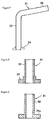
Figure 7 shows an FRP curved support 31 relating to an
embodiment of the present invention. FRP curved support 31
has a support portion 32 and an arm portion 33 which curves
from the upper end of said support portion 32 and extends at
an angle. This support portion 32 and arm portion 33 are
integrally moulded.
The structure of the FRP curved support 31 relating to the
present invention is complete as it is but, in practice, it
is most often employed fitted to a base or the like and so,
as shown by the two sets of dotted lines in Figure 7, at the
end of support portion 32 on the other side from the arm
portion, that is to say at the bottom end of support portion
32 in this embodiment, it is preferred that there be provided
a flange member 34 used for fitting and securing to a base or
the like.
With regard to this flange member 34, as shown in Figure 8
for example, said flange member 34 can be separately formed
from the support portion 32 and this flange member 34 then
joined to support portion 32 by adhesion or fastening. In
the case of a flange member 34 of separate structure, there
may be used for example a separately moulded FRP product or a
durable metal such as stainless steel, and depending on the
circumstances there can also be formed a hybrid structure of
FRP and metal.
Again, the flange member can also be integrally moulded with
the support portion 32. For example, as shown in Figure 9, a
flange 34a comprising FRP can be integrally moulded with the
support portion 32 at the bottom end of said support portion
32. In such circumstances, joining together by adhesion or
fastening is unnecessary and, furthermore, being an FRP
moulded body connected to support portion 32, it is possible
to ensure sufficient strength and rigidity in flange portion
34a.
Even where the length of such an FRP curved support 31 is 3 m
or above, production can be carried out easily and cheaply by
the production method described below. FRP curved support 31
is extremely light compared to a conventional such item made
of metal, and even at a length of 3 m or above it has
outstanding handling characteristics, so large-size heavy
machinery or the like is not required at the time of
employment. Furthermore, since the support as a whole is
considerably reduced in weight, the load on the base or the
like is also reduced, so the strength required of the base or
the like is also lowered.
With regard to the support itself too, sufficiently high
strength and rigidity can be ensured by suitable choice of
the type of reinforcing fibre, the percentage impregnation
and the type of resin, etc, in accordance with the usage
objectives. Furthermore, being light, there is very little
deflection under its own weight, and it is possible to
produce long supports easily. Moreover, being made of FRP,
there is fundamentally no problem of rusting. In addition,
when compared to a metal-made item, the impact absorption
capacity is excellent and it behaves advantageously in terms
of motor vehicle impact and the like.
An FRP curved support 31 with the aforesaid outstanding
characteristics can typically be produced easily and cheaply
by either of the aforesaid two methods of production relating
to the present invention. The flange member may be
separately moulded and then connected to the support portion
of the moulded FRP curved support, or the shape of the mould
may be made to include a flange member, which is integrally
moulded with the aforesaid support portion. An FRP curved
support of specified shape can readily be integrally moulded
by either of the aforesaid methods and, even when of long
length, production can be carried out simply and cheaply.
The applications of the FRP curved support relating to the
present invention are not particularly restricted, but to
provide some examples it is suitable as a garage support, a
support for signboards such as advertisements and road signs,
a support to hold up a roof such as in the case of a petrol
station/gasoline stand, or as a support for a veranda or for
a canopy.
Figure 10 shows a cross-section of the tubular portion of an
FRP tubular body 41 relating to another embodiment of the
present invention. Tubular portion 42 of this FRP tubular
body 41 has an external diameter of at least 3 m, and it is
constructed as a connected body of components 43 based on
division into two or more parts (in the example in the figure
there are four) in the circumferential direction. Each
divided component 43 is moulded as a circular-arc shaped
component, and mutually adjacent such divided components 43
are integrally coupled via connecting members 44 interposed
between them.
The opposing end faces of adjacent divided components 43 are
moulded with stepped regions 45 of projecting/recessed shape,
and both end faces of the connecting members 44 are also
moulded with stepped regions 46 of projecting/recessed shape,
so that the stepped region 45 on the divided component 43
side and the stepped region on the connecting member 44 side
mutually fit together. After fitting the connecting members
44, they are secured by adhesion or the like, so that there
is integral connection between divided component 43,
connecting member 44 and divided component 43 continuously in
the circumferential direction.
Connecting members 44 are separately moulded from the divided
components 43 and, while they may be composed of metal or
other such material, in order to maintain the lightness of
the tubular body as a whole, and again in order to ensure
good connection with the divided components 43, it is
preferred that they comprise the same FRP as said divided
components 43.
Constructions other than as described above can also be
utilized for the integral coupling of the divided components.
For example, as shown in Figure 11 recesses 55 can be formed
at the opposing end faces 54 of mutually adjacent divided
components 53, then a flat connecting member 50 fitted in
each recess 55 and connection effected with opposing end
faces 54 butting.
Again, as shown in Figure 12, the opposing faces 64 of
mutually adjacent divided components 63 may be given
projecting/recessed forms which mutually fit together, and
construction effected by directly joining together the end
faces 64 without an interposed connecting member.
Moreover, while the divided components themselves can be
given a single sheet structure of FRP, a sandwich structure
with a core material arranged between FRP skin sheets is more
preferred in terms of satisfying all the requirements of
lightness, strength and rigidity.
For example, as shown in Figure 13, a divided component 73 is
preferred which has a sandwich structure in which FRP skin
sheets 72a and 72b are arranged at the two faces of a core
material 71. In such a sandwich structure, where required,
it is possible to provide ribs 74 at suitable positions at a
suitable spacing. By means of ribs 74, as well as it being
possible to further'enhance the strength and rigidity, the
shape retentivity is also improved. The material for ribs 74
may be wood or metal but, taking into account integral
mouldability to FRP skin sheets 72a and 72b, it is again
preferred that they comprise FRP. As the material for core
material 71 there can be used wood or a foam, but from the
point of view of lightness a foam of low specific gravity is
preferred. In particular, by using such a core material 71
it is possible to enhance the thermal insulation properties.
With regard to the shape of the tubular portion of the FRP
tubular body relating to the present invention, providing it
constitutes a tubular body any shape thereof can be employed.
As well as the circular tubular shape of the kind shown in
aforesaid Figure 10, there can be employed structures such as
the circular conical frustum-shaped tubular portion 81 shown
in Figure 14, the circular conical frustum-shaped tubular
portion 82 where the generatrix curves as shown in Figure 15,
the tubular portion 83 of quadrangular cross-section shown in
Figure 16, the tubular portion 84 of hexagonal cross-section
shown in Figure 17 and the tubular portion 85 of octagonal
cross-section shown in Figure 18.
Furthermore the shape of each divided component can also be
freely changed in accordance with the particular shape of the
tubular portion as described above. In contrast to the
divided components 43 shown in Figure 10 which comprise
circular arc-shaped members of substantially fixed cross-sectional
shape, in the case for example of the tubular
portions 81 and 82 shown in Figure 14 and Figure 15, the
divided members thereof while still be circular arc shaped
will vary continuously in their cross-sectional shape. Again,
in the case of tubular portions 83, 84 and 85 shown in
Figures 16 to 18, each divided component can be formed as a
single flat-sheet shape or can be formed as an L-shaped or U-shaped
panel member.
In this way, in the case where the components from which the
tubular portion is constructed comprise a plurality of
members by division in the circumferential direction, each
divided component can be made small and moulding is simple,
so it is possible in practice to produce a large-size FRP
tubular body 41 of external diameter 3 m or more, easily and
cheaply.
Furthermore, by employing a joint structure between divided
components as shown in Figures 10 to 12, connection and
assembly on site becomes possible.
Moreover, even where the tubular body as a whole is large,
since each divided component can be moulded to a small size,
there are essentially no restrictions in terms of moulding on
the shapes of the divided components themselves, and it
becomes possible to freely and easily produce tubular bodies
of various shapes as shown in Figures 14 to 18, and a
broadening of applications can be achieved.
As the reinforcing fibre of the FRP layer in the aforesaid
FRP tubular bodies, it is preferred that there be used carbon
fibre unidirectional material, woven material, mat or strands,
or glass fibre unidirectional material, woven material, mat
or roving, either on their own or in the form of mixtures.
In particular, in order to achieve maximum effect in terms of
weight reduction, the use of carbon fibre is preferred.
Furthermore, with regard to the carbon fibre, rather than the
carbon fibre yarn normally containing less than 10,000
filaments, the use of a carbon fibre filament tow where the
number of filaments lies in the range 10,000 to 300,000, and
preferably 50,000 to 150,000, is more outstanding in terms of
the resin impregnation, the handling of the reinforcing fibre
substrate and also the cost of the reinforcing fibre
substrate, so this is preferred. Again, where a carbon fibre
woven material is arranged at the surface of the FRP tubular
body, there is enhanced surface design potential, so this is
further preferred. Again, where required, or in accordance
with the mechanical properties demanded, the reinforcing
fibre substrate may be formed by superimposing a number of
reinforcing fibre layers, and this reinforcing fibre
substrate employed for resin impregnation. As the
superimposed reinforcing fibre layers, there can be suitably
superimposed layers of unidirectionally arranged carbon fibre
or woven material layers, and the fibre orientation direction
can be appropriately selected in accordance with the required
strength direction.
It is preferred, in terms of the moulding characteristics and
cost, that the FRP resin be a thermosetting resin such as an
epoxy, unsaturated polyester, phenolic or vinyl ester resin.
However, it is also possible to use thermoplastic resins such
as nylon and ABS resin, or mixtures of thermosetting resin
and thermoplastic resin.
As the core material, there can be used foam, wood or the
like, but from the point of view of weight reduction a foam
is preferred. As the foam material, there may be used
polyurethane, polystyrene, polyethylene, polypropylene,
polyimide, PVC, silicone or the like, and it is preferred
that the specific gravity of the foam be selected from within
the range 0.02 to 0.2. The type and specific gravity of the
core material can be selected according to the properties
demanded of the FRP tubular body and the type of resin used,
etc. If the specific gravity is less than 0.02, there is a
fear that sufficient strength will not be obtained. On the
other hand, if the specific gravity exceeds 0.2 then, while
the strength is raised, the weight is also increased and this
goes against the objective of weight reduction.
Examples of applications of the FRP tubular body relating to
the present invention include large-size tanks, waste gas
ducts (chimneys, ducts for discharged gases within high-speed
road tunnels, and the like), cooling tower containers, silos,
water channel shutters, broadcasting masts, towers, revolving
tubes in parks, and lamp posts, etc.
Industrial Applicability
As explained above, in accordance with the FRP tubular body
of the present invention and method of manufacture thereof,
there are no substantial restrictions in terms of length and
diameter, and long large-diameter FRP tubular bodies can be
moulded easily and cheaply. Again, since no special moulding
equipment is required, from this aspect too it is possible to
produce the desired FRP tubular bodies easily and cheaply.
In addition, the FRP curved support of the present invention
is light and easy to handle, does not require large heavy
machinery or the like at the time of employment, permits the
strength of the base to be lowered, and essentially shows no
problem of rust generation. Furthermore, there is little
deflection under its own weight and the length of the arm
portion can readily be increased. Moreover, it can show an
outstanding impact absorbing capacity in terms of motor
vehicle impact and the like. Thus, it is possible to obtain
a support with extremely outstanding properties not found
with conventional metal-made items.
In addition, where the tubular portion is composed of a
plurality of components by division in the circumferential
direction, the moulding of each such divided component is
easy and it becomes possible to produce large-size FRP
tubular bodies of size 3 m and above, and even 10 m or above,
both easily and cheaply. Again, large size moulds are
unnecessary and, from this aspect too, production can be
simplified and production costs lowered. Furthermore, by
employing a joint construction for the divided components as
shown in Figures 10 to 12, it becomes possible to carry out
connection and assembly easily on site. Moreover, since each
divided component is small, transportation is both cheap and
easy.