EP1169236B1 - Composite container closure - Google Patents
Composite container closure Download PDFInfo
- Publication number
- EP1169236B1 EP1169236B1 EP00911896A EP00911896A EP1169236B1 EP 1169236 B1 EP1169236 B1 EP 1169236B1 EP 00911896 A EP00911896 A EP 00911896A EP 00911896 A EP00911896 A EP 00911896A EP 1169236 B1 EP1169236 B1 EP 1169236B1
- Authority
- EP
- European Patent Office
- Prior art keywords
- panel
- rim
- side panel
- dependent
- closure member
- Prior art date
- Legal status (The legal status is an assumption and is not a legal conclusion. Google has not performed a legal analysis and makes no representation as to the accuracy of the status listed.)
- Expired - Lifetime
Links
- 239000002131 composite material Substances 0.000 title claims description 18
- 239000000463 material Substances 0.000 claims abstract description 27
- 239000011087 paperboard Substances 0.000 claims abstract description 14
- 230000001419 dependent effect Effects 0.000 claims description 50
- 239000004033 plastic Substances 0.000 claims description 23
- 230000002093 peripheral effect Effects 0.000 claims description 15
- 238000002347 injection Methods 0.000 claims description 12
- 239000007924 injection Substances 0.000 claims description 12
- 239000012815 thermoplastic material Substances 0.000 claims description 5
- 239000011324 bead Substances 0.000 claims description 2
- 238000001746 injection moulding Methods 0.000 abstract description 10
- 229920001169 thermoplastic Polymers 0.000 description 12
- 239000004416 thermosoftening plastic Substances 0.000 description 12
- 238000000034 method Methods 0.000 description 7
- 239000002991 molded plastic Substances 0.000 description 7
- 238000000465 moulding Methods 0.000 description 7
- 238000013459 approach Methods 0.000 description 4
- 238000004519 manufacturing process Methods 0.000 description 3
- 239000000088 plastic resin Substances 0.000 description 3
- 238000013461 design Methods 0.000 description 2
- 239000000123 paper Substances 0.000 description 2
- 238000001816 cooling Methods 0.000 description 1
- 230000009977 dual effect Effects 0.000 description 1
- 238000003780 insertion Methods 0.000 description 1
- 230000037431 insertion Effects 0.000 description 1
- 238000012986 modification Methods 0.000 description 1
- 230000004048 modification Effects 0.000 description 1
- 238000012856 packing Methods 0.000 description 1
- 238000012552 review Methods 0.000 description 1
- 230000006641 stabilisation Effects 0.000 description 1
- 238000011105 stabilization Methods 0.000 description 1
- 239000000758 substrate Substances 0.000 description 1
Images
Classifications
-
- B—PERFORMING OPERATIONS; TRANSPORTING
- B65—CONVEYING; PACKING; STORING; HANDLING THIN OR FILAMENTARY MATERIAL
- B65D—CONTAINERS FOR STORAGE OR TRANSPORT OF ARTICLES OR MATERIALS, e.g. BAGS, BARRELS, BOTTLES, BOXES, CANS, CARTONS, CRATES, DRUMS, JARS, TANKS, HOPPERS, FORWARDING CONTAINERS; ACCESSORIES, CLOSURES, OR FITTINGS THEREFOR; PACKAGING ELEMENTS; PACKAGES
- B65D77/00—Packages formed by enclosing articles or materials in preformed containers, e.g. boxes, cartons, sacks or bags
- B65D77/10—Container closures formed after filling
- B65D77/20—Container closures formed after filling by applying separate lids or covers, i.e. flexible membrane or foil-like covers
-
- B—PERFORMING OPERATIONS; TRANSPORTING
- B65—CONVEYING; PACKING; STORING; HANDLING THIN OR FILAMENTARY MATERIAL
- B65D—CONTAINERS FOR STORAGE OR TRANSPORT OF ARTICLES OR MATERIALS, e.g. BAGS, BARRELS, BOTTLES, BOXES, CANS, CARTONS, CRATES, DRUMS, JARS, TANKS, HOPPERS, FORWARDING CONTAINERS; ACCESSORIES, CLOSURES, OR FITTINGS THEREFOR; PACKAGING ELEMENTS; PACKAGES
- B65D43/00—Lids or covers for rigid or semi-rigid containers
-
- B—PERFORMING OPERATIONS; TRANSPORTING
- B65—CONVEYING; PACKING; STORING; HANDLING THIN OR FILAMENTARY MATERIAL
- B65D—CONTAINERS FOR STORAGE OR TRANSPORT OF ARTICLES OR MATERIALS, e.g. BAGS, BARRELS, BOTTLES, BOXES, CANS, CARTONS, CRATES, DRUMS, JARS, TANKS, HOPPERS, FORWARDING CONTAINERS; ACCESSORIES, CLOSURES, OR FITTINGS THEREFOR; PACKAGING ELEMENTS; PACKAGES
- B65D5/00—Rigid or semi-rigid containers of polygonal cross-section, e.g. boxes, cartons or trays, formed by folding or erecting one or more blanks made of paper
- B65D5/42—Details of containers or of foldable or erectable container blanks
- B65D5/64—Lids
Definitions
- This invention relates generally to closure arrangements, and more particularly it relates to a closure arrangement including a composite lid composed of a molded plastic rim and a central panel of paperboard or similar material which includes an extension of the central panel which is positioned outside of the plastic rim providing a surface which may be printed upon.
- the present invention is drawn to a lid or cover for a container of the type where it snaps over an upper flange or edge of the container.
- Covers of the type described herein typically utilize injection molding to provide the necessary plastic rims or edges for the closure.
- a sheet of printed material such as paperboard
- molding a plastic resin bonded to the panel compatible with the panel material to form the rim or engagement means is common practice.
- the wings or flaps are attached to the panel in the usual manner, whereby the molded plastic folds over the top surface of the flap resulting in the flap being contained from the outside, thus only being visible from the underside.
- the present invention provides a composite container closure member as defined in claim 1 in which the features in the preamble part of the claim are known from US-A-3956550 discussed previously.
- the present invention is directed to improvements in the production of composite container closures which comprise a flexible blank, such as paperboard or other material which is easily printed upon with a molded rim defining a connecting portion which is molded in contact with the blank.
- the invention relates to such products in which a blank panel is surrounded by a peripheral element, such as a rim or connecting device.
- Such products typically include lids or similar covers.
- the top blank or panel is clamped in a planar position in a mold cavity which includes a peripheral channel for receiving synthetic injection molded thermal plastic material to connect the rim around the panel.
- a composite lid including a blank of sheet material and a peripheral molding wherein a marginal portion of the blank is displaced out of the general lateral plane of the central panel thereof and the peripheral molding includes a portion of the outer marginal portion bonded to a portion of the marginal portion of the blank.
- the main panel can have a number of flaps or wings folded from it and the folding does not necessarily require a change in plane.
- the wings or extended portions of the upper panel control shrinkage and keep the lid from distorting.
- having the wing or peripheral panel portion extended outside of the plastic rim the ability is provided therein to have a printed surface on the lid skirt.
- a composite article or lid including a blank of sheet material and a peripheral molding, wherein a marginal portion of the blank is displaced out of the general plane of the central panel, and the peripheral molding includes the marginal portion of the blank bonded to a portion of the rim on an exterior surface, to control longitudinal shrinkage and provide a printed surface on such marginal section.
- the object of the invention is to construct the fold line on the central panel or paper insert in such a manner that the insert when folded in a mold provides the top surface of the main panel and the bottom surface of any peripheral panel to the flowing plastic.
- This arrangement is accomplished by the placement of an offset cut in the fold line that occurs between the upper or insert panel and the dependent side panels.
- a number of different methods for providing access to the placement of the plastic so that it has contact to the top surface of the panel and to the inside surfaces of the dependent side panels or wings can be achieved by means of cuts or partial cuts between the two panels or also simple openings for plastic injection points at the juncture point of the planar top panel and the dependent side panels.
- closure design of the present invention provides substantial advantages over the prior art and that it provides in addition to shrinkage or wrinkling stabilization, exterior as well as top printed surfaces, and easily facilitates the production of the closure of the present invention by means of employing injection molding of thermal plastic material.
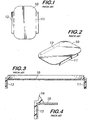
- FIG. 1 is a plan view of the paperboard top panel 10 with peripheral or dependent side panels 11 and 12.
- the main or top planar panel 10 carries a printed surface.
- the dependent or side panels are folded down as seen in FIG. 2.
- a molded edge or skirt has been applied to the lid as seen in the sectional view shown in FIG. 3, wherein the plastic lays upon the outer edges of the main panel 10 and on the outsides of dependent or side panels 11 and 12.
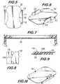
- FIG. 5 an upper or plan view of the paperboard portion of the lid in accordance with the teachings of the present invention is shown.
- the side panels are folded, for example, utilizing dependent or side panel 11 is folded along the lines 13 and 14 and with an actual cut being made as shown at cut 15 where the cut is slightly inserted into the main part of panel 10.
- the manner in which the side panels are dependent in the folded position is seen in FIG. 6.
- top panel 10 is provided with a projection extension 10A which will overlay the injection molded plastic which is initially injected at point 16 which has been folded in a downward direction to provide the necessary folded rim.
- Much of the downward projecting panel 12 will be behind the plastic with peripheral portion 10A extending on the outside of the molded rim.
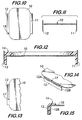
- FIG. 10 Another approach, described in FIG. 10, provides initially with the top horizontal panel 10 connected at corner nicks 18 to dependent side panels 11 and 12.
- the paperboard panel consisting of 10, 11 and 12 is then folded with the dependent side panels placed in a downward direction and the nicks sheared as in FIG. 11 so that when thermoplastic is injection molded, as shown in FIG. 12, the plastic rim will be formed to secure the upper portion of planar panel 10 and then lie behind dependent panels 11 and 12, as seen in FIG. 12.
- FIGS. 13, 14, and 15 show yet another variation wherein a cut 17 is provided partially through between the dependent side panel, such as 12, and the horizontal planar panel 10 as defined by 17 in FIG. 13.
- Side panel 12 has oppositely disposed end portions 12A and 12B which remain attached to top panel 10.
- Side panel 11 is similarly configured.
- the paperboard is then inserted around a curved core in the mold providing an opening 17 which is stretched out as seen in FIG. 14, after which injection of the thermoplastic occurs at point 16, as shown in FIG. 15, and a rim is formed adjacent the outside edge of top panel 10 and behind the dependent side panels, such as 11 (not shown) or 12, but in front of end portions 12A and 12B as seen in FIG. 15.
- peripheral, or side panels are on the outside of the thermoplastic which has been added by injection molding, providing for multiple printed surfaces on the exterior of the rim.
Landscapes
- Engineering & Computer Science (AREA)
- Mechanical Engineering (AREA)
- Injection Moulding Of Plastics Or The Like (AREA)
- Closures For Containers (AREA)
- Glass Compositions (AREA)
- Cartons (AREA)
Abstract
Description
Claims (9)
- A composite container closure member comprising:characterised in thata continuous rim formed from an injection moulded thermoplastic material;a skirt depending from the rim for engagement with the wall of a container body;a central top panel (10) formed from a blank of generally flexible sheet material;at least one peripheral dependent side panel (11, 12) formed from the same blank as the central top panel (10), initially joined to the central top panel (10);whereby the dependent side panel (11, 12) is positioned vertically in a plane perpendicular to the central top panel (10) thereby having an interior side and an exterior side;the central panel (10) is disposed within the rim and bonded thereto by the material of the rim;and the rim material is further bonded to the dependent side panel (11, 12)
the rim material is bonded to the interior side of the dependent side panel (11, 12) whereby at least a portion of said side panel (11, 12) is bonded to an exterior portion of the rim material such that the exterior side of the dependent side panel (11,12) provides a printable surface on the exterior of the rim. - A composite container closure member as claimed in claim 1 characterised in that the blank further includes a cut (15) partially separating the dependent side panel (11, 12) from the central top panel (10).
- A composite container closure member as claimed in claim 2 characterised in that the partially separated dependent side panel (11, 12) is further completely separated from the central top panel (10).
- A composite container closure member as claimed in any of the preceding claims characterised in that the dependent side panel (11, 12) is folded at a junction (14) between the central top panel (10) and the dependent side panel (11, 12) to position the dependent side panel (11, 12) in a plane perpendicular to the central top panel (10).
- A composite container closure member as claimed in any of the preceding claims characterised in that only a portion of the dependent side panel (11, 12) extends over and is bonded to the rim.
- A composite container closure member as claimed in any of the preceding claims characterised in that the thermoplastic material is injected at a location (16) at the joinder of the dependent side panel (11, 12) to the central top panel (10).
- A composite container closure member as claimed in any of the preceding claims characterised in that the plastic at the point of injection (16) forms a bead adapted to facilitate stacking of the closure member.
- A composite container closure member as claimed in any of the preceding claims characterised in that the dependent side panel (11, 12) is deformed prior to injection of the thermoplastic material to facilitate the flow of the material behind the dependent side panel (11, 12).
- A composite container closure member as claimed in any of the preceding claims characterised in that the flexible sheet material of the blank is paperboard.
Applications Claiming Priority (3)
| Application Number | Priority Date | Filing Date | Title |
|---|---|---|---|
| US253305 | 1999-02-19 | ||
| US09/253,305 US6053353A (en) | 1999-02-19 | 1999-02-19 | Composite container closure |
| PCT/US2000/004423 WO2000071434A1 (en) | 1999-02-19 | 2000-02-22 | Composite container closure |
Publications (3)
| Publication Number | Publication Date |
|---|---|
| EP1169236A1 EP1169236A1 (en) | 2002-01-09 |
| EP1169236A4 EP1169236A4 (en) | 2003-08-13 |
| EP1169236B1 true EP1169236B1 (en) | 2005-07-27 |
Family
ID=22959717
Family Applications (1)
| Application Number | Title | Priority Date | Filing Date |
|---|---|---|---|
| EP00911896A Expired - Lifetime EP1169236B1 (en) | 1999-02-19 | 2000-02-22 | Composite container closure |
Country Status (6)
| Country | Link |
|---|---|
| US (1) | US6053353A (en) |
| EP (1) | EP1169236B1 (en) |
| AT (1) | ATE300481T1 (en) |
| AU (1) | AU3371700A (en) |
| DE (1) | DE60021546D1 (en) |
| WO (1) | WO2000071434A1 (en) |
Families Citing this family (35)
| Publication number | Priority date | Publication date | Assignee | Title |
|---|---|---|---|---|
| US6196451B1 (en) * | 1999-10-13 | 2001-03-06 | Double “H” Plastics, Inc. | Paper-sided composite lid |
| AU4717801A (en) * | 1999-12-14 | 2001-06-25 | Double "H" Plastics, Inc. | Stackable hinged container lid having detents |
| WO2002057154A1 (en) * | 2001-01-16 | 2002-07-25 | Ajava Pinata, Llc | Suspended containers |
| WO2002094664A1 (en) * | 2001-05-18 | 2002-11-28 | Stanpac Inc. | Tamper resistant composite lids for food containers |
| US7086545B2 (en) | 2002-01-16 | 2006-08-08 | Ajava Pinata, L.L.C. | Suspended containers |
| AU2003234509A1 (en) * | 2002-05-06 | 2003-11-17 | Ajava Pinata, Llc | Suspended containers |
| US6824916B2 (en) * | 2002-05-16 | 2004-11-30 | Motorola, Inc. | Hybrid battery housing |
| US20050115965A1 (en) * | 2003-10-28 | 2005-06-02 | Double "H" Plastics, Inc. | Composite container closure with detachable utensil |
| US7597213B2 (en) * | 2004-12-22 | 2009-10-06 | Kimberly-Clark Worldwide, Inc. | Container caps and containers |
| DK1855956T3 (en) | 2005-02-28 | 2011-05-30 | Stanpac Inc | Compound closures for containers |
| USD530223S1 (en) | 2005-03-01 | 2006-10-17 | Kimberly-Clark Worldwide, Inc. | Tissue dispenser |
| US20070210092A1 (en) * | 2006-03-10 | 2007-09-13 | Ivonis Mazzarolo | Paper food container with injection molded top rim structure and method of manufacturing same |
| US7520404B2 (en) * | 2006-03-10 | 2009-04-21 | Ivonis Mazzarolo | Paper food container with injection molded top rim structure and method of manufacturing same |
| US20080099546A1 (en) * | 2006-10-27 | 2008-05-01 | J.L. Clark, Inc. | Container and closure for a container |
| USD565946S1 (en) | 2006-10-27 | 2008-04-08 | J.L. Clark, Inc. | Closure for a carton |
| WO2009047725A1 (en) | 2007-10-09 | 2009-04-16 | The Folgers Coffee Company | Visual vacuum indicator |
| WO2010039720A1 (en) * | 2008-09-30 | 2010-04-08 | Berry Plastics Corporation | Microwavable food package |
| BRPI1008943A2 (en) * | 2009-03-13 | 2016-03-15 | Nestec Sa | composite container covers |
| US20100237068A1 (en) * | 2009-03-17 | 2010-09-23 | Rubbermaid Incorporated | Container With In-Molded Exposed Panel |
| US8308021B2 (en) | 2010-08-12 | 2012-11-13 | S.C. Johnson & Son, Inc. | Disposable storage container |
| US9469445B2 (en) | 2011-02-07 | 2016-10-18 | Berry Plastics Corporation | Package with lid sealing system |
| US8998030B2 (en) | 2011-02-07 | 2015-04-07 | Berry Plastics Corporation | Package with lid sealing system |
| US8991632B2 (en) | 2011-07-07 | 2015-03-31 | Berry Plastics Corporation | Canister |
| US9032698B2 (en) | 2011-07-07 | 2015-05-19 | Berry Plastics Corporation | Package with lid sealing system |
| USD700906S1 (en) * | 2011-08-08 | 2014-03-11 | Htc Corporation | Case |
| MX2015015310A (en) * | 2013-05-03 | 2016-08-23 | Berry Plastics Corp | Container closure. |
| US9630762B2 (en) | 2014-01-22 | 2017-04-25 | Berry Plastics Corporation | Package with peelable closure |
| WO2016014825A1 (en) | 2014-07-23 | 2016-01-28 | Berry Plastics Corporation | Package with peelable closure |
| AU2014408671B2 (en) * | 2014-10-07 | 2017-11-02 | Stanpac Inc. | Tamper evident lid and method of making same |
| USD953857S1 (en) * | 2020-04-20 | 2022-06-07 | Comcast Cable Communications, Llc | Capsule |
| USD957249S1 (en) * | 2020-04-20 | 2022-07-12 | Comcast Cable Communications, Llc | Capsule |
| USD957248S1 (en) * | 2020-04-20 | 2022-07-12 | Comcast Cable Communications, Llc | Capsule |
| USD943411S1 (en) * | 2020-04-20 | 2022-02-15 | Comcast Cable Communications, Llc | Capsule |
| USD944082S1 (en) * | 2020-04-20 | 2022-02-22 | Comcast Cable Communications, Llc | Capsule |
| USD953856S1 (en) * | 2020-04-20 | 2022-06-07 | Comcast Cable Communications, Llc | Capsule |
Family Cites Families (18)
| Publication number | Priority date | Publication date | Assignee | Title |
|---|---|---|---|---|
| US3458619A (en) * | 1965-04-13 | 1969-07-29 | Anger Kunststoff | Process for producing molded bodies |
| US3360152A (en) * | 1965-08-27 | 1967-12-26 | Robert S Leers | Plastic housings |
| US3412889A (en) * | 1967-11-24 | 1968-11-26 | Dow Chemical Co | Container for dairy products or the like |
| US3705831A (en) * | 1971-07-09 | 1972-12-12 | Gen Motors Corp | Method of fabricating an insulated storage bin |
| GB1450529A (en) * | 1972-11-01 | 1976-09-22 | Airfix Ind Ltd | Production of composite closures |
| US3910483A (en) * | 1974-11-07 | 1975-10-07 | Int Paper Co | Two-piece, paperboard container construction |
| US4038359A (en) * | 1975-01-27 | 1977-07-26 | Garlock Inc. | Method of making a shaft seal with dual lip |
| US4301941A (en) * | 1978-04-07 | 1981-11-24 | Phillips Petroleum Company | Container closure |
| CH630308A5 (en) * | 1978-07-25 | 1982-06-15 | Obrist Ag Albert | CONTAINER WITH LID IN PLASTIC MATERIAL. |
| US4228912A (en) * | 1978-12-11 | 1980-10-21 | Eps (Research And Development) Limited | Container |
| US4238047A (en) * | 1979-10-04 | 1980-12-09 | Container Corporation Of America | Composite closure member |
| US4585145A (en) * | 1982-02-17 | 1986-04-29 | Pitroda Pravin G | Tape dispenser |
| US4438864A (en) * | 1982-06-09 | 1984-03-27 | Container Corporation Of America | Tamperproof closure |
| US4448345A (en) * | 1982-07-29 | 1984-05-15 | Container Corporation Of America | Composite lid |
| US4442971A (en) * | 1982-09-13 | 1984-04-17 | Container Corporation Of America | Peelable, sealable closure arrangement |
| SE8804229L (en) * | 1988-11-23 | 1990-05-24 | Akerlund & Rausing Licens Ab | AEROUS CLOSING DEVICE FOR PLANT CUT OFF PACKAGING |
| CH679147A5 (en) * | 1989-06-07 | 1991-12-31 | Tetra Pak Romont | |
| US5197935A (en) * | 1989-11-13 | 1993-03-30 | Tetra Alpha Holdings S.A. | Package for flowable contents with an externally smoothly constructed sealing seam, a method of producing such a package and an apparatus for carrying out the method |
-
1999
- 1999-02-19 US US09/253,305 patent/US6053353A/en not_active Expired - Lifetime
-
2000
- 2000-02-22 DE DE60021546T patent/DE60021546D1/en not_active Expired - Lifetime
- 2000-02-22 EP EP00911896A patent/EP1169236B1/en not_active Expired - Lifetime
- 2000-02-22 WO PCT/US2000/004423 patent/WO2000071434A1/en not_active Ceased
- 2000-02-22 AT AT00911896T patent/ATE300481T1/en not_active IP Right Cessation
- 2000-02-22 AU AU33717/00A patent/AU3371700A/en not_active Abandoned
Also Published As
| Publication number | Publication date |
|---|---|
| ATE300481T1 (en) | 2005-08-15 |
| WO2000071434A1 (en) | 2000-11-30 |
| US6053353A (en) | 2000-04-25 |
| AU3371700A (en) | 2000-12-12 |
| EP1169236A4 (en) | 2003-08-13 |
| DE60021546D1 (en) | 2005-09-01 |
| EP1169236A1 (en) | 2002-01-09 |
Similar Documents
| Publication | Publication Date | Title |
|---|---|---|
| US6053353A (en) | Composite container closure | |
| US4620665A (en) | Container with integral toggle closure | |
| US6196451B1 (en) | Paper-sided composite lid | |
| US4407410A (en) | Book type cassette holder and method of making same | |
| US8292111B2 (en) | Tamper evident plastic dispensing container | |
| US7703626B2 (en) | Composite closures for containers | |
| US20210107707A1 (en) | Novel tamper evident containers | |
| US7845519B2 (en) | Tamper evident plastic dispensing container | |
| US12110155B2 (en) | Tamper evident container | |
| US20120031903A1 (en) | Removable Lid for a Container | |
| US20020020641A1 (en) | Box or a box element formed of a plastic material | |
| US4838432A (en) | Carton and blank for packaging ice cream and the like | |
| US20210229876A1 (en) | Tamper evident container | |
| US20060000879A1 (en) | Case comprising a rigid face and a flexible face able to be closed and maintained in the closed state | |
| JPH10119965A (en) | Box with lid | |
| EP0639141A1 (en) | Packaging container and method of producing the same | |
| US6098329A (en) | Tag protector | |
| JP2593374Y2 (en) | Packaging containers | |
| JP2598319Y2 (en) | Cup-shaped container | |
| JPH072429Y2 (en) | Molded product for heat shrinkable lid | |
| JPH01254563A (en) | Lid for sealing container | |
| JPH0647126U (en) | Packaging box | |
| JPH0444963A (en) | Sealing lid | |
| AU742370B2 (en) | Lids and containers with lids | |
| JP2566843Y2 (en) | Liquid container closure cover |
Legal Events
| Date | Code | Title | Description |
|---|---|---|---|
| PUAI | Public reference made under article 153(3) epc to a published international application that has entered the european phase |
Free format text: ORIGINAL CODE: 0009012 |
|
| 17P | Request for examination filed |
Effective date: 20010818 |
|
| AK | Designated contracting states |
Kind code of ref document: A1 Designated state(s): AT BE CH CY DE DK ES FI FR GB GR IE IT LI LU MC NL PT SE |
|
| A4 | Supplementary search report drawn up and despatched |
Effective date: 20030703 |
|
| RIC1 | Information provided on ipc code assigned before grant |
Ipc: 7B 65D 43/08 A Ipc: 7B 65D 43/02 B |
|
| 17Q | First examination report despatched |
Effective date: 20040707 |
|
| GRAP | Despatch of communication of intention to grant a patent |
Free format text: ORIGINAL CODE: EPIDOSNIGR1 |
|
| GRAS | Grant fee paid |
Free format text: ORIGINAL CODE: EPIDOSNIGR3 |
|
| GRAA | (expected) grant |
Free format text: ORIGINAL CODE: 0009210 |
|
| AK | Designated contracting states |
Kind code of ref document: B1 Designated state(s): AT BE CH CY DE DK ES FI FR GB GR IE IT LI LU MC NL PT SE |
|
| PG25 | Lapsed in a contracting state [announced via postgrant information from national office to epo] |
Ref country code: IT Free format text: LAPSE BECAUSE OF FAILURE TO SUBMIT A TRANSLATION OF THE DESCRIPTION OR TO PAY THE FEE WITHIN THE PRESCRIBED TIME-LIMIT;WARNING: LAPSES OF ITALIAN PATENTS WITH EFFECTIVE DATE BEFORE 2007 MAY HAVE OCCURRED AT ANY TIME BEFORE 2007. THE CORRECT EFFECTIVE DATE MAY BE DIFFERENT FROM THE ONE RECORDED. Effective date: 20050727 Ref country code: CH Free format text: LAPSE BECAUSE OF FAILURE TO SUBMIT A TRANSLATION OF THE DESCRIPTION OR TO PAY THE FEE WITHIN THE PRESCRIBED TIME-LIMIT Effective date: 20050727 Ref country code: LI Free format text: LAPSE BECAUSE OF FAILURE TO SUBMIT A TRANSLATION OF THE DESCRIPTION OR TO PAY THE FEE WITHIN THE PRESCRIBED TIME-LIMIT Effective date: 20050727 Ref country code: AT Free format text: LAPSE BECAUSE OF FAILURE TO SUBMIT A TRANSLATION OF THE DESCRIPTION OR TO PAY THE FEE WITHIN THE PRESCRIBED TIME-LIMIT Effective date: 20050727 Ref country code: NL Free format text: LAPSE BECAUSE OF FAILURE TO SUBMIT A TRANSLATION OF THE DESCRIPTION OR TO PAY THE FEE WITHIN THE PRESCRIBED TIME-LIMIT Effective date: 20050727 Ref country code: BE Free format text: LAPSE BECAUSE OF FAILURE TO SUBMIT A TRANSLATION OF THE DESCRIPTION OR TO PAY THE FEE WITHIN THE PRESCRIBED TIME-LIMIT Effective date: 20050727 Ref country code: FI Free format text: LAPSE BECAUSE OF FAILURE TO SUBMIT A TRANSLATION OF THE DESCRIPTION OR TO PAY THE FEE WITHIN THE PRESCRIBED TIME-LIMIT Effective date: 20050727 |
|
| REG | Reference to a national code |
Ref country code: GB Ref legal event code: FG4D |
|
| REG | Reference to a national code |
Ref country code: CH Ref legal event code: EP |
|
| REG | Reference to a national code |
Ref country code: IE Ref legal event code: FG4D |
|
| REF | Corresponds to: |
Ref document number: 60021546 Country of ref document: DE Date of ref document: 20050901 Kind code of ref document: P |
|
| PG25 | Lapsed in a contracting state [announced via postgrant information from national office to epo] |
Ref country code: DK Free format text: LAPSE BECAUSE OF FAILURE TO SUBMIT A TRANSLATION OF THE DESCRIPTION OR TO PAY THE FEE WITHIN THE PRESCRIBED TIME-LIMIT Effective date: 20051027 Ref country code: SE Free format text: LAPSE BECAUSE OF FAILURE TO SUBMIT A TRANSLATION OF THE DESCRIPTION OR TO PAY THE FEE WITHIN THE PRESCRIBED TIME-LIMIT Effective date: 20051027 Ref country code: GR Free format text: LAPSE BECAUSE OF FAILURE TO SUBMIT A TRANSLATION OF THE DESCRIPTION OR TO PAY THE FEE WITHIN THE PRESCRIBED TIME-LIMIT Effective date: 20051027 |
|
| PG25 | Lapsed in a contracting state [announced via postgrant information from national office to epo] |
Ref country code: DE Free format text: LAPSE BECAUSE OF FAILURE TO SUBMIT A TRANSLATION OF THE DESCRIPTION OR TO PAY THE FEE WITHIN THE PRESCRIBED TIME-LIMIT Effective date: 20051028 |
|
| PG25 | Lapsed in a contracting state [announced via postgrant information from national office to epo] |
Ref country code: ES Free format text: LAPSE BECAUSE OF FAILURE TO SUBMIT A TRANSLATION OF THE DESCRIPTION OR TO PAY THE FEE WITHIN THE PRESCRIBED TIME-LIMIT Effective date: 20051107 |
|
| PG25 | Lapsed in a contracting state [announced via postgrant information from national office to epo] |
Ref country code: PT Free format text: LAPSE BECAUSE OF FAILURE TO SUBMIT A TRANSLATION OF THE DESCRIPTION OR TO PAY THE FEE WITHIN THE PRESCRIBED TIME-LIMIT Effective date: 20051227 |
|
| REG | Reference to a national code |
Ref country code: CH Ref legal event code: PL |
|
| NLV1 | Nl: lapsed or annulled due to failure to fulfill the requirements of art. 29p and 29m of the patents act | ||
| PG25 | Lapsed in a contracting state [announced via postgrant information from national office to epo] |
Ref country code: IE Free format text: LAPSE BECAUSE OF NON-PAYMENT OF DUE FEES Effective date: 20060222 |
|
| PG25 | Lapsed in a contracting state [announced via postgrant information from national office to epo] |
Ref country code: MC Free format text: LAPSE BECAUSE OF NON-PAYMENT OF DUE FEES Effective date: 20060228 Ref country code: LU Free format text: LAPSE BECAUSE OF NON-PAYMENT OF DUE FEES Effective date: 20060228 |
|
| PLBE | No opposition filed within time limit |
Free format text: ORIGINAL CODE: 0009261 |
|
| STAA | Information on the status of an ep patent application or granted ep patent |
Free format text: STATUS: NO OPPOSITION FILED WITHIN TIME LIMIT |
|
| 26N | No opposition filed |
Effective date: 20060428 |
|
| EN | Fr: translation not filed | ||
| PG25 | Lapsed in a contracting state [announced via postgrant information from national office to epo] |
Ref country code: FR Free format text: LAPSE BECAUSE OF FAILURE TO SUBMIT A TRANSLATION OF THE DESCRIPTION OR TO PAY THE FEE WITHIN THE PRESCRIBED TIME-LIMIT Effective date: 20060922 |
|
| REG | Reference to a national code |
Ref country code: IE Ref legal event code: MM4A |
|
| PG25 | Lapsed in a contracting state [announced via postgrant information from national office to epo] |
Ref country code: CY Free format text: LAPSE BECAUSE OF FAILURE TO SUBMIT A TRANSLATION OF THE DESCRIPTION OR TO PAY THE FEE WITHIN THE PRESCRIBED TIME-LIMIT Effective date: 20050727 Ref country code: FR Free format text: LAPSE BECAUSE OF FAILURE TO SUBMIT A TRANSLATION OF THE DESCRIPTION OR TO PAY THE FEE WITHIN THE PRESCRIBED TIME-LIMIT Effective date: 20050727 |
|
| PGFP | Annual fee paid to national office [announced via postgrant information from national office to epo] |
Ref country code: GB Payment date: 20110223 Year of fee payment: 12 |
|
| GBPC | Gb: european patent ceased through non-payment of renewal fee |
Effective date: 20120222 |
|
| PG25 | Lapsed in a contracting state [announced via postgrant information from national office to epo] |
Ref country code: GB Free format text: LAPSE BECAUSE OF NON-PAYMENT OF DUE FEES Effective date: 20120222 |