EP1168574A2 - Electrical machine - Google Patents
Electrical machine Download PDFInfo
- Publication number
- EP1168574A2 EP1168574A2 EP01305588A EP01305588A EP1168574A2 EP 1168574 A2 EP1168574 A2 EP 1168574A2 EP 01305588 A EP01305588 A EP 01305588A EP 01305588 A EP01305588 A EP 01305588A EP 1168574 A2 EP1168574 A2 EP 1168574A2
- Authority
- EP
- European Patent Office
- Prior art keywords
- electric machine
- blades
- disks
- interconnect structure
- stator
- Prior art date
- Legal status (The legal status is an assumption and is not a legal conclusion. Google has not performed a legal analysis and makes no representation as to the accuracy of the status listed.)
- Granted
Links
- 239000000463 material Substances 0.000 claims abstract description 12
- 239000000758 substrate Substances 0.000 claims abstract description 3
- XEEYBQQBJWHFJM-UHFFFAOYSA-N Iron Chemical compound [Fe] XEEYBQQBJWHFJM-UHFFFAOYSA-N 0.000 claims description 29
- 238000001465 metallisation Methods 0.000 claims description 23
- 229910052742 iron Inorganic materials 0.000 claims description 14
- 239000012212 insulator Substances 0.000 claims description 12
- 239000011810 insulating material Substances 0.000 claims description 4
- WUUZKBJEUBFVMV-UHFFFAOYSA-N copper molybdenum Chemical compound [Cu].[Mo] WUUZKBJEUBFVMV-UHFFFAOYSA-N 0.000 claims description 3
- 238000009413 insulation Methods 0.000 claims 1
- RYGMFSIKBFXOCR-UHFFFAOYSA-N Copper Chemical compound [Cu] RYGMFSIKBFXOCR-UHFFFAOYSA-N 0.000 abstract description 11
- ZOKXTWBITQBERF-UHFFFAOYSA-N Molybdenum Chemical compound [Mo] ZOKXTWBITQBERF-UHFFFAOYSA-N 0.000 abstract description 10
- 229910052802 copper Inorganic materials 0.000 abstract description 10
- 239000010949 copper Substances 0.000 abstract description 10
- 229910052750 molybdenum Inorganic materials 0.000 abstract description 10
- 239000011733 molybdenum Substances 0.000 abstract description 10
- 238000004804 winding Methods 0.000 description 11
- 239000000919 ceramic Substances 0.000 description 10
- 239000004020 conductor Substances 0.000 description 10
- 238000003475 lamination Methods 0.000 description 5
- PNEYBMLMFCGWSK-UHFFFAOYSA-N aluminium oxide Inorganic materials [O-2].[O-2].[O-2].[Al+3].[Al+3] PNEYBMLMFCGWSK-UHFFFAOYSA-N 0.000 description 4
- 238000000034 method Methods 0.000 description 4
- CWYNVVGOOAEACU-UHFFFAOYSA-N Fe2+ Chemical compound [Fe+2] CWYNVVGOOAEACU-UHFFFAOYSA-N 0.000 description 3
- 238000010276 construction Methods 0.000 description 2
- 229910000640 Fe alloy Inorganic materials 0.000 description 1
- 229910001030 Iron–nickel alloy Inorganic materials 0.000 description 1
- BQCADISMDOOEFD-UHFFFAOYSA-N Silver Chemical compound [Ag] BQCADISMDOOEFD-UHFFFAOYSA-N 0.000 description 1
- 229910000831 Steel Inorganic materials 0.000 description 1
- 229910052782 aluminium Inorganic materials 0.000 description 1
- XAGFODPZIPBFFR-UHFFFAOYSA-N aluminium Chemical compound [Al] XAGFODPZIPBFFR-UHFFFAOYSA-N 0.000 description 1
- 230000000712 assembly Effects 0.000 description 1
- 238000000429 assembly Methods 0.000 description 1
- 238000005219 brazing Methods 0.000 description 1
- 229910010293 ceramic material Inorganic materials 0.000 description 1
- 239000002131 composite material Substances 0.000 description 1
- 230000000694 effects Effects 0.000 description 1
- 238000005516 engineering process Methods 0.000 description 1
- 230000006698 induction Effects 0.000 description 1
- 230000003993 interaction Effects 0.000 description 1
- 238000010030 laminating Methods 0.000 description 1
- 238000004519 manufacturing process Methods 0.000 description 1
- 229910052751 metal Inorganic materials 0.000 description 1
- 239000002184 metal Substances 0.000 description 1
- 238000007747 plating Methods 0.000 description 1
- 238000010248 power generation Methods 0.000 description 1
- 229910052709 silver Inorganic materials 0.000 description 1
- 239000004332 silver Substances 0.000 description 1
- 239000010959 steel Substances 0.000 description 1
Images


Classifications
-
- H—ELECTRICITY
- H02—GENERATION; CONVERSION OR DISTRIBUTION OF ELECTRIC POWER
- H02K—DYNAMO-ELECTRIC MACHINES
- H02K3/00—Details of windings
- H02K3/04—Windings characterised by the conductor shape, form or construction, e.g. with bar conductors
- H02K3/12—Windings characterised by the conductor shape, form or construction, e.g. with bar conductors arranged in slots
-
- H—ELECTRICITY
- H02—GENERATION; CONVERSION OR DISTRIBUTION OF ELECTRIC POWER
- H02K—DYNAMO-ELECTRIC MACHINES
- H02K3/00—Details of windings
- H02K3/02—Windings characterised by the conductor material
-
- H—ELECTRICITY
- H02—GENERATION; CONVERSION OR DISTRIBUTION OF ELECTRIC POWER
- H02K—DYNAMO-ELECTRIC MACHINES
- H02K3/00—Details of windings
- H02K3/46—Fastening of windings on the stator or rotor structure
- H02K3/50—Fastening of winding heads, equalising connectors, or connections thereto
-
- Y—GENERAL TAGGING OF NEW TECHNOLOGICAL DEVELOPMENTS; GENERAL TAGGING OF CROSS-SECTIONAL TECHNOLOGIES SPANNING OVER SEVERAL SECTIONS OF THE IPC; TECHNICAL SUBJECTS COVERED BY FORMER USPC CROSS-REFERENCE ART COLLECTIONS [XRACs] AND DIGESTS
- Y10—TECHNICAL SUBJECTS COVERED BY FORMER USPC
- Y10T—TECHNICAL SUBJECTS COVERED BY FORMER US CLASSIFICATION
- Y10T29/00—Metal working
- Y10T29/49—Method of mechanical manufacture
- Y10T29/49002—Electrical device making
- Y10T29/49009—Dynamoelectric machine
- Y10T29/49011—Commutator or slip ring assembly
-
- Y—GENERAL TAGGING OF NEW TECHNOLOGICAL DEVELOPMENTS; GENERAL TAGGING OF CROSS-SECTIONAL TECHNOLOGIES SPANNING OVER SEVERAL SECTIONS OF THE IPC; TECHNICAL SUBJECTS COVERED BY FORMER USPC CROSS-REFERENCE ART COLLECTIONS [XRACs] AND DIGESTS
- Y10—TECHNICAL SUBJECTS COVERED BY FORMER USPC
- Y10T—TECHNICAL SUBJECTS COVERED BY FORMER US CLASSIFICATION
- Y10T29/00—Metal working
- Y10T29/49—Method of mechanical manufacture
- Y10T29/49002—Electrical device making
- Y10T29/49009—Dynamoelectric machine
- Y10T29/49012—Rotor
-
- Y—GENERAL TAGGING OF NEW TECHNOLOGICAL DEVELOPMENTS; GENERAL TAGGING OF CROSS-SECTIONAL TECHNOLOGIES SPANNING OVER SEVERAL SECTIONS OF THE IPC; TECHNICAL SUBJECTS COVERED BY FORMER USPC CROSS-REFERENCE ART COLLECTIONS [XRACs] AND DIGESTS
- Y10—TECHNICAL SUBJECTS COVERED BY FORMER USPC
- Y10T—TECHNICAL SUBJECTS COVERED BY FORMER US CLASSIFICATION
- Y10T29/00—Metal working
- Y10T29/49—Method of mechanical manufacture
- Y10T29/49002—Electrical device making
- Y10T29/4902—Electromagnet, transformer or inductor
- Y10T29/49075—Electromagnet, transformer or inductor including permanent magnet or core
- Y10T29/49078—Laminated
Definitions
- the present invention relates to an electric machine such as a motor or generator of the induction type.
- a motor is an electromechanical device which converts electrical energy, delivered in the form of voltages or currents, into mechanical energy that is represented as rotational movement.
- One common type of motor consists of two major elements, a stator and a rotor.
- the stator typically includes a wire coil having a number of windings.
- the rotor typically includes permanent magnets.
- the rotor and stator are mechanically arranged such that the rotor can move freely with respect to the fixed stator. Electromagnetic interaction between the stator and rotor then causes the rotor to move for each polarity change in the stator windings.
- Other types of electric machines such as generators may be constructed in a similar fashion.
- the stator is formed by laminating a number of disks formed of a ferrous material to provide a cylindrical stator housing.
- the core disks have formed therein tabs or tines that provide a structure around which are wrapped bare copper wire strands to form the windings.
- the stator housing provides a coaxial located open space into which is inserted the rotor assembly.
- the rotor assembly typically is made from a number of electromagnets spaced about a shaft. Typically, the magnets are contained or held with the shaft by an outer sleeve.
- the rotor assembly is rotatably supported mechanically within the stator housing by low friction bearings.
- the present invention is an electric machine, such as a brushless motor, in which the coil is formed by a set of electrically conductive blade structures disposed about an axis of a stator core. Electrical interconnection between the blades are provided, for example, by a set of disks disposed at one end of the blades. The disks electrically connect the blades in a correct circuit orientation to provide a desired number of turns and phases for the machine.
- the number of phases and number of turns associated with the motor may be changed by changing the circuit arrangement of the interconnect disks,
- the non-conductive portions of the interconnect disks may be provided by a ceramic or other alumina material.
- the blades and conductive portions of the interconnect disks are preferably formed from a material such as a copper and molybdenum laminate.
- the outer layers of the blades may have a portion thereof which mechanically contacts a back iron structure of the stator assembly, to provide a rigid, rugged stator structure.
- an insulating material is also formed along the blades to prevent the blades from shorting to the back iron.
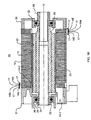
- Figs. 1A and 1B illustrate, respectively, an end view and cross-section view of an electric motor 10 which uses a stator assembly 12 that makes use of interconnect blades 14 and disks 16 to provide the stator windings.
- the motor 10 includes a stator assembly 12 and rotor assembly 20.
- the motor 10 is of the inside rotor type in which the rotor 20 is disposed along a central axis A to turn inside of the stator 12.
- the rotor 20 and stator 12 assemblies are held in position by a front motor housing 30 and rear motor housing 31.
- the housings 30 and 31, which maybe formed of aluminum, steel or other suitable metal, rotatably secure the rotor assembly 20 through front and rear bearings 32 and 33.
- the rotor assembly 20 consists of an outer sleeve 21, an inner rotor shaft 22, magnet bars 23, retaining rings 24, washers 25, tolerance rings 26, and pinion 27.
- the rotor assembly 20, which is well known in the art, uses the outer rotor sleeve 21 to retain a number of magnet bars 23 along the length thereof.
- the retaining rings 24 and washers 25 keep the rotor assembly 20 positioned within the bearings 32 and 33.
- a tolerance ring 26 may be inserted between the rear bearing 33 and the sidewall of the rear motor housing 31 to make the seating of the bearing 33 less critical.
- the pinion 27 is inserted in the front end of the rotor shaft 22 and typically couples mechanically to the device be driven by the motor 10.
- stator assembly 12 which consists of a number of blades 14 extending along the length of the stator 12, back iron washers 15, interconnect disks 16, and insulator disks 17.
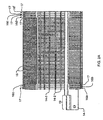
- Figs. 2A and 2B show the stator assembly 12 in more detail.
- the stator 12 includes a frame built up from a number of back iron washers 15 that are laminated together.
- the back iron washers 15 are formed of a nickle-iron alloy or other suitable ferrous material. The laminations help reduce eddy currents in the stator 12.
- On either end of the back iron washer 15 assembly are a series of interconnect disks 16 spaced apart by insulator disks 17.
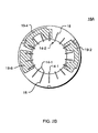
- interconnect disk 16A is shown in the plan view of Fig. 2B.
- the interconnect disk 16A is formed of an annular ring of insulating material, such as a ceramic containing 96% alumina.
- the inner circumference of the disk 16A has formed therein a number of slots 18 within which are placed the blades 14. In the illustrated configuration, there are a total number of eighteen slots 18 around the inner circumference.
- the blade pieces 14 actually are provided as two types, a stepped blade piece 14-1 and straight blade piece 14-2. Most of the pieces are of the straight blade 14-2 variety; there are however three stepped blade pieces 14-1 provided in the illustrated embodiment.
- the three stepped blades 14-1 correspond to each of the three phases of the windings of the stator assembly 12.
- the blade pieces 14 are formed of a suitable conductive material such as a copper-molybdenum laminate.
- the blade pieces 14-1 and 14-2 serve as current conductors to take the place of more typical winding wires found in a stator. Operating in conjunction with conductive metalization layers formed in a particular pattern on the various interconnect disks 16, the blades 14 provide circuit paths for current flow and thus serve as the various winding phases of the motor 10.
- FIG. 3 an exploded view of the interconnect disks 16 illustrates the manner in which the blades 14-1 and 14-2 are electrically interconnected. (The blades 14-1 and 14-2 are not shown in Fig. 3 for clarity.)
- a given blade 14 carries current from one end of the stator 12 to the other; the interconnect disks 16 serve as "end turns,” causing the current received from one blade 14 to reverse direction, and then return down the stator in the opposite direction.
- Each stepped blade piece 14-1 provides an end tab 19 which is brought out from the stator assembly 12 to provide an interconnection to one of the three phase drive signals required.
- interconnect disks 16A, 16B and 16C are disposed at the rear end of the stator assembly 12.
- Three other interconnect disks 16D, 16E, and 16F are placed at the front end of the stator assembly 12.
- the lines with arrows indicate the current flow from and through the various interconnect disks 16 and metalization layers formed thereon.
- interconnect disk 16A there is a slot 18-1 associated with a corresponding stepped blade piece 14-1 that provides the input current.
- the blade piece 14-1 is inserted in slots 18-1 that are located in a corresponding radial location in each of the five other disks 16B through 16F.
- the slot 18-1 is formed in a portion of the interconnect disk 16A that has only ceramic and no conductive metalization surrounding it. Therefore, the current continues to pass along the blade piece 14-1 to the next disk 16B.
- the current reaches disk 16-D at slot 18-1. At this radial position there is contained a portion of a metalization pad 19-1. The current thus enters the metalization pad 19-1 and is carried over to slot 18-4 in disk 16D. Although current will also continue down the remaining length of the blade piece 14-1, the corresponding slots 18-1 in disk 16E and 16F are in a ceramic portion of their respective disk, and therefore, no current will flow through them.
- a second metalization pad 19-2 provides for yet another change in the current direction back towards the front of the stator 12.
- current flows through the corresponding blade piece 14-7 through slots 18-7 in disks 16B and 16C until it encounters slot 18-7 in disk 16 adjacent metalization pad 19-3.
- Pad 19-3 causes current to again turn back towards the of the stator 12 until it reaches slot 18-10 in disk 16A.
- the current is turned around yet again and travels toward the front of the stator through blade 14-2 inserted in slots 18-13.
- a final turn is made through metalization pad 19-5. The current makes its final trip back "up" through slots 18-16.
- a final metalization pad 19-6 in disk 16A serves as a common connection point for the three phases of the motor which are connected in a "Y" electrical configuration.
- the pad 19-6 can either be allowed to electrically float or can be brought out to a case ground position.
- Fig. 3 illustrates an arrangement of disks 16 and blades 14 that provides a three phase-single turn motor, other phase and multiple turn motors can be provided by appropriate arrangement of the pads 19.
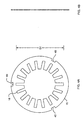
- Figs. 4A and 4B are a more detailed view of back iron washers 15. These washers are formed of a nickel iron alloy such as "Carpenter 49” or other suitable ferrous material. “Carpenter 49” is available from Carpenter Technology Corporation of Wyomissing, Pennsylvania.
- the back iron washers 15 are formed as annular rings of material having slots 18 on an inner diameter thereof, in the same manner that slots 18 were formed in the disks 16. The slots 18 are necessary to allow the blades 14 to pass through.
- Registration slots 40 may be formed in the outer diameter of the back iron washer 15 to assist with assembly and lamination process.
- each single back iron washer 15 has a thickness of approximately 0.010 inches.
- the back iron washers are built to lamination height of approximately 3 inches.
- the outer diameter for this motor is approximately 1.2 inches with a dimension D1 between the outboard ends of the slots 18 being approximately 1.01 inches.
- a motor of this size configured as shown is expected to provide approximately 1 1 ⁇ 2 horsepower.
- Figs. 5A, 5B and 5C show one of the interconnect disks 16A in greater detail.
- the disks 16A includes eighteen slots 18 formed in the inner diameter.
- the disk 16A is formed of a suitable structurally rigid, thermally stable, insulating material such as a ceramic containing 96% alumina.
- Metalization layers 19-2, 19-4 and 19-6 are formed on the face surfaces of the disk 16A.
- the metalization areas 19 may be formed in a number of ways such as by silver plating. A suitable set of art work images for such a process are shown in Figs. 6A and 6B.
- the pads 19 may be formed by a conductive material patch 29.
- a conductive patch 29 associated with pad 19-4 is shown in more detail in Fig. 7.
- the conductive patch 29 is formed in a desired shape, of course to accommodate the interconnection between the two conductive slots 18-4 and 18-7.
- the conductive patch 29 is formed of a composite conductive material such as a laminate of copper and molybdenum. In the preferred embodiment, this consists of a series of alternating layers of copper and molybdenum with copper being the two outer-most layers. By weight, the lamination is approximately 60% copper and 40% molybdenum. In the illustrated embodiment, the equal thickness layers of copper and molybdenum have a thickness dimension, D2, of approximately 0.005 inches.
- Figs. 8A and 8B are a more detailed view of one of the insulator disks 17.
- the insulator disk 17 is formed of the same material used for the substrate of interconnect disk 16. However, the insulator disks 17 are a bit thinners with a dimension D3 of approximately 0.12 inches. They have the slots 18 formed therein, of course, to accommodate the blades 14, however they contain no metalization layers. Insulator disks 17 insulate the exposed metalization pads 19 of a respective interconnect disk 16, to keep the adjacent interconnect disks 16 from electrically shorting to one another.
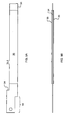
- Figs. 9A and 9B area more detailed view of a stepped blade piece 14-1.
- the stepped blade piece 14-1 is an electrically conductive unit that provides for current flow from one end of the stator assembly 12 to the other.
- the stepped blade 14-1 has a major portion consisting of a conductive blade 34.
- the conductive blade 34 is formed of a laminated conductive material such as the previously mentioned molybdenum and copper laminate. In this instance, a total thickness of 0.10 inches, as referenced by dimension by D4 can be provided by approximately 9 layers of material, again alternating the layers of copper and molybdenum.
- the tab or step 19 in blade piece 14-1 is used as an extension to provide for connection to the electrical phase control circuitry.
- the blade 14-1 can be formed entirely of this conductive material, in a preferred embodiment there is laminated on both sides thereof a insulator 35.
- the insulator 35 prevents the blade 14-1 from electrical contact with undesired portions of the stator assembly 12 and in particular the back iron disks 15.
- exposure of conductive material 34 is provided only on the ends of the blade 14-1 adjacent the front and rear ends of the state of assembly 12, where the slots 18 in the interconnect disks 16 are located.
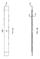
- Figs. 10A and 10B are more detailed views of a straight blade piece 14-2. These blade pieces 14-2 do not require the step 19, as they provide connection only between the disks 16 on either end of the stator 12, and do not need to provide connections out to the drive circuitry.
- the construction is otherwise the same as for the stepped blade piece 14-1, consisting of the conductive material 34 with outer insulating ceramic layers 35.
- the outer layers 35 may be formed from a suitable insulating ceramic which is brazed to the conductive portion 34.
- the use of the laminated conductive material for the blades 14 provide for superior performance.
- Brazing can be used to connect the conductive blade portions 14 to the ceramic molybdenum laminate presented by the disks 16. Because of the similarity in the coefficients of expansion of molybdenum and copper, the brasing process does not otherwise cause the laminations to separate as might otherwise be encountered with other materials.
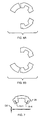
- Figs. 11A and 11B are a more detailed view of the insulator layer 35 used with the blade pieces 14-1 and 14-2.
- the layer 35 may be formed from a suitable ceramic material such as the 96% alumina previously described.
- a metalization layer 38 can be formed on one side thereof to assist in the braising process during assembly of the insulator layer to the blade pieces 14.
Abstract

Description
- The present invention relates to an electric machine such as a motor or generator of the induction type.
- A motor is an electromechanical device which converts electrical energy, delivered in the form of voltages or currents, into mechanical energy that is represented as rotational movement. One common type of motor consists of two major elements, a stator and a rotor. The stator typically includes a wire coil having a number of windings. The rotor typically includes permanent magnets. The rotor and stator are mechanically arranged such that the rotor can move freely with respect to the fixed stator. Electromagnetic interaction between the stator and rotor then causes the rotor to move for each polarity change in the stator windings. Other types of electric machines such as generators may be constructed in a similar fashion.
- In one type of motor, the stator is formed by laminating a number of disks formed of a ferrous material to provide a cylindrical stator housing. The core disks have formed therein tabs or tines that provide a structure around which are wrapped bare copper wire strands to form the windings. The stator housing provides a coaxial located open space into which is inserted the rotor assembly. The rotor assembly typically is made from a number of electromagnets spaced about a shaft. Typically, the magnets are contained or held with the shaft by an outer sleeve. The rotor assembly is rotatably supported mechanically within the stator housing by low friction bearings.
- Such motors have been widely accepted in industry for precision control applications, and they are presumably considered to perform reasonably well for their intended purpose. However, they are not without their shortcomings.
- It would be desirable to eliminate the need to provide for a number of windings in the stator assembly from a manufacturing perspective.
- It would also be desirable if the power generation or torque capability of a motor of a given size and weight could be increased.
- Furthermore, the reliability of such motors could be improved, given that in extended use the wire windings of the rotors may sometimes tend to short or wear out.
- The present invention is as claimed in the claims.
- The present invention is an electric machine, such as a brushless motor, in which the coil is formed by a set of electrically conductive blade structures disposed about an axis of a stator core. Electrical interconnection between the blades are provided, for example, by a set of disks disposed at one end of the blades. The disks electrically connect the blades in a correct circuit orientation to provide a desired number of turns and phases for the machine.
- The number of phases and number of turns associated with the motor may be changed by changing the circuit arrangement of the interconnect disks,
- The non-conductive portions of the interconnect disks may be provided by a ceramic or other alumina material.
- The blades and conductive portions of the interconnect disks are preferably formed from a material such as a copper and molybdenum laminate.
- The outer layers of the blades may have a portion thereof which mechanically contacts a back iron structure of the stator assembly, to provide a rigid, rugged stator structure. In such a configuration, an insulating material is also formed along the blades to prevent the blades from shorting to the back iron.
- Embodiments of the invention will now be described, by way of example only, with reference to the accompanying drawings, in which:
- Fig. 1A is an end view of a electric machine such as a brushless direct current motor constructed according to the invention.
- Fig. 1B is a cross-section view of the motor.
- Fig. 2A is a more detailed cross-section of the stator assembly and the rotor.
- Fig. 2B is a plan view of one of the interconnect disks.
- Fig. 3 is an exploded view showing the arrangement of interconnect disks for a single turn, three phase motor illustrating how the disks and blades provide the motor windings.
- Figs. 4A and 4B are respectively a plan view and cross-section view of a back iron washer from which the body of the stator is formed.
- Figs. 5A, 5B and 5C are front, cross-section, and rear views of a particular one of the interconnect disks.
- Figs. 6A and 6B show metalization patterns for the interconnect disk.
- Fig. 7 is a more detailed view of conductive pad that is mounted to the interconnect disk to provide for interconnection between the blades.
- Figs. 8A and 8B are a front and cross-section views of isolator disks.
- Figs. 9A and 9B are plan and cross-section views of one type of blade having a stepped portion to provide an electrical connection to driver circuits.
- Figs. 10A and 10B are views of a second type of blade that provides for current flow from one end of the stator to the other.
- Figs. 11A and 11B are a more detailed view of a insulator ceramic piece that is braised to the blades in a preferred embodiment.
- The foregoing and other objects, features and advantages of the invention will be apparent from the following more particular description of preferred embodiments of the invention, as illustrated in the accompanying drawings in which like reference characters refer to the same parts throughout the different views. The drawings are not necessarily to scale, emphasis instead being placed upon illustrating the principles of the invention.
- The foregoing and other objects, features and advantages of embodiments of the invention will be apparent from the following more particular description of preferred
- Figs. 1A and 1B illustrate, respectively, an end view and cross-section view of an
electric motor 10 which uses a stator assembly 12 that makes use of interconnect blades 14 and disks 16 to provide the stator windings. - More particularly, the
motor 10 includes a stator assembly 12 androtor assembly 20. Themotor 10 is of the inside rotor type in which therotor 20 is disposed along a central axis A to turn inside of the stator 12. Therotor 20 and stator 12 assemblies are held in position by afront motor housing 30 andrear motor housing 31. Thehousings rotor assembly 20 through front andrear bearings - The
rotor assembly 20 consists of anouter sleeve 21, aninner rotor shaft 22, magnet bars 23,retaining rings 24,washers 25,tolerance rings 26, and pinion 27. Therotor assembly 20, which is well known in the art, uses theouter rotor sleeve 21 to retain a number of magnet bars 23 along the length thereof. Theretaining rings 24 andwashers 25 keep therotor assembly 20 positioned within thebearings tolerance ring 26 may be inserted between therear bearing 33 and the sidewall of therear motor housing 31 to make the seating of the bearing 33 less critical. The pinion 27 is inserted in the front end of therotor shaft 22 and typically couples mechanically to the device be driven by themotor 10. - Of particular interest to the present invention is the construction of the stator assembly 12, which consists of a number of blades 14 extending along the length of the stator 12, back
iron washers 15, interconnect disks 16, andinsulator disks 17. - Figs. 2A and 2B show the stator assembly 12 in more detail. The stator 12 includes a frame built up from a number of
back iron washers 15 that are laminated together. Theback iron washers 15 are formed of a nickle-iron alloy or other suitable ferrous material. The laminations help reduce eddy currents in the stator 12. On either end of theback iron washer 15 assembly are a series of interconnect disks 16 spaced apart byinsulator disks 17. - A particular one of the
interconnect disks 16A is shown in the plan view of Fig. 2B. As can be seen best in this view, theinterconnect disk 16A is formed of an annular ring of insulating material, such as a ceramic containing 96% alumina. - The inner circumference of the
disk 16A has formed therein a number ofslots 18 within which are placed the blades 14. In the illustrated configuration, there are a total number of eighteenslots 18 around the inner circumference. - The blade pieces 14 actually are provided as two types, a stepped blade piece 14-1 and straight blade piece 14-2. Most of the pieces are of the straight blade 14-2 variety; there are however three stepped blade pieces 14-1 provided in the illustrated embodiment. The three stepped blades 14-1 correspond to each of the three phases of the windings of the stator assembly 12. As mentioned previously, the blade pieces 14 are formed of a suitable conductive material such as a copper-molybdenum laminate.
- The blade pieces 14-1 and 14-2 serve as current conductors to take the place of more typical winding wires found in a stator. Operating in conjunction with conductive metalization layers formed in a particular pattern on the various interconnect disks 16, the blades 14 provide circuit paths for current flow and thus serve as the various winding phases of the
motor 10. - Turning attention now to Fig. 3, an exploded view of the interconnect disks 16 illustrates the manner in which the blades 14-1 and 14-2 are electrically interconnected. (The blades 14-1 and 14-2 are not shown in Fig. 3 for clarity.) In general, a given blade 14 carries current from one end of the stator 12 to the other; the interconnect disks 16 serve as "end turns," causing the current received from one blade 14 to reverse direction, and then return down the stator in the opposite direction.
- Each stepped blade piece 14-1 provides an
end tab 19 which is brought out from the stator assembly 12 to provide an interconnection to one of the three phase drive signals required. - In the illustrated configuration, three
interconnect disks - For example, consider the current path for one phase of the windings. Starting at
interconnect disk 16A, there is a slot 18-1 associated with a corresponding stepped blade piece 14-1 that provides the input current. The blade piece 14-1 is inserted in slots 18-1 that are located in a corresponding radial location in each of the five other disks 16B through 16F. - Current enters the stator assembly 12 at the stepped blade piece 14-1 positioned in slot 18-1. The slot 18-1 is formed in a portion of the
interconnect disk 16A that has only ceramic and no conductive metalization surrounding it. Therefore, the current continues to pass along the blade piece 14-1 to the next disk 16B. - At disk 16B is encountered another slot 18-1 which has no metalization surrounding it. Current thus continues to flow along the blade piece 14-1 to the
next disk 16C, which again contains no metalization adjacent its slot 18-1. - Continuing along the stator body formed by the
back iron 15, the current reaches disk 16-D at slot 18-1. At this radial position there is contained a portion of a metalization pad 19-1. The current thus enters the metalization pad 19-1 and is carried over to slot 18-4 in disk 16D. Although current will also continue down the remaining length of the blade piece 14-1, the corresponding slots 18-1 in disk 16E and 16F are in a ceramic portion of their respective disk, and therefore, no current will flow through them. - Thus, all of the current flowing in the blade piece 14-1 is turned around, in effect, by the metalization pad 19-1, and is now presented to the slot 18-4 in disk 16D. As indicated by the arrows in the drawing, the current then travels in the "up direction," returning to
disk 16C at slot 18-4 and disk 16B at 18-4. At the radial slot 18-4, thesedisks 16C and 16B, again contain ceramic only. However, upon reaching slot 18-4 indisk 16A, a second metalization pad 19-2 is encountered in thedisk 16A, causing the current to be forwarded to slot 18-7. - A second blade piece 14-4 inserted in the slots 18-4 associated with each of
disks 16A through 16F then carries the current from the front to the back of the stator 12. - A second metalization pad 19-2 provides for yet another change in the current direction back towards the front of the stator 12. In this instance, current flows through the corresponding blade piece 14-7 through slots 18-7 in
disks 16B and 16C until it encounters slot 18-7 in disk 16 adjacent metalization pad 19-3. Pad 19-3 causes current to again turn back towards the of the stator 12 until it reaches slot 18-10 indisk 16A. At this point, the current is turned around yet again and travels toward the front of the stator through blade 14-2 inserted in slots 18-13. Upon reaching disk 16D at slot 18-13, a final turn is made through metalization pad 19-5. The current makes its final trip back "up" through slots 18-16. - A final metalization pad 19-6 in
disk 16A serves as a common connection point for the three phases of the motor which are connected in a "Y" electrical configuration. The pad 19-6 can either be allowed to electrically float or can be brought out to a case ground position. - Having described how one phase of the current path flows through the various blade pieces 14 and interconnect disks 16, it can be readily understood how the other metalization pads and
slots 18 cooperate to provide the two other current phases. - It should also be appreciated that while Fig. 3 illustrates an arrangement of disks 16 and blades 14 that provides a three phase-single turn motor, other phase and multiple turn motors can be provided by appropriate arrangement of the
pads 19. - Figs. 4A and 4B are a more detailed view of
back iron washers 15. These washers are formed of a nickel iron alloy such as "Carpenter 49" or other suitable ferrous material. "Carpenter 49" is available from Carpenter Technology Corporation of Wyomissing, Pennsylvania. Theback iron washers 15 are formed as annular rings ofmaterial having slots 18 on an inner diameter thereof, in the same manner thatslots 18 were formed in the disks 16. Theslots 18 are necessary to allow the blades 14 to pass through.Registration slots 40 may be formed in the outer diameter of theback iron washer 15 to assist with assembly and lamination process. - In the illustrated embodiment, each single
back iron washer 15 has a thickness of approximately 0.010 inches. In a typical configuration, the back iron washers are built to lamination height of approximately 3 inches. The outer diameter for this motor is approximately 1.2 inches with a dimension D1 between the outboard ends of theslots 18 being approximately 1.01 inches. A motor of this size configured as shown is expected to provide approximately 1 ½ horsepower. - Figs. 5A, 5B and 5C show one of the
interconnect disks 16A in greater detail. As previously explained, thedisks 16A includes eighteenslots 18 formed in the inner diameter. Thedisk 16A is formed of a suitable structurally rigid, thermally stable, insulating material such as a ceramic containing 96% alumina. - Metalization layers 19-2, 19-4 and 19-6 are formed on the face surfaces of the
disk 16A. In a preferred embodiment, there aremetalization layers 19 associated with each face of thedisk 16A. Havingconductive layers 19 on both sides of the disk 16 is not completely necessary for operation of the invention. However it is preferred, as this provides twice the current handling capability for given size ofdisk 16A. - The
metalization areas 19 may be formed in a number of ways such as by silver plating. A suitable set of art work images for such a process are shown in Figs. 6A and 6B. - In the preferred embodiment there is also a conductive material layer braised to disk 16 to provide the
metalization pads 19. In particular, thepads 19 may be formed by aconductive material patch 29. - A
conductive patch 29 associated with pad 19-4 is shown in more detail in Fig. 7. Theconductive patch 29 is formed in a desired shape, of course to accommodate the interconnection between the two conductive slots 18-4 and 18-7. Theconductive patch 29 is formed of a composite conductive material such as a laminate of copper and molybdenum. In the preferred embodiment, this consists of a series of alternating layers of copper and molybdenum with copper being the two outer-most layers. By weight, the lamination is approximately 60% copper and 40% molybdenum. In the illustrated embodiment, the equal thickness layers of copper and molybdenum have a thickness dimension, D2, of approximately 0.005 inches. - Figs. 8A and 8B are a more detailed view of one of the
insulator disks 17. Theinsulator disk 17 is formed of the same material used for the substrate of interconnect disk 16. However, theinsulator disks 17 are a bit thinners with a dimension D3 of approximately 0.12 inches. They have theslots 18 formed therein, of course, to accommodate the blades 14, however they contain no metalization layers.Insulator disks 17 insulate the exposedmetalization pads 19 of a respective interconnect disk 16, to keep the adjacent interconnect disks 16 from electrically shorting to one another. - Figs. 9A and 9B area more detailed view of a stepped blade piece 14-1. The stepped blade piece 14-1 is an electrically conductive unit that provides for current flow from one end of the stator assembly 12 to the other. The stepped blade 14-1 has a major portion consisting of a
conductive blade 34. Theconductive blade 34 is formed of a laminated conductive material such as the previously mentioned molybdenum and copper laminate. In this instance, a total thickness of 0.10 inches, as referenced by dimension by D4 can be provided by approximately 9 layers of material, again alternating the layers of copper and molybdenum. - The tab or step 19 in blade piece 14-1 is used as an extension to provide for connection to the electrical phase control circuitry.
- Although the blade 14-1 can be formed entirely of this conductive material, in a preferred embodiment there is laminated on both sides thereof a
insulator 35. Theinsulator 35 prevents the blade 14-1 from electrical contact with undesired portions of the stator assembly 12 and in particular theback iron disks 15. Thus, exposure ofconductive material 34 is provided only on the ends of the blade 14-1 adjacent the front and rear ends of the state of assembly 12, where theslots 18 in the interconnect disks 16 are located. - Figs. 10A and 10B are more detailed views of a straight blade piece 14-2. These blade pieces 14-2 do not require the
step 19, as they provide connection only between the disks 16 on either end of the stator 12, and do not need to provide connections out to the drive circuitry. The construction is otherwise the same as for the stepped blade piece 14-1, consisting of theconductive material 34 with outer insulating ceramic layers 35. Theouter layers 35 may be formed from a suitable insulating ceramic which is brazed to theconductive portion 34. - We have found in practice that the use of the laminated conductive material for the blades 14 provide for superior performance. Brazing can be used to connect the conductive blade portions 14 to the ceramic molybdenum laminate presented by the disks 16. Because of the similarity in the coefficients of expansion of molybdenum and copper, the brasing process does not otherwise cause the laminations to separate as might otherwise be encountered with other materials.
- Figs. 11A and 11B are a more detailed view of the
insulator layer 35 used with the blade pieces 14-1 and 14-2. Thelayer 35 may be formed from a suitable ceramic material such as the 96% alumina previously described. Ametalization layer 38 can be formed on one side thereof to assist in the braising process during assembly of the insulator layer to the blade pieces 14. - While this invention has been particularly shown and described with references to preferred embodiments thereof, it will be understood by those skilled in the art that various changes in form and details may be made therein without departing from the scope of the invention encompassed by the appended claims.
Claims (15)
- An electric machine comprising:a rotor consisting of a shaft having electromagnetic material portions therein, the rotor arranged to rotate freely about a central axis; anda stator including:a plurality of conductive blades arranged axially about the central axis; anda planar interconnect structure, disposed at one end of blades, to provide interconnections for current flow through the blades.
- An electric machine as in claim 1 wherein the planar interconnect structure is formed as a disk.
- An electric machine as in claim 2 wherein the interconnect structure is provided by a plurality of disks located at each of two ends of the blades.
- An electric machine as in claim 3 wherein the interconnect structure disks at a given end are separated from one another by an insulator disk.
- An electric machine as in claim 2 wherein the disk is formed using an insulating material as a substrate, with conductive pads formed thereon in selected locations where the blades contact the planar interconnect structure.
- An electric machine as in any preceding claim wherein the blades have a stepped structure at one end to provide for connection to electric circuitry.
- An electric machine as in claim 6 wherein at least some of the blades are of a shortened length such that they do not extend beyond the interconnect structure.
- An electric machine as in any preceding claim wherein the blade is formed of a copper molybdenum laminate.
- An electric machine as in any preceding claim wherein the interconnect structure has conductive portions formed of a copper molybdenum laminate.
- An electric machine as in any preceding claim wherein the blades have insulation formed thereon along a central portion.
- An electric machine as in any preceding claim wherein the interconnect structure has metalization formed on both sides thereof.
- An electric machine as in any preceding claim wherein the machine is arranged to be a motor.
- An electric machine as in claim 12 wherein the interconnect structure provides a three-phase, single-turn motor.
- An electric machine as in one of claims 1 to 11 wherein the machine is arranged to be a generator.
- An electric machine as in claim 1 additionally comprising:a stator body composed of a plurality of back iron disks laminated together.
Applications Claiming Priority (2)
| Application Number | Priority Date | Filing Date | Title |
|---|---|---|---|
| US605157 | 2000-06-28 | ||
| US09/605,157 US6538356B1 (en) | 2000-06-28 | 2000-06-28 | Electric machine using composite blade structure |
Publications (3)
| Publication Number | Publication Date |
|---|---|
| EP1168574A2 true EP1168574A2 (en) | 2002-01-02 |
| EP1168574A3 EP1168574A3 (en) | 2003-10-08 |
| EP1168574B1 EP1168574B1 (en) | 2005-12-07 |
Family
ID=24422492
Family Applications (1)
| Application Number | Title | Priority Date | Filing Date |
|---|---|---|---|
| EP01305588A Expired - Lifetime EP1168574B1 (en) | 2000-06-28 | 2001-06-28 | Electrical machine |
Country Status (7)
| Country | Link |
|---|---|
| US (2) | US6538356B1 (en) |
| EP (1) | EP1168574B1 (en) |
| JP (1) | JP4471538B2 (en) |
| AT (1) | ATE312424T1 (en) |
| CA (1) | CA2351812C (en) |
| DE (1) | DE60115544T2 (en) |
| HK (1) | HK1043446A1 (en) |
Cited By (10)
| Publication number | Priority date | Publication date | Assignee | Title |
|---|---|---|---|---|
| EP1742330A1 (en) * | 2005-07-08 | 2007-01-10 | Siemens Aktiengesellschaft | Winding head of a stator, stator of an electric machine and turbogenerator |
| EP1571750A3 (en) * | 2004-03-02 | 2007-03-28 | Hitachi, Ltd. | Rotary machine |
| DE10312441B4 (en) * | 2003-03-20 | 2009-02-26 | Compact Dynamics Gmbh | Traveling wave machine |
| EP2112748A1 (en) * | 2008-04-24 | 2009-10-28 | Magneti Marelli Holding S.p.A. | Multiphase synchronous electric motor and/or generator for a transport vehicle |
| WO2010054651A3 (en) * | 2008-11-14 | 2010-07-08 | Feaam Gmbh | Electric machine |
| US8076817B2 (en) | 2008-04-24 | 2011-12-13 | MAGNETI MARELLI S.p.A. | Electric motor with bar winding and connection plates |
| EP2621062A1 (en) * | 2012-01-26 | 2013-07-31 | Siemens Aktiengesellschaft | Connecting device |
| EP2784911A1 (en) * | 2013-03-27 | 2014-10-01 | Maxon Motor AG | Stator for a high temperature electric motor and electric motor |
| WO2017143328A1 (en) | 2016-02-18 | 2017-08-24 | Abb Schweiz Ag | Windings for an electric machine |
| WO2018033761A1 (en) * | 2016-08-19 | 2018-02-22 | Aeristech Ltd | An electric machine and a stator with conductive bars and an end face assembly |
Families Citing this family (36)
| Publication number | Priority date | Publication date | Assignee | Title |
|---|---|---|---|---|
| AUPP702498A0 (en) * | 1998-11-09 | 1998-12-03 | Silverbrook Research Pty Ltd | Image creation method and apparatus (ART77) |
| JP3733316B2 (en) * | 2001-10-26 | 2006-01-11 | 住友電装株式会社 | Centralized power distribution member for thin brushless motor for vehicles |
| JP2003148343A (en) * | 2001-11-08 | 2003-05-21 | Sanden Corp | Motor-driven compressor |
| US7362001B2 (en) * | 2002-10-28 | 2008-04-22 | Toyota Jidosha Kabushiki Kaisha | Generator-motor |
| EP1557931A4 (en) * | 2002-10-28 | 2010-11-17 | Toyota Motor Co Ltd | Generator-motor |
| US8910718B2 (en) * | 2003-10-01 | 2014-12-16 | Schlumberger Technology Corporation | System and method for a combined submersible motor and protector |
| US8615487B2 (en) | 2004-01-23 | 2013-12-24 | Garrison Gomez | System and method to store and retrieve identifier associated information content |
| US6958561B2 (en) * | 2004-02-27 | 2005-10-25 | Unique Product & Design Co., Ltd. | Stator winding structure of a motor or a generator |
| DE502005000248D1 (en) * | 2005-03-17 | 2007-02-01 | Zahnradfabrik Friedrichshafen | Stator for an electric machine |
| US7495363B2 (en) * | 2005-12-21 | 2009-02-24 | Raytheon Company | Maximum conductor motor and method of making same |
| US7592728B2 (en) * | 2006-05-10 | 2009-09-22 | Robert M. Jones | Electric machine having segmented stator |
| US8028396B2 (en) * | 2006-07-18 | 2011-10-04 | Robert M. Jones | Automatic wire winding of inside brushless stator |
| DE102006038582A1 (en) * | 2006-08-17 | 2008-02-21 | Siemens Ag | Bar rotor winding profile |
| JP4787363B2 (en) * | 2006-10-04 | 2011-10-05 | パスウェイ メディカル テクノロジーズ インコーポレイテッド | Medical catheter |
| US20100038988A1 (en) * | 2008-08-12 | 2010-02-18 | Gannon Ramy | Stator and Method of Making the Same |
| US20090085411A1 (en) * | 2008-08-15 | 2009-04-02 | Zhu Qiang | Propulsion Device Using Lorentz Force |
| SG175040A1 (en) * | 2009-04-03 | 2011-11-28 | Robert M Jones | Over-molded liquid cooled three-stack motor |
| US20110095635A1 (en) * | 2009-05-13 | 2011-04-28 | Heung Yeung Li | Various motor assembly |
| JP5762671B2 (en) * | 2009-05-20 | 2015-08-12 | 日立工機株式会社 | Disc grinder |
| US20130181545A1 (en) * | 2009-06-29 | 2013-07-18 | Dah-Prong Lai | Drive device capable of generating a driving output based on a magnetic field |
| TW201101671A (en) * | 2009-06-29 | 2011-01-01 | da-peng Lai | Motor |
| IT1401829B1 (en) * | 2010-09-29 | 2013-08-28 | Magneti Marelli Spa | ELECTRIC MACHINE PRESENTING A STATIC ROLL WITH RIGID BARS AND ITS CONSTRUCTION METHOD |
| DE102010056120A1 (en) * | 2010-12-20 | 2012-07-05 | C. & E. Fein Gmbh | Interconnection device for an electric motor |
| US8736127B2 (en) * | 2011-02-17 | 2014-05-27 | Innerpoint Energy Corporation | Dynamoelectric device and method of forming the same |
| JP5389109B2 (en) | 2011-07-21 | 2014-01-15 | 本田技研工業株式会社 | Rotating electric machine stator |
| WO2014011811A1 (en) * | 2012-07-11 | 2014-01-16 | Remy Technologies, Llc | Buss bar assembly having printed buss bar plates |
| DE102013206593A1 (en) * | 2013-04-12 | 2014-10-30 | Siemens Aktiengesellschaft | Flow-type machine in lightweight design |
| JP6126897B2 (en) | 2013-04-24 | 2017-05-10 | 本田技研工業株式会社 | Stator for rotating electrical machine and method for manufacturing the same |
| US20160254737A1 (en) * | 2015-02-26 | 2016-09-01 | James W. Purvis | Electromagnetic Angular Acceleration Propulsion System |
| DE102015014509A1 (en) * | 2015-11-11 | 2017-05-11 | Bergische Universität Wuppertal | Electric drive system |
| US20180233987A1 (en) * | 2016-12-22 | 2018-08-16 | General Dynamics - Ots, Inc. | Low-voltage motor and method for making the same |
| US10528023B2 (en) | 2016-12-22 | 2020-01-07 | General Dynamics-OTS. Inc. | Electric motor drive system for low-voltage motor |
| DE102017126880A1 (en) * | 2017-11-15 | 2019-05-16 | Deutsches Zentrum für Luft- und Raumfahrt e.V. | Electrical unit with a winding and method for producing such a unit |
| KR20200008835A (en) * | 2018-07-17 | 2020-01-29 | 현대자동차주식회사 | Coil wiring unit of drive motor for vehicle and fabrication method thereof |
| DE102019112100A1 (en) * | 2019-05-09 | 2020-11-12 | Deutsches Zentrum für Luft- und Raumfahrt e.V. | Electrical assembly with a winding and method for its manufacture |
| JP7442409B2 (en) | 2020-08-06 | 2024-03-04 | 産業振興株式会社 | Motor copper coil recovery device |
Citations (6)
| Publication number | Priority date | Publication date | Assignee | Title |
|---|---|---|---|---|
| US1512693A (en) * | 1922-10-18 | 1924-10-21 | H Cuenod Sa Atel | Induction motor |
| GB1038011A (en) * | 1962-07-09 | 1966-08-03 | Alois Kaltenbach | Improvements in or relating to fractional horse-power two-phase or multi-phase dynamo-electric machines |
| US4039875A (en) * | 1975-11-07 | 1977-08-02 | Computer Devices Corporation | Method and apparatus for interconnecting stator coils |
| JPS61203839A (en) * | 1985-03-07 | 1986-09-09 | Toshiba Corp | Rotor coil of rotary electric machine |
| US4689023A (en) * | 1985-08-27 | 1987-08-25 | The Superior Electric Company | Programmable electrical connector |
| US5804902A (en) * | 1994-04-06 | 1998-09-08 | Hill; Wolfgang | Multi-phase electric machine with joined conductor lanes |
Family Cites Families (20)
| Publication number | Priority date | Publication date | Assignee | Title |
|---|---|---|---|---|
| US1512613A (en) * | 1924-02-23 | 1924-10-21 | Martin Langner | Railroad clamp |
| US4115915A (en) * | 1975-07-31 | 1978-09-26 | General Electric Company | Process for manufacturing motor having windings constructed for automated assembly |
| US4224543A (en) * | 1978-08-01 | 1980-09-23 | Rapidsyn Co. | Printed circuit terminal for interconnecting stator coils |
| US4677329A (en) * | 1984-07-12 | 1987-06-30 | Black & Decker, Inc. | Sub-assembly for electric motor with stator terminal connection means |
| DE3710659A1 (en) * | 1987-03-31 | 1988-10-13 | Standard Elektrik Lorenz Ag | ELECTRONICALLY COMMUTED, COLLECTORLESS DC MOTOR |
| US4922145A (en) | 1988-11-17 | 1990-05-01 | Eastman Kodak Company | Stepper motor |
| DE4130016A1 (en) * | 1990-12-24 | 1993-03-11 | Erich Rabe | ELECTRONICALLY COMMUTED DC GENERATOR |
| US5191255A (en) | 1991-02-19 | 1993-03-02 | Magnetospheric Power Corp. Ltd. | Electromagnetic motor |
| FR2678787B1 (en) * | 1991-07-05 | 1993-10-29 | Ecia | IMPROVED STRUCTURE FOR ELECTRONICALLY SWITCHED DIRECT CURRENT MOTOR. |
| DE59407670D1 (en) * | 1993-04-16 | 1999-03-04 | Heinze Dyconex Patente | Core for electrical connection substrates and electrical connection substrates with a core, and method for the production thereof |
| JP3182301B2 (en) | 1994-11-07 | 2001-07-03 | キヤノン株式会社 | Microstructure and method for forming the same |
| DE19544830A1 (en) * | 1995-12-01 | 1997-06-05 | Mulfingen Elektrobau Ebm | Stator for electric motors |
| US6169354B1 (en) | 1996-05-24 | 2001-01-02 | Halo Data Devices, Inc. | Thin film electric motors |
| BR9801695B1 (en) | 1997-05-26 | 2009-08-11 | rotary electric machine. | |
| JPH11103551A (en) * | 1997-09-29 | 1999-04-13 | Sawafuji Electric Co Ltd | Coil connection structure in outer rotor type multi-pole generator |
| JP3881757B2 (en) * | 1997-11-13 | 2007-02-14 | 澤藤電機株式会社 | Connection terminal for stator |
| KR100301480B1 (en) | 1998-07-13 | 2001-09-06 | 구자홍 | Stator core for linear motor and stator manufacturing method using same |
| DE19842170A1 (en) * | 1998-09-15 | 2000-03-16 | Wilo Gmbh | Contacting motor windings |
| DE29816561U1 (en) | 1998-09-15 | 1998-12-17 | Wang Yu Yan | Double-sided brushless DC motor with non-ferrous core and axial magnetic field of the permanent magnet type |
| JP2000156963A (en) * | 1998-11-19 | 2000-06-06 | Moriyama Kogyo Kk | Detecting apparatus for position of magnetic pole in brushless dc motor and annular sheet with thin sheet- like magnet |
-
2000
- 2000-06-28 US US09/605,157 patent/US6538356B1/en not_active Expired - Lifetime
-
2001
- 2001-06-27 CA CA002351812A patent/CA2351812C/en not_active Expired - Lifetime
- 2001-06-28 DE DE60115544T patent/DE60115544T2/en not_active Expired - Lifetime
- 2001-06-28 EP EP01305588A patent/EP1168574B1/en not_active Expired - Lifetime
- 2001-06-28 AT AT01305588T patent/ATE312424T1/en not_active IP Right Cessation
- 2001-06-28 JP JP2001196399A patent/JP4471538B2/en not_active Expired - Lifetime
-
2002
- 2002-06-28 HK HK02104876.9A patent/HK1043446A1/en unknown
- 2002-10-30 US US10/285,384 patent/US6889420B2/en not_active Expired - Lifetime
Patent Citations (6)
| Publication number | Priority date | Publication date | Assignee | Title |
|---|---|---|---|---|
| US1512693A (en) * | 1922-10-18 | 1924-10-21 | H Cuenod Sa Atel | Induction motor |
| GB1038011A (en) * | 1962-07-09 | 1966-08-03 | Alois Kaltenbach | Improvements in or relating to fractional horse-power two-phase or multi-phase dynamo-electric machines |
| US4039875A (en) * | 1975-11-07 | 1977-08-02 | Computer Devices Corporation | Method and apparatus for interconnecting stator coils |
| JPS61203839A (en) * | 1985-03-07 | 1986-09-09 | Toshiba Corp | Rotor coil of rotary electric machine |
| US4689023A (en) * | 1985-08-27 | 1987-08-25 | The Superior Electric Company | Programmable electrical connector |
| US5804902A (en) * | 1994-04-06 | 1998-09-08 | Hill; Wolfgang | Multi-phase electric machine with joined conductor lanes |
Non-Patent Citations (1)
| Title |
|---|
| PATENT ABSTRACTS OF JAPAN vol. 011, no. 036 (E-477), 3 February 1987 (1987-02-03) -& JP 61 203839 A (TOSHIBA CORP), 9 September 1986 (1986-09-09) * |
Cited By (19)
| Publication number | Priority date | Publication date | Assignee | Title |
|---|---|---|---|---|
| DE10312441B4 (en) * | 2003-03-20 | 2009-02-26 | Compact Dynamics Gmbh | Traveling wave machine |
| CN100583598C (en) * | 2004-03-02 | 2010-01-20 | 株式会社日立制作所 | Rotary machine |
| EP1571750A3 (en) * | 2004-03-02 | 2007-03-28 | Hitachi, Ltd. | Rotary machine |
| US7417351B2 (en) | 2004-03-02 | 2008-08-26 | Hitachi, Ltd. | Rotary machine |
| EP1742330A1 (en) * | 2005-07-08 | 2007-01-10 | Siemens Aktiengesellschaft | Winding head of a stator, stator of an electric machine and turbogenerator |
| US8076817B2 (en) | 2008-04-24 | 2011-12-13 | MAGNETI MARELLI S.p.A. | Electric motor with bar winding and connection plates |
| US8072114B2 (en) | 2008-04-24 | 2011-12-06 | MAGNETI MARELLI S.p.A. | Electric motor with bar winding and connection plates |
| EP2112748A1 (en) * | 2008-04-24 | 2009-10-28 | Magneti Marelli Holding S.p.A. | Multiphase synchronous electric motor and/or generator for a transport vehicle |
| US9318926B2 (en) | 2008-11-14 | 2016-04-19 | Feaam Gmbh | Electric machine |
| WO2010054651A3 (en) * | 2008-11-14 | 2010-07-08 | Feaam Gmbh | Electric machine |
| EP2621062A1 (en) * | 2012-01-26 | 2013-07-31 | Siemens Aktiengesellschaft | Connecting device |
| US9660495B2 (en) | 2013-03-27 | 2017-05-23 | Maxon Motor Ag | Stator for a high-temperature electric motor and electric motor |
| EP2784911A1 (en) * | 2013-03-27 | 2014-10-01 | Maxon Motor AG | Stator for a high temperature electric motor and electric motor |
| WO2017143328A1 (en) | 2016-02-18 | 2017-08-24 | Abb Schweiz Ag | Windings for an electric machine |
| EP3417530A4 (en) * | 2016-02-18 | 2019-10-23 | ABB Schweiz AG | Windings for an electric machine |
| US10951080B2 (en) | 2016-02-18 | 2021-03-16 | Abb Schweiz Ag | Windings for an electric machine |
| WO2018033761A1 (en) * | 2016-08-19 | 2018-02-22 | Aeristech Ltd | An electric machine and a stator with conductive bars and an end face assembly |
| CN109863668A (en) * | 2016-08-19 | 2019-06-07 | 艾瑞斯技术有限公司 | Motor and stator with conductive bar and end face component |
| CN109863668B (en) * | 2016-08-19 | 2023-04-14 | 艾瑞斯技术有限公司 | Motor and stator with conductive bar and end face assembly |
Also Published As
| Publication number | Publication date |
|---|---|
| JP2002051488A (en) | 2002-02-15 |
| US6889420B2 (en) | 2005-05-10 |
| DE60115544D1 (en) | 2006-01-12 |
| JP4471538B2 (en) | 2010-06-02 |
| US6538356B1 (en) | 2003-03-25 |
| HK1043446A1 (en) | 2002-09-13 |
| US20030173857A1 (en) | 2003-09-18 |
| ATE312424T1 (en) | 2005-12-15 |
| DE60115544T2 (en) | 2006-08-17 |
| EP1168574A3 (en) | 2003-10-08 |
| CA2351812C (en) | 2009-12-08 |
| EP1168574B1 (en) | 2005-12-07 |
| CA2351812A1 (en) | 2001-12-28 |
Similar Documents
| Publication | Publication Date | Title |
|---|---|---|
| CA2351812C (en) | Electric machine using composite blade structure | |
| US10778049B2 (en) | Stator assembly with stack of coated conductors | |
| EP1590871B1 (en) | Conductor optimized axial field rotary energy device | |
| US10355550B2 (en) | Methods and apparatus for reducing machine winding circulating current losses | |
| US6873085B2 (en) | Brushless motor | |
| US7795773B1 (en) | Electric actuator | |
| US20210066983A1 (en) | Stator assembly with stack of coated conductors | |
| WO2002075895A2 (en) | Homolar electric dc- motors/ -generators | |
| WO2024050085A1 (en) | Axial flux electric machine pole piece with conductive ribbons | |
| JP2024024492A (en) | motor | |
| CN117134522A (en) | Motor and method of operating motor |
Legal Events
| Date | Code | Title | Description |
|---|---|---|---|
| PUAI | Public reference made under article 153(3) epc to a published international application that has entered the european phase |
Free format text: ORIGINAL CODE: 0009012 |
|
| AK | Designated contracting states |
Kind code of ref document: A2 Designated state(s): AT BE CH CY DE DK ES FI FR GB GR IE IT LI LU MC NL PT SE TR |
|
| AX | Request for extension of the european patent |
Free format text: AL;LT;LV;MK;RO;SI |
|
| PUAL | Search report despatched |
Free format text: ORIGINAL CODE: 0009013 |
|
| AK | Designated contracting states |
Kind code of ref document: A3 Designated state(s): AT BE CH CY DE DK ES FI FR GB GR IE IT LI LU MC NL PT SE TR |
|
| AX | Request for extension of the european patent |
Extension state: AL LT LV MK RO SI |
|
| 17P | Request for examination filed |
Effective date: 20040327 |
|
| 17Q | First examination report despatched |
Effective date: 20040426 |
|
| AKX | Designation fees paid |
Designated state(s): AT BE CH CY DE DK ES FI FR GB GR IE IT LI LU MC NL PT SE TR |
|
| GRAP | Despatch of communication of intention to grant a patent |
Free format text: ORIGINAL CODE: EPIDOSNIGR1 |
|
| GRAS | Grant fee paid |
Free format text: ORIGINAL CODE: EPIDOSNIGR3 |
|
| GRAA | (expected) grant |
Free format text: ORIGINAL CODE: 0009210 |
|
| AK | Designated contracting states |
Kind code of ref document: B1 Designated state(s): AT BE CH CY DE DK ES FI FR GB GR IE IT LI LU MC NL PT SE TR |
|
| PG25 | Lapsed in a contracting state [announced via postgrant information from national office to epo] |
Ref country code: BE Free format text: LAPSE BECAUSE OF FAILURE TO SUBMIT A TRANSLATION OF THE DESCRIPTION OR TO PAY THE FEE WITHIN THE PRESCRIBED TIME-LIMIT Effective date: 20051207 Ref country code: IT Free format text: LAPSE BECAUSE OF FAILURE TO SUBMIT A TRANSLATION OF THE DESCRIPTION OR TO PAY THE FEE WITHIN THE PRESCRIBED TIME-LIMIT;WARNING: LAPSES OF ITALIAN PATENTS WITH EFFECTIVE DATE BEFORE 2007 MAY HAVE OCCURRED AT ANY TIME BEFORE 2007. THE CORRECT EFFECTIVE DATE MAY BE DIFFERENT FROM THE ONE RECORDED. Effective date: 20051207 Ref country code: CH Free format text: LAPSE BECAUSE OF FAILURE TO SUBMIT A TRANSLATION OF THE DESCRIPTION OR TO PAY THE FEE WITHIN THE PRESCRIBED TIME-LIMIT Effective date: 20051207 Ref country code: AT Free format text: LAPSE BECAUSE OF FAILURE TO SUBMIT A TRANSLATION OF THE DESCRIPTION OR TO PAY THE FEE WITHIN THE PRESCRIBED TIME-LIMIT Effective date: 20051207 Ref country code: NL Free format text: LAPSE BECAUSE OF FAILURE TO SUBMIT A TRANSLATION OF THE DESCRIPTION OR TO PAY THE FEE WITHIN THE PRESCRIBED TIME-LIMIT Effective date: 20051207 Ref country code: LI Free format text: LAPSE BECAUSE OF FAILURE TO SUBMIT A TRANSLATION OF THE DESCRIPTION OR TO PAY THE FEE WITHIN THE PRESCRIBED TIME-LIMIT Effective date: 20051207 Ref country code: FI Free format text: LAPSE BECAUSE OF FAILURE TO SUBMIT A TRANSLATION OF THE DESCRIPTION OR TO PAY THE FEE WITHIN THE PRESCRIBED TIME-LIMIT Effective date: 20051207 |
|
| REG | Reference to a national code |
Ref country code: GB Ref legal event code: FG4D |
|
| REG | Reference to a national code |
Ref country code: CH Ref legal event code: EP |
|
| REG | Reference to a national code |
Ref country code: IE Ref legal event code: FG4D |
|
| REF | Corresponds to: |
Ref document number: 60115544 Country of ref document: DE Date of ref document: 20060112 Kind code of ref document: P |
|
| PG25 | Lapsed in a contracting state [announced via postgrant information from national office to epo] |
Ref country code: GR Free format text: LAPSE BECAUSE OF FAILURE TO SUBMIT A TRANSLATION OF THE DESCRIPTION OR TO PAY THE FEE WITHIN THE PRESCRIBED TIME-LIMIT Effective date: 20060307 Ref country code: SE Free format text: LAPSE BECAUSE OF FAILURE TO SUBMIT A TRANSLATION OF THE DESCRIPTION OR TO PAY THE FEE WITHIN THE PRESCRIBED TIME-LIMIT Effective date: 20060307 Ref country code: DK Free format text: LAPSE BECAUSE OF FAILURE TO SUBMIT A TRANSLATION OF THE DESCRIPTION OR TO PAY THE FEE WITHIN THE PRESCRIBED TIME-LIMIT Effective date: 20060307 |
|
| PG25 | Lapsed in a contracting state [announced via postgrant information from national office to epo] |
Ref country code: ES Free format text: LAPSE BECAUSE OF FAILURE TO SUBMIT A TRANSLATION OF THE DESCRIPTION OR TO PAY THE FEE WITHIN THE PRESCRIBED TIME-LIMIT Effective date: 20060318 |
|
| PG25 | Lapsed in a contracting state [announced via postgrant information from national office to epo] |
Ref country code: PT Free format text: LAPSE BECAUSE OF FAILURE TO SUBMIT A TRANSLATION OF THE DESCRIPTION OR TO PAY THE FEE WITHIN THE PRESCRIBED TIME-LIMIT Effective date: 20060508 |
|
| NLV1 | Nl: lapsed or annulled due to failure to fulfill the requirements of art. 29p and 29m of the patents act | ||
| REG | Reference to a national code |
Ref country code: CH Ref legal event code: PL |
|
| PG25 | Lapsed in a contracting state [announced via postgrant information from national office to epo] |
Ref country code: IE Free format text: LAPSE BECAUSE OF NON-PAYMENT OF DUE FEES Effective date: 20060628 |
|
| PG25 | Lapsed in a contracting state [announced via postgrant information from national office to epo] |
Ref country code: MC Free format text: LAPSE BECAUSE OF NON-PAYMENT OF DUE FEES Effective date: 20060630 |
|
| ET | Fr: translation filed | ||
| PLBE | No opposition filed within time limit |
Free format text: ORIGINAL CODE: 0009261 |
|
| STAA | Information on the status of an ep patent application or granted ep patent |
Free format text: STATUS: NO OPPOSITION FILED WITHIN TIME LIMIT |
|
| 26N | No opposition filed |
Effective date: 20060908 |
|
| REG | Reference to a national code |
Ref country code: IE Ref legal event code: MM4A |
|
| PG25 | Lapsed in a contracting state [announced via postgrant information from national office to epo] |
Ref country code: LU Free format text: LAPSE BECAUSE OF NON-PAYMENT OF DUE FEES Effective date: 20060628 Ref country code: TR Free format text: LAPSE BECAUSE OF FAILURE TO SUBMIT A TRANSLATION OF THE DESCRIPTION OR TO PAY THE FEE WITHIN THE PRESCRIBED TIME-LIMIT Effective date: 20051207 |
|
| PG25 | Lapsed in a contracting state [announced via postgrant information from national office to epo] |
Ref country code: CY Free format text: LAPSE BECAUSE OF FAILURE TO SUBMIT A TRANSLATION OF THE DESCRIPTION OR TO PAY THE FEE WITHIN THE PRESCRIBED TIME-LIMIT Effective date: 20051207 |
|
| REG | Reference to a national code |
Ref country code: HK Ref legal event code: WD Ref document number: 1043446 Country of ref document: HK |
|
| PGFP | Annual fee paid to national office [announced via postgrant information from national office to epo] |
Ref country code: FR Payment date: 20090617 Year of fee payment: 9 |
|
| PGFP | Annual fee paid to national office [announced via postgrant information from national office to epo] |
Ref country code: GB Payment date: 20090625 Year of fee payment: 9 |
|
| GBPC | Gb: european patent ceased through non-payment of renewal fee |
Effective date: 20100628 |
|
| REG | Reference to a national code |
Ref country code: FR Ref legal event code: ST Effective date: 20110228 |
|
| PG25 | Lapsed in a contracting state [announced via postgrant information from national office to epo] |
Ref country code: FR Free format text: LAPSE BECAUSE OF NON-PAYMENT OF DUE FEES Effective date: 20100630 |
|
| PG25 | Lapsed in a contracting state [announced via postgrant information from national office to epo] |
Ref country code: GB Free format text: LAPSE BECAUSE OF NON-PAYMENT OF DUE FEES Effective date: 20100628 |
|
| REG | Reference to a national code |
Ref country code: DE Ref legal event code: R082 Ref document number: 60115544 Country of ref document: DE Representative=s name: MAI DOERR BESIER PATENTANWAELTE, DE Ref country code: DE Ref legal event code: R082 Ref document number: 60115544 Country of ref document: DE Representative=s name: MAI DOERR BESIER EUROPEAN PATENT ATTORNEYS - E, DE |
|
| PGFP | Annual fee paid to national office [announced via postgrant information from national office to epo] |
Ref country code: DE Payment date: 20200629 Year of fee payment: 20 |
|
| REG | Reference to a national code |
Ref country code: DE Ref legal event code: R071 Ref document number: 60115544 Country of ref document: DE |