EP1168518A2 - Connector - Google Patents
Connector Download PDFInfo
- Publication number
- EP1168518A2 EP1168518A2 EP01304791A EP01304791A EP1168518A2 EP 1168518 A2 EP1168518 A2 EP 1168518A2 EP 01304791 A EP01304791 A EP 01304791A EP 01304791 A EP01304791 A EP 01304791A EP 1168518 A2 EP1168518 A2 EP 1168518A2
- Authority
- EP
- European Patent Office
- Prior art keywords
- retainer
- housing
- housings
- connector according
- projection
- Prior art date
- Legal status (The legal status is an assumption and is not a legal conclusion. Google has not performed a legal analysis and makes no representation as to the accuracy of the status listed.)
- Withdrawn
Links
- 230000000717 retained effect Effects 0.000 claims abstract description 13
- 230000001105 regulatory effect Effects 0.000 claims description 20
- 230000037431 insertion Effects 0.000 claims description 9
- 238000003780 insertion Methods 0.000 claims description 9
- 230000014759 maintenance of location Effects 0.000 claims 2
- 238000005452 bending Methods 0.000 claims 1
- 210000000078 claw Anatomy 0.000 description 8
- 238000001514 detection method Methods 0.000 description 2
- 230000009977 dual effect Effects 0.000 description 1
- 239000002184 metal Substances 0.000 description 1
- 238000000926 separation method Methods 0.000 description 1
Images





Classifications
-
- H—ELECTRICITY
- H01—ELECTRIC ELEMENTS
- H01R—ELECTRICALLY-CONDUCTIVE CONNECTIONS; STRUCTURAL ASSOCIATIONS OF A PLURALITY OF MUTUALLY-INSULATED ELECTRICAL CONNECTING ELEMENTS; COUPLING DEVICES; CURRENT COLLECTORS
- H01R13/00—Details of coupling devices of the kinds covered by groups H01R12/70 or H01R24/00 - H01R33/00
- H01R13/40—Securing contact members in or to a base or case; Insulating of contact members
- H01R13/42—Securing in a demountable manner
- H01R13/436—Securing a plurality of contact members by one locking piece or operation
- H01R13/4361—Insertion of locking piece perpendicular to direction of contact insertion
Definitions
- the present invention relates to a connector provided with a retainer.
- JP 1-60474 One example of an electrical connector provided with a retainer for maintaining terminal fittings in an unremovable state is described in JP 1-60474.
- This connector is provided with a female housing which fits into a corresponding male housing.
- the female housing is provided with cavities into which terminal fittings are inserted.
- a retainer can be inserted from the side so as to intersect with each of these cavities. The terminal fittings are retained when the retainer has been inserted to a depth whereby an outer face thereof forms an approximately unified face with an outer side face of the female housing.
- the terminal fittings which are retained by the retainer have their retained portions located close to the centre of the female housing (relative to the lengthwise direction thereof). Consequently, the two housings have reached a location close to the centre of their fitting depth at the time when the fitting operation is prevented from continuing. As a result, it may be difficult to separate these two housings once more.
- the male housing is provided with a hood which fits with the female housing, and a terminal housing member for housing male terminal fittings is provided to the posterior of the hood.
- the retainer is attached to this terminal housing member.
- the retainer Since the terminal housing member is located to the posterior of the hood which fits with the female housing, the retainer is located in a position which does not interfere with the female housing. Consequently, the half-inserted state of this retainer cannot easily be detected.
- the present invention has taken the above problem into consideration, and aims to present a connector wherein the half-inserted state of the retainer is detected at a location to the anterior of the retainer, relative to the fitting direction of the two connector housings.
- a connector comprising two connector housings engageable along a fitting direction, to a fully fitted condition, said connector housings having respective terminals therein, and a retainer insertable in one of said housings at right angles to said fitting direction to a final position whereby terminals in said one housing are retained, characterized in that said retainer includes a projection extending in the fitting direction towards the other housing, and said other housing having a regulating member for contact with said projection and adapted to prevent movement of said housings to the fully fitted condition in the event that said retainer is not in the final position.
- a projection ensures that full engagement of said housings is prevented at a small insertion depth; accordingly separation of the connectors is facilitated.
- the projection passes to the side of the regulating member as the housings are fully inserted, and thus prevents subsequent removal of the retainer until the housings are separated.
- the regulating member may be a channel or a projection.
- the projection is preferably exterior to said one housing.
- the projection is also a latching arm engageable with the other housing to maintain said housings in the fully fitted condition.
- the retainer can provide a dual function, and permit said one housing to be latchable or non-latchable, as required.
- a first embodiment of the present invention is described with the aide of Figures 1 to 9.
- the present embodiment has a female connector housing 10 that fits with a male connector housing 20.
- the detection of a half-inserted state of a retainer 30 attached to the male housing 20 is performed at this male housing 20.
- Fitting face sides of the two housings 10 and 20 are considered to be the anterior sides.
- the outer side and the inner side are with reference to Figure 1, and the upper and lower directions are with reference to Figure 2.
- a plurality of female terminal fittings can be housed within the female housing 10.
- a groove 11 is formed in a concave manner in an upper face of the female housing 10. This groove 11 has a specified length and extends from approximately a central location thereof, relative to the widthwise direction, to an anterior edge thereof.
- a locking arm 36 in the male housing 20 can enter this groove 11.
- the width of the groove 11 is approximately the same as the width of the locking arm 36.
- a tapered face is formed on an anterior face of the locking protrusion 12.
- the male housing 20 is provided with a terminal housing member 21 which is capable of housing male terminal fittings 24, and a hood 22 which surrounds the terminal housing member 21.
- Each male terminal fitting 24 is provided with metal lances 25 which engage with stepped portions formed on side faces of the cavities 23.
- the female housing 10 can be fitted into the hood 22 from the anterior side thereof, the female housing 10 being inserted into an anterior end of the terminal housing member 21 within a portion of this hood 22 designated as a fitting area.
- a retainer attachment groove 26 is formed at an upper face, a lower face, and an outer side face of the terminal housing member 21.
- a channel-shaped retainer 30 is inserted into this retainer attachment groove 26 from the outer side.
- the retainer attachment groove 26 is located at approximately the centre of the terminal housing member 21 (relative to the lengthwise direction thereof).
- Latching protrusions 27 protrude upwards and downwards from specified locations, in the vicinity of the outer side, of upper and lower faces of the retainer attachment groove 26.
- the retainer attachment hole 28 is formed so as to pass through, in a widthwise direction, the cavities 23 within the terminal housing member 21.
- An opening 29 is formed in the side face of the outer side of the hood 22, this allowing the locking arm 36 of the retainer 30 to pass therethrough.
- the retainer 30 is inserted from the outer side of the male housing 20 in a direction perpendicular to the fitting direction of the two housings 10 and 20 (that is, perpendicular to the direction of insertion of the male terminal fittings 24).
- the retainer 30 is provided with an upper and lower pair of supporting members 31 whose outer ends are joined by a joining member 32.
- An inner side face of the joining member 32 has the retaining member 33 of the retainer 30 protruding therefrom in the extending direction of the supporting members 31.
- Two grooves 34A,34B (Fig. 5) which are mutually aligned along a direction perpendicular to the direction of insertion of the retainer 30, are formed in an inner face of each of the two supporting members 31.
- these grooves engage with the latching protrusions 27 provided in the retainer attachment groove 26 of the terminal housing member 31. This allows the retainer 30 to be maintained in two different positions relative to its direction of insertion into the male housing 20; a position towards the outer side, and a position at the inner side.
- the retaining member 33 is provided with a plurality of recessed holes 35. When the retaining member 33 is in an inserted state within the retainer attachment hole 28, these recessed holes 35 join with the cavities 23.
- the retainer 30 can be maintained in a semi-retaining position (at the outer side) by virtue of groove 34A, and a fully-retaining position (at the inner side) by virtue of groove 34B and can be moved between these two positions.
- the retainer 30 is in the semi-retaining position (see Figure 4)
- the recessed holes 35 of the retaining member 33 are located so as to be connected with the cavities 23, this allowing the male terminal fittings 24 to be inserted into these cavities 23.
- the retainer 30 is located in the fully-retaining position (see Figure 2), hole edges of the recessed holes 35 of the retaining member 33 are within the cavities 23, and the male terminal fittings 24 are retained within these cavities 23.
- the locking arm 36 protrudes upwards from an upper face of the retainer 30.
- This locking arm 36 is located in approximately the centre (relative to the widthwise direction) of the upper supporting member 31 and protrudes in an anterior-posterior direction from the retainer 30, in the fitting direction of the two housings 10 and 20.
- the locking arm 36 is formed in a see-saw shape, being provided with a support 37 protruding upwards from the supporting member 31, and an arm member 38 that extends in an anterior-posterior direction.
- the arm member 38 can be moved resiliently up or down, with the support 37 serving as its centre.
- An operating end 39 protrudes upwards from a posterior end of the arm member 38.
- the locking arm 36 can be bent by pressing this operating end 39.
- a concave groove 40 which has a specified width, is formed in the centre, relative to the widthwise direction, of a lower face of the arm member 38.
- the concave groove 40 is open to the posterior of the arm member 38, and a locking claw 41 is formed at an anterior end of the concave groove 40 (that is, at an anterior end portion of the arm member 38).
- the arm member 38 is in alignment with the groove 11 of the female housing 10.
- the arm member 38 enters this groove 11 of the female housing 10, and the locking claw 41 engages with the locking protrusion 12 of the groove 11 (see Figure 6).
- the anterior end of the arm member 38 is located at a specified distance from the anterior end of the male housing 20 (this specified distance is about one fourth of the entire length of the male housing 20).
- the height of the groove 11 of the female housing 10 (that is, the height of a side wall 13 surrounding the groove 11) is approximately the same as the height of a ceiling face of the hood 22, and is higher than the locking arm 36.
- an anterior end face of the locking arm 36 makes contact with an anterior end face 13a of the side wall 13 (see Figure 8).
- the present embodiment is configured as described above. Next, the operation thereof will be described.
- the retainer 30 is inserted from the other side into the male housing 20, this attaching the retainer 30 in the semi-retaining position (see Figures 3 and 4).
- the male terminal fittings 24 are inserted into the cavities 23, then the retainer 30 is pushed into the fully-retaining position (see Figures 2 and 5).
- the male terminal fittings 24 are retained by the retaining member 33 of the retainer 30, this maintaining the male terminal fittings 24 in an unremovable state.
- an outer face side of the retainer 30 and an outer side face of the male housing 20 form an approximately unified face.
- the two housings 10 and 20 are fitted together.
- the locking arm 36 that protrudes to the anterior from the terminal housing member 21 is inserted into the groove 11. This insertion is guided by the locking arm 36 sliding side faces of the grooves 11.
- a claw member of the arm member 38 rises over the locking protrusion 12, and the locking arm 36 bends resiliently.
- the locking arm 36 is located so as to be parallel with the side wall 13 of the groove 11, the locking arm 36 being located at the inner side relative to this side wall 13. Consequently, if a pulling force is exerted on the retainer 30 in a direction of removal (that is, towards the outer side), the inner side face of the locking arm 36 is retained by the side face of the side wall 13, thereby preventing the retainer 30 from leaving the male housing 20.
- the locking arm 36 which is formed as one component with the retainer 30, protrudes into the fitting area into which the female housing 10 is inserted. Consequently, the locking arm 36 can make contact with the female housing 10. This allows one to detect the half-inserted state of the retainer 30, which is attached to the male housing 20 at a location outwards and to the posterior of the fitting area.
- the locking arm 36 which allows one to detect the half-inserted state of the retainer 30, also functions as a configuration for locking the two housings 10 and 20 in a fitted state. Consequently, the configuration of the connector is simplified.
- a second embodiment of the present invention is described below with the aid of Figures 10 to 16.
- This embodiment describes the detection of a half-inserted state of a retainer 63 provided on a female housing 60. Furthermore, the outer side and the inner side are with reference to Figure 10, and the upper and lower directions are with reference to Figure 11.
- a male housing 50 is provided with a terminal housing member 51 capable of housing male terminal fittings 53, and a tubular-shaped hood 52 protrudes towards the anterior from the terminal housing member 51.
- the female housing 60 can be fitted into the hood 52.
- a locking protrusion 54 protrudes upwards from the centre of an upper face of the hood 52.
- a regulating member 55 protrudes upwards from a location towards the outer side relative to the locking protrusion 54.
- a plurality of cavities 61, into which female terminal fittings 62 can be inserted, are aligned in a widthwise direction within the female housing 60.
- the configuration of the retainer 63, the configuration whereby the retainer 63 is attached to the female housing 60, the configuration whereby the retainer 63 retains the female terminal fittings 62, and the configuration of a locking arm 64 are the same as in the first embodiment, and the functions thereof are the same. Consequently, an explanation thereof is omitted.
- An arm member 65 of the locking arm 64 which is formed in a unified manner with the retainer 63, has a length approximately the same as the length of the female housing 60.
- an anterior end face of the locking arm 64 forms an approximately unified face with an anterior end face of the female housing 60.
- a support 66 of the locking arm 64 has a height approximately the same as the thickness as the hood 52 of the male housing 50.
- the regulating member 55 of the male housing 50 will be explained. As shown in Figure 10, the regulating member 55 extends from an anterior end of the hood 52 along approximately one fourth of the entire length of the male housing 50. As shown in Figure 12, the regulating member 55, which is located along the widthwise direction of the hood 52, is positioned towards the outer side relative to the locking arm 64 of the retainer 63 (this retainer 63 being attached to the female housing 60 in the fully-retaining position).
- the present embodiment is configured as described above. Next, the operation thereof will be described.
- the female terminal fittings 62 are inserted into the cavities 61 while the retainer 63 is attached to the female housing 60 in the semi-retaining position (see Figure 10). Then the retainer 63 is pushed in to the fully-retaining position (see Figures 11 and 12). At this juncture, an outer circumference face of the retainer 63 forms an approximately unified face with an outer circumference face of the female housing 60.
- the female housing 60 is fitted into the hood 52 of the male housing 50, the locking arm 64 is inserted to the inner side of the regulating member 55 on the upper face of the hood 52, an inner side face of this regulating member 55 making sliding contact with an outer side face of the locking arm 64 and thereby guiding the movement thereof as it is inserted.
- the locking arm 64 bends resiliently as it rises over the locking protrusion 54.
- a locking claw 67 of the locking arm 64 rises over the locking protrusion 54, the locking arm 64 returns resiliently to its original position, and the locking claw 67 is retained by the locking protrusion 54, thereby maintaining the two housings 50 and 60 in a fitted state (see Figure 13).
- the regulating member 55 adjoins the locking arm 64 in a parallel manner, the regulating member 55 being located to the outer side thereof (see Figure 14).
- An outer side face of the locking arm 64 is engaged with an inner side face of the regulating member 55. Consequently, even if a pulling force is exerted on the retainer 63 to move it towards the outer side, the retainer 63 will be prevented from leaving the female housing 60.
- the two housings 50 and 60 may be fitted together while the retainer 50 is located towards the outer side relative to the fully-retaining position (that it, in the semi-retaining position shown in Figure 10).
- an anterior-end face of the locking arm 64 will strike against an anterior-end face 55a of the regulating member 55 immediately before the female housing 60 is inserted into the hood 52 of the male housing 50, thereby preventing the two housings 50 and 60 from being fitted together.
- the retainer 63 is in the semi-retaining position.
- the locking arm 64 protrudes further towards the anterior than the retainer 63. Consequently, the half-inserted state of the retainer 63 can be detected at the stage when the fitting operation begins, and the operability of joining the connector is improved.
- the present invention is not limited to the embodiments described above with the aid of figures.
- the possibilities described below also lie within the technical range of the present invention.
- the present invention may be embodied in various other ways without deviating from the scope thereof.
Landscapes
- Details Of Connecting Devices For Male And Female Coupling (AREA)
- Connector Housings Or Holding Contact Members (AREA)
Abstract
The invention provides a connector wherein the half-inserted state of a retainer is detected at a location to the anterior of the retainer, relative to the fitting direction of two connector housings.
A retainer 30 is inserted into a terminal housing member 21 of a male housing 20 from an outer side thereof. This retainer 30 has a locking arm 36 provided in a unified manner thereon, the locking arm 36 protruding towards the anterior and posterior. The retainer 30 can be maintained in a semi-retaining position, which is located at the outer side, and a fully-retaining position, which is located at the inner side. A female housing 10 is provided with a groove 11, the locking arm 36 entering this groove 11 when the retainer 30 is attached to the male housing 20 in the fully-retaining position. A locking protrusion 12, which is formed within the groove 11, is capable of engaging with the locking arm 36. If the two housings 10 and 20 are fitted together when the retained 30 is in a half-inserted state, so that the retainer 30 is located towards the outer side relative to its fully retaining position, the locking arm 36 strikes a side wall 13 which surrounds the groove 11 of the female housing 10, thereby preventing the two housings 10 and 20 from being fitted together.
Description
- The present invention relates to a connector provided with a retainer.
- One example of an electrical connector provided with a retainer for maintaining terminal fittings in an unremovable state is described in JP 1-60474. This connector is provided with a female housing which fits into a corresponding male housing. The female housing is provided with cavities into which terminal fittings are inserted. A retainer can be inserted from the side so as to intersect with each of these cavities. The terminal fittings are retained when the retainer has been inserted to a depth whereby an outer face thereof forms an approximately unified face with an outer side face of the female housing.
- In the case where the retainer is halted in a half-inserted state (this being to the outer side of a correct position for retaining the terminal fittings) and the two housings are fitted together, the portion of the retainer that protrudes from the outer side face of the female housing strikes against an anterior end of the male housing. This prevents the fitting operation from continuing, and allows one to detect that the retainer is in a half-inserted state.
- The terminal fittings which are retained by the retainer have their retained portions located close to the centre of the female housing (relative to the lengthwise direction thereof). Consequently, the two housings have reached a location close to the centre of their fitting depth at the time when the fitting operation is prevented from continuing. As a result, it may be difficult to separate these two housings once more.
- Moreover, the male housing is provided with a hood which fits with the female housing, and a terminal housing member for housing male terminal fittings is provided to the posterior of the hood. The retainer is attached to this terminal housing member.
- Since the terminal housing member is located to the posterior of the hood which fits with the female housing, the retainer is located in a position which does not interfere with the female housing. Consequently, the half-inserted state of this retainer cannot easily be detected.
- The present invention has taken the above problem into consideration, and aims to present a connector wherein the half-inserted state of the retainer is detected at a location to the anterior of the retainer, relative to the fitting direction of the two connector housings.
- According to the invention there is provided a connector comprising two connector housings engageable along a fitting direction, to a fully fitted condition, said connector housings having respective terminals therein, and a retainer insertable in one of said housings at right angles to said fitting direction to a final position whereby terminals in said one housing are retained, characterized in that said retainer includes a projection extending in the fitting direction towards the other housing, and said other housing having a regulating member for contact with said projection and adapted to prevent movement of said housings to the fully fitted condition in the event that said retainer is not in the final position. Such a projection ensures that full engagement of said housings is prevented at a small insertion depth; accordingly separation of the connectors is facilitated.
- Preferably the projection passes to the side of the regulating member as the housings are fully inserted, and thus prevents subsequent removal of the retainer until the housings are separated.
- The regulating member may be a channel or a projection. The projection is preferably exterior to said one housing.
- In a preferred embodiment the projection is also a latching arm engageable with the other housing to maintain said housings in the fully fitted condition. Thus the retainer can provide a dual function, and permit said one housing to be latchable or non-latchable, as required.
- Other features of the invention will be apparent from the following description of preferred embodiments shown by way of example only in the accompanying drawings in which:
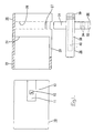
- Figure 1 is a plan cross-sectional view of a first embodiment of the present invention showing a connector in a disassembled state.
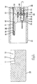
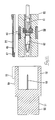
- Figures 2 is a cross-sectional view showing male and female housings.
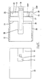
- Figure 3 is a plan cross-sectional view showing a retainer of the male housing located in a semi-retaining position.
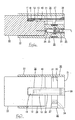
- Figure 4 is a side cross-sectional view showing the retainer of the male housing located in the semi-retaining position.
- Figure 5 is a plan cross-sectional view showing the retainer of the male housing located in a fully-retaining position.
- Figure 6 is a side cross-sectional view showing the two housings in a correctly fitted state.
- Figure 7 is a cross-sectional view showing the two housings in the correctly fitted state.
- Figure 8 is a side cross-sectional view showing the two housings in a state whereby their fitting operation is prevented.
- Figure 9 is a plan cross-sectional view showing the two housings in a state whereby their fitting operation is prevented.
- Figure 10 is a plan view of a second embodiment of the present invention showing a retained of a female housing located in a semi-retaining position.
- Figure 11 is a side cross-sectional view showing the retainer of the female housing located in a fully-retaining position.
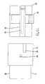
- Figure 12 is a plan view showing the retainer of the female housing located in a fully-retaining position.
- Figure 13 is a side cross-sectional view showing two housings in a correctly fitted state.
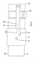
- Figure 14 is a plan view showing the two housings in the correctly fitted state.
- Figure 15 is a side cross-sectional view showing the two housings in a state whereby their fitting operation is prevented.
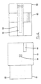
- Figure 16 is a plan view showing the two housings in a state whereby their fitting operation is prevented.
- A first embodiment of the present invention is described with the aide of Figures 1 to 9. As shown in Figures 1 and 2, the present embodiment has a female connector housing 10 that fits with a male connector housing 20. The detection of a half-inserted state of a
retainer 30 attached to themale housing 20 is performed at thismale housing 20. Fitting face sides of the twohousings - A plurality of female terminal fittings (not shown) can be housed within the
female housing 10. Agroove 11 is formed in a concave manner in an upper face of thefemale housing 10. Thisgroove 11 has a specified length and extends from approximately a central location thereof, relative to the widthwise direction, to an anterior edge thereof. Alocking arm 36 in themale housing 20 can enter thisgroove 11. The width of thegroove 11 is approximately the same as the width of thelocking arm 36. Alocking protrusion 12, which engages with thelocking arm 36, protrudes upwards from thegroove 11. A tapered face is formed on an anterior face of thelocking protrusion 12. - The
male housing 20 is provided with aterminal housing member 21 which is capable of housingmale terminal fittings 24, and ahood 22 which surrounds theterminal housing member 21. A plurality ofcavities 23, into which the maleterminal fittings 24 are inserted from the posterior, are aligned in a widthwise direction within theterminal housing member 21. Eachmale terminal fitting 24 is provided withmetal lances 25 which engage with stepped portions formed on side faces of thecavities 23. Thefemale housing 10 can be fitted into thehood 22 from the anterior side thereof, thefemale housing 10 being inserted into an anterior end of theterminal housing member 21 within a portion of thishood 22 designated as a fitting area. - A
retainer attachment groove 26 is formed at an upper face, a lower face, and an outer side face of theterminal housing member 21. A channel-shaped retainer 30 is inserted into thisretainer attachment groove 26 from the outer side. Theretainer attachment groove 26 is located at approximately the centre of the terminal housing member 21 (relative to the lengthwise direction thereof).Latching protrusions 27 protrude upwards and downwards from specified locations, in the vicinity of the outer side, of upper and lower faces of theretainer attachment groove 26. Aretainer attachment hole 28, into which a retainedmember 33 of theretainer 30 can be inserted, opens onto the outer side of theterminal housing member 21. Theretainer attachment hole 28 is formed so as to pass through, in a widthwise direction, thecavities 23 within theterminal housing member 21. Anopening 29 is formed in the side face of the outer side of thehood 22, this allowing the lockingarm 36 of theretainer 30 to pass therethrough. - The
retainer 30 is inserted from the outer side of themale housing 20 in a direction perpendicular to the fitting direction of the twohousings 10 and 20 (that is, perpendicular to the direction of insertion of the male terminal fittings 24). Theretainer 30 is provided with an upper and lower pair of supportingmembers 31 whose outer ends are joined by a joiningmember 32. An inner side face of the joiningmember 32 has the retainingmember 33 of theretainer 30 protruding therefrom in the extending direction of the supportingmembers 31. - Two
grooves retainer 30, are formed in an inner face of each of the two supportingmembers 31. When theretainer 30 is located towards the outer side, these grooves engage with the latchingprotrusions 27 provided in theretainer attachment groove 26 of theterminal housing member 31. This allows theretainer 30 to be maintained in two different positions relative to its direction of insertion into themale housing 20; a position towards the outer side, and a position at the inner side. - The retaining
member 33 is provided with a plurality of recessedholes 35. When the retainingmember 33 is in an inserted state within theretainer attachment hole 28, these recessedholes 35 join with thecavities 23. - The
retainer 30 can be maintained in a semi-retaining position (at the outer side) by virtue ofgroove 34A, and a fully-retaining position (at the inner side) by virtue ofgroove 34B and can be moved between these two positions. When theretainer 30 is in the semi-retaining position (see Figure 4), the recessedholes 35 of the retainingmember 33 are located so as to be connected with thecavities 23, this allowing the maleterminal fittings 24 to be inserted into thesecavities 23. When theretainer 30 is located in the fully-retaining position (see Figure 2), hole edges of the recessedholes 35 of the retainingmember 33 are within thecavities 23, and the maleterminal fittings 24 are retained within thesecavities 23. - As shown in Figures 1 and 2, the locking
arm 36 protrudes upwards from an upper face of theretainer 30. This lockingarm 36 is located in approximately the centre (relative to the widthwise direction) of the upper supportingmember 31 and protrudes in an anterior-posterior direction from theretainer 30, in the fitting direction of the twohousings arm 36 is formed in a see-saw shape, being provided with asupport 37 protruding upwards from the supportingmember 31, and anarm member 38 that extends in an anterior-posterior direction. Thearm member 38 can be moved resiliently up or down, with thesupport 37 serving as its centre. An operatingend 39 protrudes upwards from a posterior end of thearm member 38. The lockingarm 36 can be bent by pressing this operatingend 39. - A
concave groove 40, which has a specified width, is formed in the centre, relative to the widthwise direction, of a lower face of thearm member 38. Theconcave groove 40 is open to the posterior of thearm member 38, and a lockingclaw 41 is formed at an anterior end of the concave groove 40 (that is, at an anterior end portion of the arm member 38). As shown in Figure 5, when theretainer 30 is attached to themale housing 20 in the fully-retaining position, thearm member 38 is in alignment with thegroove 11 of thefemale housing 10. As the twohousings arm member 38 enters thisgroove 11 of thefemale housing 10, and the lockingclaw 41 engages with the lockingprotrusion 12 of the groove 11 (see Figure 6). When theretainer 30 is in the fully-retaining position, the anterior end of thearm member 38 is located at a specified distance from the anterior end of the male housing 20 (this specified distance is about one fourth of the entire length of the male housing 20). - As shown in Figure 2, the height of the
groove 11 of the female housing 10 (that is, the height of aside wall 13 surrounding the groove 11) is approximately the same as the height of a ceiling face of thehood 22, and is higher than the lockingarm 36. As a result, when theretainer 30 is located in themale housing 20 at a position towards the outer side relative to its fully-retaining position (theretainer 30 being located in, for example, the semi-retaining position), an anterior end face of the lockingarm 36 makes contact with ananterior end face 13a of the side wall 13 (see Figure 8). - The present embodiment is configured as described above. Next, the operation thereof will be described. First, the
retainer 30 is inserted from the other side into themale housing 20, this attaching theretainer 30 in the semi-retaining position (see Figures 3 and 4). In this state, the maleterminal fittings 24 are inserted into thecavities 23, then theretainer 30 is pushed into the fully-retaining position (see Figures 2 and 5). At this juncture, the maleterminal fittings 24 are retained by the retainingmember 33 of theretainer 30, this maintaining the maleterminal fittings 24 in an unremovable state. At this point, an outer face side of theretainer 30 and an outer side face of themale housing 20 form an approximately unified face. Then, the twohousings - As the
female housing 10 is inserted into the angular tubular portion of thehood 22 of themale housing 20, the lockingarm 36 that protrudes to the anterior from theterminal housing member 21 is inserted into thegroove 11. This insertion is guided by the lockingarm 36 sliding side faces of thegrooves 11. When the anterior end of the lockingarm 36 reaches the lockingprotrusion 12, a claw member of thearm member 38 rises over the lockingprotrusion 12, and the lockingarm 36 bends resiliently. When the twohousings claw 41 rises completely over the lockingprotrusion 12, the lockingarm 36 returns to its original position, and the lockingclaw 41 is located to the immediate posterior of the lockingprotrusion 12, thereby retaining mutually opposing faces of the lockingclaw 41 and the locking protrusion 12 (see Figure 6). By this means, the twohousings - In this fitted state (see Figure 7), the locking
arm 36 is located so as to be parallel with theside wall 13 of thegroove 11, the lockingarm 36 being located at the inner side relative to thisside wall 13. Consequently, if a pulling force is exerted on theretainer 30 in a direction of removal (that is, towards the outer side), the inner side face of the lockingarm 36 is retained by the side face of theside wall 13, thereby preventing theretainer 30 from leaving themale housing 20. - It is possible that, before the two
housings retainer 30 which is insufficient to push it from the semi-retaining position to the fully-retaining position, or the pushing operation may have been forgotten. In either case, theretainer 30 will be located towards the outer side relative the fully-retaining position (that is, in the semi-retaining position shown in Figure 3). If the twohousings female housing 10 has been inserted for a specified depth (this being about one fourth of the entire length of the male housing 20) into thehood 22, theanterior end face 13a of theside wall 13 of thegroove 11 will strike against the anterior end face of the locking arm 36 (see Figures 8 and 9), thereby preventing the twohousings retainer 30 has not reached the fully-retaining position. - In the embodiment described above, the locking
arm 36, which is formed as one component with theretainer 30, protrudes into the fitting area into which thefemale housing 10 is inserted. Consequently, the lockingarm 36 can make contact with thefemale housing 10. This allows one to detect the half-inserted state of theretainer 30, which is attached to themale housing 20 at a location outwards and to the posterior of the fitting area. - Furthermore, the locking
arm 36, which allows one to detect the half-inserted state of theretainer 30, also functions as a configuration for locking the twohousings - A second embodiment of the present invention is described below with the aid of Figures 10 to 16. This embodiment describes the detection of a half-inserted state of a
retainer 63 provided on afemale housing 60. Furthermore, the outer side and the inner side are with reference to Figure 10, and the upper and lower directions are with reference to Figure 11. - As shown in Figures 10 and 11, a
male housing 50 is provided with aterminal housing member 51 capable of housing maleterminal fittings 53, and a tubular-shapedhood 52 protrudes towards the anterior from theterminal housing member 51. Thefemale housing 60 can be fitted into thehood 52. A lockingprotrusion 54 protrudes upwards from the centre of an upper face of thehood 52. A regulating member 55 (to be explained) protrudes upwards from a location towards the outer side relative to the lockingprotrusion 54. - A plurality of
cavities 61, into which femaleterminal fittings 62 can be inserted, are aligned in a widthwise direction within thefemale housing 60. The configuration of theretainer 63, the configuration whereby theretainer 63 is attached to thefemale housing 60, the configuration whereby theretainer 63 retains the femaleterminal fittings 62, and the configuration of a lockingarm 64 are the same as in the first embodiment, and the functions thereof are the same. Consequently, an explanation thereof is omitted. - An
arm member 65 of the lockingarm 64, which is formed in a unified manner with theretainer 63, has a length approximately the same as the length of thefemale housing 60. When theretainer 63 is in an attached state with thefemale housing 60, an anterior end face of the lockingarm 64 forms an approximately unified face with an anterior end face of thefemale housing 60. As shown in Figure 11, asupport 66 of the lockingarm 64 has a height approximately the same as the thickness as thehood 52 of themale housing 50. When thefemale housing 60 is to be inserted into thehood 52 of themale housing 50, the lockingarm 64 is located at an upper face of thehood 52. - Now the regulating
member 55 of themale housing 50 will be explained. As shown in Figure 10, the regulatingmember 55 extends from an anterior end of thehood 52 along approximately one fourth of the entire length of themale housing 50. As shown in Figure 12, the regulatingmember 55, which is located along the widthwise direction of thehood 52, is positioned towards the outer side relative to the lockingarm 64 of the retainer 63 (thisretainer 63 being attached to thefemale housing 60 in the fully-retaining position). - The present embodiment is configured as described above. Next, the operation thereof will be described. The female
terminal fittings 62 are inserted into thecavities 61 while theretainer 63 is attached to thefemale housing 60 in the semi-retaining position (see Figure 10). Then theretainer 63 is pushed in to the fully-retaining position (see Figures 11 and 12). At this juncture, an outer circumference face of theretainer 63 forms an approximately unified face with an outer circumference face of thefemale housing 60. - Next, the
female housing 60 is fitted into thehood 52 of themale housing 50, the lockingarm 64 is inserted to the inner side of the regulatingmember 55 on the upper face of thehood 52, an inner side face of this regulatingmember 55 making sliding contact with an outer side face of the lockingarm 64 and thereby guiding the movement thereof as it is inserted. Then the lockingarm 64 bends resiliently as it rises over the lockingprotrusion 54. When the twohousings claw 67 of the lockingarm 64 rises over the lockingprotrusion 54, the lockingarm 64 returns resiliently to its original position, and the lockingclaw 67 is retained by the lockingprotrusion 54, thereby maintaining the twohousings member 55 adjoins the lockingarm 64 in a parallel manner, the regulatingmember 55 being located to the outer side thereof (see Figure 14). An outer side face of the lockingarm 64 is engaged with an inner side face of the regulatingmember 55. Consequently, even if a pulling force is exerted on theretainer 63 to move it towards the outer side, theretainer 63 will be prevented from leaving thefemale housing 60. - It is possible that the two
housings retainer 50 is located towards the outer side relative to the fully-retaining position (that it, in the semi-retaining position shown in Figure 10). In that case, as shown in Figures 15 and 16, an anterior-end face of the lockingarm 64 will strike against an anterior-end face 55a of the regulatingmember 55 immediately before thefemale housing 60 is inserted into thehood 52 of themale housing 50, thereby preventing the twohousings retainer 63 is in the semi-retaining position. - In the embodiment described above, the locking
arm 64 protrudes further towards the anterior than theretainer 63. Consequently, the half-inserted state of theretainer 63 can be detected at the stage when the fitting operation begins, and the operability of joining the connector is improved. - Furthermore, the present invention is not limited to the embodiments described above with the aid of figures. For example, the possibilities described below also lie within the technical range of the present invention. In addition, the present invention may be embodied in various other ways without deviating from the scope thereof.
- (1) In the embodiments described above, the half-inserted state is detected of a retainer that is attached to either the male or the female housing. However, the present invention is also suitable for the case whereby the half-inserted state is detected of a retainer of both the male and female housings. That is, retainers are inserted into the male and female housings respectively from opposite sides, and regulating members are provided on both housings at locations towards the outer side relative to the direction of insertion of each retainer into its housing.
- (2) In the embodiments described above, the locking arm also serves as the configuration for detecting the half-inserted state of the retainer. However, the locking arm may equally well have only a locking function, and a detecting member may be provided separately.
- (3) In the embodiments described above, the projection and channel are both rectangular. However other shapes are possible provided that the channel can regulate movement of the retainer. A taper or pointed shape is for example possible.
- (4) As described, the projection and channel are close fitting, but the channel needs to be close fitting only on the side preventing withdrawal of the retainer - the other side of the channel need not be close fitting provided insertion of the retainer is stopped by other means.
- (5) A retainer may of course be provided in either or both male and female housings.
Claims (13)
- A connector comprising two connector housings (10,20) engageable along a fitting direction, to a fully fitted condition, said connector housings (10,20) having respective terminals therein, and a retainer (30) insertable in one of said housings (20) at right angles to said fitting direction to a final position whereby terminals in said one housing (20) are retained, characterized in that said retainer (30) includes a projection (36) extending in the fitting direction towards the other housing (10), and said other housing (10) having a regulating member (13,13a) for contact with said projection (36) and adapted to prevent movement of said housings (10,20) to the fully fitted condition in the event that said retainer (30) is not in the final position.
- A connector according to claim 1 wherein in the final position of said retainer (30), and in the fully fitted condition of said housings (10,20), said regulating member (13) is at the side of said projection (36), thereby preventing withdrawal of the retainer (30) from the final position.
- A connector according to claim 2 wherein said regulating member (13,13a) is defined by a channel (11) in the exterior of said other housing.
- A connector according to claim 1 or claim 2 wherein said regulating member (13a) comprises the anterior end wall adjacent a channel (11) in the exterior of said other housing, said end wall being adapted to abut said projection (36) in the event that said retainer (30) is not in the final position.
- A connector according to claim 3 or claim 4 wherein said projection (36) and channel (11) have a corresponding shape, and wherein said projection (36) is substantially rectangular in plan, and said channel (11) is rectangular in plan.
- A connector according to claim 5 wherein said projection (36) is a close fit in said channel (11) and wherein said projection (36) is below the upper edge of said channel (11) in the fully fitted condition.
- A connector according to claim 1 wherein said regulating member comprises a protrusion (55) upstanding from said other housing.
- A connector according to any preceding claim wherein said projection (36) comprises a latching arm (36) engageable with an abutment (12,54) of said other housing (10,50) to retain said housings (10,20,50) in the fully fitted condition.
- A connector according to claim 8 wherein said latching arm (36) is bendable.
- A connector according to claim 9 wherein said retainer (30) is cruciform in plan, one arm (36) thereof being for engagement with said regulating member (13,55) and said abutment (12,54), and an opposite arm comprising an operating member (39) for bending said one arm (36).
- A connector according to any preceding claim and further including releasable retention means (27,34B) operable between said retainer (30) and said one housing (20), said retention means (27,34B) defining an insertion depth of said retainer (30) corresponding to said final position.
- A connector according to any preceding claim and further including retaining means (27,34A) operable between said retainer (30) and said one housing (20), said retaining means (27,34A) defining an insertion depth of said retainer (30) corresponding to an initial position in which the terminals in said one housing (20) are not retained.
- A connector according to any preceding claim wherein a said retainer is insertable in the other of said housings (10) and adapted to prevent movement of said housings (10,20) to the fully fitted condition in the event that the retainer of said other housing (10) is not in the final position.
Applications Claiming Priority (2)
| Application Number | Priority Date | Filing Date | Title |
|---|---|---|---|
| JP2000189794 | 2000-06-23 | ||
| JP2000189794A JP2002008763A (en) | 2000-06-23 | 2000-06-23 | connector |
Publications (1)
| Publication Number | Publication Date |
|---|---|
| EP1168518A2 true EP1168518A2 (en) | 2002-01-02 |
Family
ID=18689381
Family Applications (1)
| Application Number | Title | Priority Date | Filing Date |
|---|---|---|---|
| EP01304791A Withdrawn EP1168518A2 (en) | 2000-06-23 | 2001-05-31 | Connector |
Country Status (3)
| Country | Link |
|---|---|
| US (1) | US6450840B2 (en) |
| EP (1) | EP1168518A2 (en) |
| JP (1) | JP2002008763A (en) |
Cited By (1)
| Publication number | Priority date | Publication date | Assignee | Title |
|---|---|---|---|---|
| WO2003103100A1 (en) * | 2002-06-04 | 2003-12-11 | Robert Bosch Gmbh | Secondary locking of a plug-in connection on two planes |
Families Citing this family (10)
| Publication number | Priority date | Publication date | Assignee | Title |
|---|---|---|---|---|
| ES1044530Y (en) * | 1999-11-10 | 2000-09-01 | Mecanismos Aux Ind | LOCKING ELEMENT FOR ELECTRICAL CONNECTOR ASSEMBLY. |
| US8235895B2 (en) * | 2000-05-18 | 2012-08-07 | Commwell Research and Development Ltd. | Medical sensor kit for combination with a chair to enable measurement of diagnostic information |
| US20040260156A1 (en) | 2001-05-18 | 2004-12-23 | Commwell, Inc. | Chair and ancillary apparatus with medical diagnostic features in a remote health monitoring system |
| JP4231651B2 (en) * | 2002-03-05 | 2009-03-04 | 第一電子工業株式会社 | Electrical connector |
| DE10243256A1 (en) * | 2002-09-17 | 2004-03-25 | Daimlerchrysler Ag | Assembly for forming an electrical connector part |
| JP4636050B2 (en) * | 2007-04-27 | 2011-02-23 | 住友電装株式会社 | connector |
| JP2011100559A (en) * | 2009-11-04 | 2011-05-19 | Sumitomo Wiring Syst Ltd | Connector |
| DE102016215123A1 (en) * | 2016-08-12 | 2018-02-15 | Te Connectivity Germany Gmbh | Connection System |
| WO2019178520A1 (en) | 2018-03-16 | 2019-09-19 | Fci Usa Llc | High density electrical connectors |
| JP7904075B2 (en) * | 2022-09-14 | 2026-08-12 | 矢崎総業株式会社 | connector |
Family Cites Families (2)
| Publication number | Priority date | Publication date | Assignee | Title |
|---|---|---|---|---|
| JPH0160474U (en) | 1987-10-09 | 1989-04-17 | ||
| JP3211672B2 (en) * | 1996-07-11 | 2001-09-25 | 住友電装株式会社 | connector |
-
2000
- 2000-06-23 JP JP2000189794A patent/JP2002008763A/en active Pending
-
2001
- 2001-05-31 EP EP01304791A patent/EP1168518A2/en not_active Withdrawn
- 2001-06-06 US US09/874,207 patent/US6450840B2/en not_active Expired - Fee Related
Cited By (2)
| Publication number | Priority date | Publication date | Assignee | Title |
|---|---|---|---|---|
| WO2003103100A1 (en) * | 2002-06-04 | 2003-12-11 | Robert Bosch Gmbh | Secondary locking of a plug-in connection on two planes |
| US7234978B2 (en) | 2002-06-04 | 2007-06-26 | Robert Bosch Gmbh | Secondary locking of a plug-in connection on two planes |
Also Published As
| Publication number | Publication date |
|---|---|
| US20010055918A1 (en) | 2001-12-27 |
| US6450840B2 (en) | 2002-09-17 |
| JP2002008763A (en) | 2002-01-11 |
Similar Documents
| Publication | Publication Date | Title |
|---|---|---|
| US6439915B2 (en) | Connector | |
| US5934946A (en) | Connector | |
| EP2020706A2 (en) | A connector, connector assembly and connection method | |
| EP1143569A2 (en) | Electrical connector | |
| EP0898330A2 (en) | A connector provided with a retainer | |
| JP2001230021A (en) | connector | |
| US5910028A (en) | Connector | |
| US6450840B2 (en) | Connector with insertable retainer | |
| US6575775B2 (en) | Connector with shorting terminal | |
| EP1107382B1 (en) | Electrical connector | |
| EP1204171B1 (en) | Electrical connector | |
| EP1560297B1 (en) | Connector with retaining finger having excessive deformation prevention means | |
| US6247957B1 (en) | Connector with detection member | |
| US6443781B2 (en) | Connector | |
| US6533602B2 (en) | Divided connector | |
| US6264507B1 (en) | Terminal fitting with upstanding projection | |
| EP0999614A2 (en) | Electrical connector provided with a locking member | |
| EP1204170B1 (en) | Electrical connector | |
| JP2002190339A (en) | connector | |
| JP2005190821A (en) | Connector assembly | |
| EP1220371B1 (en) | Divided connector | |
| JPH0523455U (en) | connector | |
| US20250309578A1 (en) | Interlocking connector design for electrical connectors |
Legal Events
| Date | Code | Title | Description |
|---|---|---|---|
| PUAI | Public reference made under article 153(3) epc to a published international application that has entered the european phase |
Free format text: ORIGINAL CODE: 0009012 |
|
| STAA | Information on the status of an ep patent application or granted ep patent |
Free format text: STATUS: THE APPLICATION HAS BEEN WITHDRAWN |
|
| 17P | Request for examination filed |
Effective date: 20010615 |
|
| AK | Designated contracting states |
Kind code of ref document: A2 Designated state(s): AT BE CH CY DE DK ES FI FR GB GR IE IT LI LU MC NL PT SE TR |
|
| AX | Request for extension of the european patent |
Free format text: AL;LT;LV;MK;RO;SI |
|
| 18W | Application withdrawn |
Withdrawal date: 20011212 |