EP1168506A2 - A structure for connecting a terminal of a shielded cable - Google Patents
A structure for connecting a terminal of a shielded cable Download PDFInfo
- Publication number
- EP1168506A2 EP1168506A2 EP01114698A EP01114698A EP1168506A2 EP 1168506 A2 EP1168506 A2 EP 1168506A2 EP 01114698 A EP01114698 A EP 01114698A EP 01114698 A EP01114698 A EP 01114698A EP 1168506 A2 EP1168506 A2 EP 1168506A2
- Authority
- EP
- European Patent Office
- Prior art keywords
- connecting tube
- shielded cable
- shield layer
- caulked
- terminal
- Prior art date
- Legal status (The legal status is an assumption and is not a legal conclusion. Google has not performed a legal analysis and makes no representation as to the accuracy of the status listed.)
- Granted
Links
- 238000003780 insertion Methods 0.000 description 3
- 230000037431 insertion Effects 0.000 description 3
- 230000001681 protective effect Effects 0.000 description 3
- 230000007423 decrease Effects 0.000 description 2
- 239000002184 metal Substances 0.000 description 2
- 238000012986 modification Methods 0.000 description 2
- 230000004048 modification Effects 0.000 description 2
- 206010016275 Fear Diseases 0.000 description 1
- 239000004020 conductor Substances 0.000 description 1
Images




Classifications
-
- H—ELECTRICITY
- H01—ELECTRIC ELEMENTS
- H01R—ELECTRICALLY-CONDUCTIVE CONNECTIONS; STRUCTURAL ASSOCIATIONS OF A PLURALITY OF MUTUALLY-INSULATED ELECTRICAL CONNECTING ELEMENTS; COUPLING DEVICES; CURRENT COLLECTORS
- H01R9/00—Structural associations of a plurality of mutually-insulated electrical connecting elements, e.g. terminal strips or terminal blocks; Terminals or binding posts mounted upon a base or in a case; Bases therefor
- H01R9/03—Connectors arranged to contact a plurality of the conductors of a multiconductor cable, e.g. tapping connections
- H01R9/05—Connectors arranged to contact a plurality of the conductors of a multiconductor cable, e.g. tapping connections for coaxial cables
- H01R9/0518—Connection to outer conductor by crimping or by crimping ferrule
Definitions
- the present invention relates to a structure for connecting a shield layer of a terminal of a shielded cable to a shield wall.
- FIG. 6 Hitherto, there has been known such a kind of a terminal connecting structure illustrated in FIG. 6.
- a stepped connecting tube 3 having a front-end side portion reduced in diameter is press-fitted into and fixed in a mounting hole 2 opening in a longitudinally extending shield wall 1.
- An end portion of a shield layer 5, constituted by a braided wire, is exposed at a terminal of a shielded cable 4. Then, the exposed portion is turned up and put upon a corresponding end portion of the outer sheath 7 through an underlay C-ring 6.
- the turned-up portion 5A of the shield layer 5 is inserted into a diameter reduction portion 3A of the connecting tube 3 and fastened thereto by caulking the diameter reduction portion 3A so that the shield layer 5 is sandwiched between the portion 3A and the C-ring 6.
- the diameter reduction portion 3A of the connecting tube 3 is caulked along its entire length in the related art, a portion 8 between the diameter reduction portion 3A and a diameter enlargement portion 3B of the connecting tube 3 is formed like a bellmouth, whose diameter gradually increases from portion 3A to portion 3B at a place corresponding to a side of the turned-up end portion of the shield layer 5 (at the right end side, as viewed in FIG. 6), and the portion 8 is merely engaged to the shielded cable 4.
- the shielded cable 4 is pushed forward (that is, to the left, as viewed in this figure)
- the above engaging portion 8 becomes an engaging point so that engaging forth can be obtained.
- the engaging force is weak so that the shielded cable 4 easily comes off from the connecting tube 3.
- the front end of the connecting tube 3 is set at the same position as a position of a folded-back portion 5A of the shield layer 5, or at a position behind the folded-back portion 5A. Consequently, the folded-back portion 5A of the shield layer 5 is exposed. Thus, there are fears that the portion 5A may touch other components and may be damaged, and that when the connecting tube 3 is caulked, the shield layer 5 may be cut by the front edge of the tube 3.
- an object of the invention is to increase a fastening force to connect the shield layer to the shield wall. Further, another object of the invention is to protect the exposed portion of the shield layer.
- a structure for connecting a terminal of a shielded cable comprising:
- the connecting tube has two intermediate portions, whose diameters taper from a large diameter to a small diameter.
- a fourth aspect of the invention there is provided the structure according to any one of the first to third aspects of the invention, wherein one of the large diameter portions is larger in diameter than the other thereof.
- a fifth aspect of the invention there is provided the structure according to any one of the first to fourth aspects of the invention, wherein one of the large diameter portions has a guiding tapered portion, which is bent inwardly, at the end of the large diameter portion.
- a structure for connecting a terminal of a shielded cable comprising:
- a seventh aspect of the invention there is provided the structure according to the sixth aspect of the invention, wherein the end of the connecting tube is bent inwardly to cover with the exposed shielded cable.
- the connecting tube is caulked in such a manner as to form the two bellmouths so that the radial dimensions of the bellmouths gradually increase in opposite directions, respectively.
- the bellmouths serve as an engaging point for holding the shielded cable and thus can restrict the movement of the shielded cable. Consequently, the fastening force can be increased.
- the diameter at the front end side of the connecting tube is made to be small. This facilitates an operation of inserting the connecting tube into the shielded wall.
- the guiding tapered part leads the connecting tube into the mounting hole. Consequently, the operation of inserting the connecting tube into the mounting hole is facilitated.
- the front end portion of the connecting tube covers and protects the front end of the shield layer and the vicinity thereof, thereby preventing the front end of the shield layer from touching other components. Moreover, the shield layer is prevented from being cut by the edge of the front end portion of the connecting tube when the connecting tube is caulked.
- the front surface of the front end portion of the shield layer is covered, so that the front end portion thereof is more reliably protected.
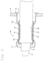
- FIG. 1 is a sectional view of a first embodiment of the invention.
- FIG. 2 is a sectional view of a second embodiment of the invention.
- FIG. 3 is a sectional view of a third embodiment of the invention.
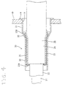
- FIG. 4 is a sectional view of a fourth embodiment of the invention.
- FIG. 5 is a sectional view of a fifth embodiment of the invention.
- FIG. 6 is a sectional view of a related art.
- Reference numeral 10 designates a shield wall formed of a metallic case of equipment and the like.
- a circular mounting hole 11 is opened at a predetermined place in the shield wall 10.
- a connecting tube 13 to be caulked is attached into the mounting hole 11.
- the connecting tube 13 is made of metal, and formed in a cylinder enabling it to be press-fitted into the mounting hole 11. More particularly, a flange 14 is formed along a rear edge of the connecting tube 13. Moreover, as indicated by chain lines in Fig. 1, a middle portion having predetermined length at a position which is a little close to the front end side in the direction of length of the tube 13 is preliminarily narrowed.
- the shielded cable 20 has a structure in which a core wire 21, an inner insulating layer 22, a shield layer 23 formed of a braided wire, and an outer sheath 24 are serially provided from a core side in this order.
- a terminal of the cable 20 the core wire 21, the inner insulating layer 22, and the shield layer 23 are exposed serially in this order.
- a terminal metal fitting (not shown) is connected to the terminal of the cable conductor 21.
- An underlay C-ring 25 is fitted onto the terminal of the outer sheath 24, while the terminal of the shield layer 23 is turned up and put on the C-ring 25.
- the dimension of the turned-up portion of the shield layer 23 is slightly larger than the length of the narrowed portion 15 of the connecting tube 13.
- the connecting tube 13 is inserted into the mounting hole 11 of the shield wall 10 from a surface side (that is, the right side, as viewed in FIG. 1).
- the connecting tube 13 is press-fitted into the mounting hole 11 in a state where the connecting tube 13 projects to the rear surface side of the shield wall 10 laterally.
- the shielded cable 20, which undergoes terminal processing by turning up the shield layer 23 partly on the C-ring 25, is inserted into the connecting tube 13 from the surface side.
- the insertion of the shielded cable 20 stops. Subsequently, a position of the connecting tube 13 corresponding to the narrowed portion 15 is caulked by using an appropriate jig while sandwiching the shield layer 23 between the C-ring 25 and a caulked portion.
- the connecting tube 13 is caulked in such a manner as to form tapering sections 17A and 17B,also known as bellmouths, which gradually increase in radial dimension, and are formed to be in opposite directions with respect to each other.
- a part of a base end portion of the front-side bellmouth 17A engages the shield layer 23, and serves as an engaging point when the cable 20 is rearwardly pulled (that is, pulled to the right side, as viewed in FIG. 1).
- a part of a base end portion of the rear-side bellmouth 17B engages the shield layer 23, and serves as an engaging point when the cable 20 is forwardly pushed. That is, the movement of the shielded cable 20 in both the directions of push and pull of the cable 20 is effectively prevented. In other words, the shielded cable 20 is firmly fastened to the connecting tube 13.
- FIG. 2 shows a second embodiment corresponding to a second aspect of the invention.
- the rear-end side portion is formed in such a way as to have a diameter X for enabling the rear-end side portion to be press-fitted into the mounting hole 11.
- a diameter Y of the front-end side portion is set at a value that is smaller than the diameter X of the rear-end side portion.
- the two bellmouths 17A and 17B are formed to be in opposite directions with respect to each other by caulking the connecting tube 13A so that the fastening force is increased.
- the connecting tube 13A is formed so that the diameter Y of the front-end side portion is smaller than the diameter X of the rear-end side portion, thereby facilitating the operation of inserting the connecting tube 13A into the mounting hole 11.
- FIG. 3 shows a third embodiment corresponding to a third aspect of the invention.
- the front end portion of the connecting tube 13B is obliquely and inwardly bent, and the guiding tapered portion 27, whose radial dimension gradually decreases to the front end thereof, is formed at the front end thereof.
- the remaining structure of the third embodiment is the same as the structure of the first embodiment.
- a guiding tapered portion may be provided at the front end portion of the connecting tube 13A, whose radial dimension is reduced, as exemplified in the description of the second embodiment.
- a connecting tube 30 according to the fourth embodiment is shaped so that a diameter reduction portion 33 is continuously provided in front of a press-fitted portion 31, which has a flange 14 that can be press-fitted into a mounting hole 11 bored in the shield wall 10, through the tapered portion 32 tapering off to the front.
- the structure of a shielded cable 20 is similar to that of the cable 20 according to the first embodiment.
- the diameter reduction portion 33 of the connecting tube 30 is larger in a length in the direction of the axis thereof than the turned-up shield layer 23 of the shielded cable 20.
- the turned-up shield layer 23 of the shield cable 20 When the turned-up shield layer 23 of the shield cable 20 is inserted into the connecting tube 30 during the assembly of the structure, a folded-back portion 23A of the shield layer 23 is placed more backward than the front edge of the diameter reduction portion 33. Further, the turned-up end portion 23B of the shield layer 23 extends beyond the rear end of the diameter reduction portion 33. At that time, insertion of the layer 23 stops. In such a state, the diameter reduction portion 33 of the connecting tube 30 is caulked along its entire length and fixed to the cable 20 while the shield layer 23 is sandwiched between the C-ring 25 and the diameter reduction portion 33.
- the front end of the diameter reduction portion 33 of the connecting tube 30 is set to project beyond the folded-back portion 23A of the shield layer 23, thereby preventing the front edge of the diameter reduction portion 33 from cutting the shield layer 23 when the portion 33 is caulked. Moreover, after being caulked, the front end part of the diameter reduction portion 33 covers the periphery of the folded-back portion 23A of the shield layer 23, thereby protecting the folded-back portion 23A from hitting other components.
- FIG. 5 shows a fifth embodiment corresponding to a fifth aspect of the invention.
- the fifth embodiment is a modification of the fourth embodiment.
- the front end part of a diameter reduction portion 33 of a connecting tube 30A is obliquely and inwardly bent.
- a protective tapered portion 35 which radial dimension gradually decreases to the front thereof, is formed.
- the rest of this structure is similar to the corresponding part of the structure according to the fourth embodiment.
- the front part of the folded-back portion 23A is more reliably covered with the protective tapered portion 35.
- the protective tapered portion 35 can be utilized as a guide for inserting the connecting tube 30A into the mounting hole 11 formed in the shield wall 10.
Landscapes
- Cable Accessories (AREA)
- Coupling Device And Connection With Printed Circuit (AREA)
- Installation Of Indoor Wiring (AREA)
- Shielding Devices Or Components To Electric Or Magnetic Fields (AREA)
- Multi-Conductor Connections (AREA)
Abstract
Description
- The present invention relates to a structure for connecting a shield layer of a terminal of a shielded cable to a shield wall.
- Hitherto, there has been known such a kind of a terminal connecting structure illustrated in FIG. 6. In this structure, a stepped connecting
tube 3 having a front-end side portion reduced in diameter is press-fitted into and fixed in amounting hole 2 opening in a longitudinally extending shield wall 1. An end portion of ashield layer 5, constituted by a braided wire, is exposed at a terminal of a shieldedcable 4. Then, the exposed portion is turned up and put upon a corresponding end portion of theouter sheath 7 through an underlay C-ring 6. The turned-upportion 5A of theshield layer 5 is inserted into adiameter reduction portion 3A of the connectingtube 3 and fastened thereto by caulking thediameter reduction portion 3A so that theshield layer 5 is sandwiched between theportion 3A and the C-ring 6. - However, the
diameter reduction portion 3A of the connectingtube 3 is caulked along its entire length in the related art, aportion 8 between thediameter reduction portion 3A and adiameter enlargement portion 3B of the connectingtube 3 is formed like a bellmouth, whose diameter gradually increases fromportion 3A toportion 3B at a place corresponding to a side of the turned-up end portion of the shield layer 5 (at the right end side, as viewed in FIG. 6), and theportion 8 is merely engaged to the shieldedcable 4. Thus, when the shieldedcable 4 is pushed forward (that is, to the left, as viewed in this figure), the aboveengaging portion 8 becomes an engaging point so that engaging forth can be obtained. Whereas, when the shieldedcable 4 is pulled backwardly, the engaging force is weak so that the shieldedcable 4 easily comes off from the connectingtube 3. - Further, in the related art, the front end of the connecting
tube 3 is set at the same position as a position of a folded-back portion 5A of theshield layer 5, or at a position behind the folded-back portion 5A. Consequently, the folded-back portion 5A of theshield layer 5 is exposed. Thus, there are fears that theportion 5A may touch other components and may be damaged, and that when the connectingtube 3 is caulked, theshield layer 5 may be cut by the front edge of thetube 3. - The invention is accomplished in view of the aforementioned circumstances. Accordingly, an object of the invention is to increase a fastening force to connect the shield layer to the shield wall. Further, another object of the invention is to protect the exposed portion of the shield layer.
- To achieve the foregoing objects, according to a first aspect of the invention, there is provided a structure for connecting a terminal of a shielded cable comprising:
- a shielded cable having a shield layer exposed at the end of the shielded cable; and
- a connecting tube attached to an opening formed in a shield wall,
- wherein the connecting tube has a large diameter portion at each end and a small diameter portion; and
- the small diameter portion is caulked to be press-fitted to the shielded cable.
- According to a second aspect of the invention, there is provided the structure according to the first aspect of the invention, wherein the connecting tube has two intermediate portions, whose diameters taper from a large diameter to a small diameter.
- According to a third aspect of the invention, there is provided the structure according to the first or second aspect of the invention, wherein the end of the connecting tube covers the exposed shield layer.
- According to a fourth aspect of the invention, there is provided the structure according to any one of the first to third aspects of the invention, wherein one of the large diameter portions is larger in diameter than the other thereof.
- According to a fifth aspect of the invention, there is provided the structure according to any one of the first to fourth aspects of the invention, wherein one of the large diameter portions has a guiding tapered portion, which is bent inwardly, at the end of the large diameter portion.
- According to a sixth aspect of the invention, there is provided a structure for connecting a terminal of a shielded cable comprising:
- a shielded cable having a shield layer exposed at the end of the shielded cable; and
- a connecting tube attached to an opening formed in a shield wall,
- wherein the end of the connecting tube covers the exposed shielded cable; and
- the connecting tube is caulked to be press-fitted to the shielded cable.
- According to a seventh aspect of the invention, there is provided the structure according to the sixth aspect of the invention, wherein the end of the connecting tube is bent inwardly to cover with the exposed shielded cable.
- According to the first aspect of the invention, the connecting tube is caulked in such a manner as to form the two bellmouths so that the radial dimensions of the bellmouths gradually increase in opposite directions, respectively. Thus, in the case of moving the shielded cable in both the forward and backward directions, the bellmouths serve as an engaging point for holding the shielded cable and thus can restrict the movement of the shielded cable. Consequently, the fastening force can be increased.
- According to the fourth aspect of the invention, the diameter at the front end side of the connecting tube is made to be small. This facilitates an operation of inserting the connecting tube into the shielded wall.
- According to the fifth aspect of the invention, the guiding tapered part leads the connecting tube into the mounting hole. Consequently, the operation of inserting the connecting tube into the mounting hole is facilitated.
- According to the third or sixth aspect of the invention, the front end portion of the connecting tube covers and protects the front end of the shield layer and the vicinity thereof, thereby preventing the front end of the shield layer from touching other components. Moreover, the shield layer is prevented from being cut by the edge of the front end portion of the connecting tube when the connecting tube is caulked.
- According to the seventh aspect of the invention, the front surface of the front end portion of the shield layer is covered, so that the front end portion thereof is more reliably protected.
- FIG. 1 is a sectional view of a first embodiment of the invention.
- FIG. 2 is a sectional view of a second embodiment of the invention.
- FIG. 3 is a sectional view of a third embodiment of the invention.
- FIG. 4 is a sectional view of a fourth embodiment of the invention.
- FIG. 5 is a sectional view of a fifth embodiment of the invention.
- FIG. 6 is a sectional view of a related art.
- Hereinafter, various embodiments of the invention are described with reference to the accompanying drawings.
- A first embodiment corresponding to a first aspect of the invention is described with reference to FIG. 1.
Reference numeral 10 designates a shield wall formed of a metallic case of equipment and the like. Acircular mounting hole 11 is opened at a predetermined place in theshield wall 10. - A connecting
tube 13 to be caulked is attached into themounting hole 11. The connectingtube 13 is made of metal, and formed in a cylinder enabling it to be press-fitted into themounting hole 11. More particularly, aflange 14 is formed along a rear edge of the connectingtube 13. Moreover, as indicated by chain lines in Fig. 1, a middle portion having predetermined length at a position which is a little close to the front end side in the direction of length of thetube 13 is preliminarily narrowed. - The shielded
cable 20 has a structure in which acore wire 21, an inner insulatinglayer 22, ashield layer 23 formed of a braided wire, and anouter sheath 24 are serially provided from a core side in this order. At a terminal of thecable 20, thecore wire 21, the innerinsulating layer 22, and theshield layer 23 are exposed serially in this order. A terminal metal fitting (not shown) is connected to the terminal of thecable conductor 21. - An underlay C-
ring 25 is fitted onto the terminal of theouter sheath 24, while the terminal of theshield layer 23 is turned up and put on the C-ring 25. Incidentally, the dimension of the turned-up portion of theshield layer 23 is slightly larger than the length of the narrowedportion 15 of the connectingtube 13. - Assembly of this structure is performed as follows. First, the connecting
tube 13 is inserted into the mountinghole 11 of theshield wall 10 from a surface side (that is, the right side, as viewed in FIG. 1). When theflange 14 touches an opening edge on a surface of the mountinghole 11, the connectingtube 13 is press-fitted into the mountinghole 11 in a state where the connectingtube 13 projects to the rear surface side of theshield wall 10 laterally. - Subsequently, the shielded
cable 20, which undergoes terminal processing by turning up theshield layer 23 partly on the C-ring 25, is inserted into the connectingtube 13 from the surface side. - As the turned-up
shield layer 23 of the shieldedcable 20 just enters the inside of the narrowedportion 15 of the connectingtube 13, the insertion of the shieldedcable 20 stops. Subsequently, a position of the connectingtube 13 corresponding to the narrowedportion 15 is caulked by using an appropriate jig while sandwiching theshield layer 23 between the C-ring 25 and a caulked portion. - At that time, the connecting
tube 13 is caulked in such a manner as to form taperingsections - Consequently, a part of a base end portion of the front-
side bellmouth 17A, engages theshield layer 23, and serves as an engaging point when thecable 20 is rearwardly pulled (that is, pulled to the right side, as viewed in FIG. 1). Further, a part of a base end portion of the rear-side bellmouth 17B, engages theshield layer 23, and serves as an engaging point when thecable 20 is forwardly pushed. That is, the movement of the shieldedcable 20 in both the directions of push and pull of thecable 20 is effectively prevented. In other words, the shieldedcable 20 is firmly fastened to the connectingtube 13. - FIG. 2 shows a second embodiment corresponding to a second aspect of the invention. In a connecting
tube 13A of the second embodiment having a rear-end side portion and a front-end side portion that sandwich the caulkedportion 16 therebetween, the rear-end side portion is formed in such a way as to have a diameter X for enabling the rear-end side portion to be press-fitted into the mountinghole 11. Whereas, a diameter Y of the front-end side portion is set at a value that is smaller than the diameter X of the rear-end side portion. - The rest of the structure is similar to the corresponding parts of the first embodiment. In Figure 2, like reference numerals designate like parts of the first embodiment, which have the same function. Thus, the repetition of the description of such parts is omitted.
- In the second embodiment, the two
bellmouths tube 13A so that the fastening force is increased. In addition, the connectingtube 13A is formed so that the diameter Y of the front-end side portion is smaller than the diameter X of the rear-end side portion, thereby facilitating the operation of inserting the connectingtube 13A into the mountinghole 11. - FIG. 3 shows a third embodiment corresponding to a third aspect of the invention. In the third embodiment, comparing with the first embodiment, the front end portion of the connecting
tube 13B is obliquely and inwardly bent, and the guiding taperedportion 27, whose radial dimension gradually decreases to the front end thereof, is formed at the front end thereof. The remaining structure of the third embodiment is the same as the structure of the first embodiment. - In the third embodiment, even when misalignment of core occurs during insertion of the connecting
tube 13B into the mountinghole 11, alignment therebetween is automatically performed by touching the opening edge of the mountinghole 11 with the guiding taperedportion 27. Thus, the connectingtube 13B is inserted into the mountinghole 11. Consequently, the operation of inserting the connectingtube 13B into the mountinghole 11 is smoothly and easily performed. - Incidentally, a guiding tapered portion may be provided at the front end portion of the connecting
tube 13A, whose radial dimension is reduced, as exemplified in the description of the second embodiment. - Next, a fourth embodiment corresponding to a fourth aspect of the invention is described hereinbelow with reference to FIG. 4.
- A connecting
tube 30 according to the fourth embodiment is shaped so that adiameter reduction portion 33 is continuously provided in front of a press-fittedportion 31, which has aflange 14 that can be press-fitted into a mountinghole 11 bored in theshield wall 10, through the taperedportion 32 tapering off to the front. Meanwhile, the structure of a shieldedcable 20 is similar to that of thecable 20 according to the first embodiment. Particularly, thediameter reduction portion 33 of the connectingtube 30 is larger in a length in the direction of the axis thereof than the turned-upshield layer 23 of the shieldedcable 20. - When the turned-up
shield layer 23 of theshield cable 20 is inserted into the connectingtube 30 during the assembly of the structure, a folded-back portion 23A of theshield layer 23 is placed more backward than the front edge of thediameter reduction portion 33. Further, the turned-upend portion 23B of theshield layer 23 extends beyond the rear end of thediameter reduction portion 33. At that time, insertion of thelayer 23 stops. In such a state, thediameter reduction portion 33 of the connectingtube 30 is caulked along its entire length and fixed to thecable 20 while theshield layer 23 is sandwiched between the C-ring 25 and thediameter reduction portion 33. - In this embodiment, the front end of the
diameter reduction portion 33 of the connectingtube 30 is set to project beyond the folded-back portion 23A of theshield layer 23, thereby preventing the front edge of thediameter reduction portion 33 from cutting theshield layer 23 when theportion 33 is caulked. Moreover, after being caulked, the front end part of thediameter reduction portion 33 covers the periphery of the folded-back portion 23A of theshield layer 23, thereby protecting the folded-back portion 23A from hitting other components. - FIG. 5 shows a fifth embodiment corresponding to a fifth aspect of the invention. The fifth embodiment is a modification of the fourth embodiment. The front end part of a
diameter reduction portion 33 of a connectingtube 30A is obliquely and inwardly bent. Moreover, a protective taperedportion 35,whose radial dimension gradually decreases to the front thereof, is formed. The rest of this structure is similar to the corresponding part of the structure according to the fourth embodiment. - In the fifth embodiment, the front part of the folded-
back portion 23A is more reliably covered with the protective taperedportion 35. - Incidentally, the protective tapered
portion 35 can be utilized as a guide for inserting the connectingtube 30A into the mountinghole 11 formed in theshield wall 10. - The invention is not limited to the embodiments described in the foregoing description and the accompanying drawings. Various modifications can be made therein without departing from the gist thereof.
Claims (7)
- A structure for connecting a terminal of a shielded cable, comprising:a shielded cable having a shield layer exposed at an end of the shielded cable;a shield wall defining an opening; anda connecting tube attached to the opening defined in the shield wall, the connecting tube having two large diameter portions at both ends and a small diameter portion, the small diameter portion being caulked to be press-fitted to the shielded cable.
- The structure according to claim 1, wherein the connecting tube has two intermediate tapering portions, whose diameters taper from the large diameter to the small diameter.
- The structure according to claim 1, wherein the end of the connecting tube covers the exposed shield layer.
- The structure according to claim 1, wherein one of the large diameter portions is larger in diameter than the other thereof.
- The structure according to claim 1, wherein one of the large diameter portions has a guiding tapered portion, which is bent inwardly, at an end of the large diameter portion.
- A structure for connecting a terminal of a shielded cable, comprising:a shielded cable having a shield layer exposed at an end of the shielded cable;a shield wall defining an opening; anda connecting tube attached to the opening defined in a shield wall,an end of the connecting tube covers the exposed shielded cable; andthe connecting tube being caulked to be press-fitted to the shielded cable.
- The structure according to claim 6, wherein the end of the connecting tube is bent inwardly to cover the exposed shielded cable.
Applications Claiming Priority (2)
| Application Number | Priority Date | Filing Date | Title |
|---|---|---|---|
| JP2000184701A JP3660563B2 (en) | 2000-06-20 | 2000-06-20 | Shield wire terminal connection structure |
| JP2000184701 | 2000-06-20 |
Publications (3)
| Publication Number | Publication Date |
|---|---|
| EP1168506A2 true EP1168506A2 (en) | 2002-01-02 |
| EP1168506A3 EP1168506A3 (en) | 2003-10-15 |
| EP1168506B1 EP1168506B1 (en) | 2005-10-12 |
Family
ID=18685114
Family Applications (1)
| Application Number | Title | Priority Date | Filing Date |
|---|---|---|---|
| EP01114698A Expired - Lifetime EP1168506B1 (en) | 2000-06-20 | 2001-06-19 | A structure for connecting a terminal of a shielded cable |
Country Status (4)
| Country | Link |
|---|---|
| US (1) | US6530789B2 (en) |
| EP (1) | EP1168506B1 (en) |
| JP (1) | JP3660563B2 (en) |
| DE (1) | DE60113924T2 (en) |
Cited By (6)
| Publication number | Priority date | Publication date | Assignee | Title |
|---|---|---|---|---|
| GB2380333B (en) * | 2001-07-24 | 2005-09-28 | Hewlett Packard Co | Cable retention system |
| EP1504501A4 (en) * | 2002-05-10 | 2006-12-13 | Framatome Connectors Int | Electrical cable strain relief and electrical closure |
| WO2010112518A1 (en) * | 2009-04-03 | 2010-10-07 | Kostal Kontakt Systeme Gmbh | Plug-in connector for connecting to a coaxial cable |
| EP2530785A1 (en) * | 2011-06-01 | 2012-12-05 | Amphenol-tuchel Electronics GmbH | Cable tension release and connector with cable tension release |
| DE102007047436B4 (en) * | 2007-10-04 | 2014-05-22 | Lisa Dräxlmaier GmbH | Crimping with center recess |
| EP3021420B1 (en) * | 2014-11-12 | 2017-01-11 | MD Elektronik GmbH | Multi-core shielded cable and method for producing such a cable |
Families Citing this family (26)
| Publication number | Priority date | Publication date | Assignee | Title |
|---|---|---|---|---|
| DE10259803B3 (en) * | 2002-12-19 | 2004-05-13 | Kathrein-Werke Kg | Electrical termination connection for outer conductor of coaxial cable has plug part with 2 plug sections fitting into housing wall opening with 2 reception sections |
| JP4377727B2 (en) * | 2004-03-25 | 2009-12-02 | 株式会社オートネットワーク技術研究所 | Shield connector |
| US7179117B2 (en) * | 2005-04-28 | 2007-02-20 | Hon Hai Precision Ind. Co., Ltd | Cable assembly with unique strain relief means |
| US20060260098A1 (en) * | 2005-05-18 | 2006-11-23 | Brown Michelle J | Weight for Hand-Held Tools Such as Writing Instruments |
| US7377811B2 (en) * | 2006-08-29 | 2008-05-27 | International Business Machines Corporation | Method and apparatus for associating a cable with an electronic device and improving electromagnetic compatability shielding between the cable and the electronic device |
| JP2010061891A (en) * | 2008-09-02 | 2010-03-18 | Hitachi Cable Ltd | Connector |
| JP5093048B2 (en) * | 2008-10-24 | 2012-12-05 | 株式会社豊田自動織機 | Cable fixing structure |
| JP5622307B2 (en) * | 2010-07-05 | 2014-11-12 | 矢崎総業株式会社 | Shield connector |
| CN102570361B (en) * | 2011-12-15 | 2015-05-13 | 平高集团有限公司 | Ultrahigh voltage direct current wall bushing and shielding structure thereof |
| JP6234034B2 (en) * | 2013-02-20 | 2017-11-22 | 矢崎総業株式会社 | Shield connector structure |
| DE102013011874A1 (en) * | 2013-07-17 | 2015-01-22 | Leoni Bordnetz-Systeme Gmbh | Electric power distributor for an electric or hybrid vehicle and distributor housing for such a power distributor |
| JP6168416B2 (en) * | 2014-05-28 | 2017-07-26 | 株式会社オートネットワーク技術研究所 | Shielded wire with terminal bracket |
| JP6575340B2 (en) * | 2015-12-09 | 2019-09-18 | 住友電装株式会社 | connector |
| JP6387059B2 (en) * | 2016-09-16 | 2018-09-05 | 矢崎総業株式会社 | Terminal fitting fixing structure and wire harness |
| DE102017006767B4 (en) * | 2017-07-15 | 2019-10-02 | Rosenberger Hochfrequenztechnik Gmbh & Co. Kg | CONNECTOR ARRANGEMENT |
| DE102017217476A1 (en) * | 2017-09-29 | 2019-04-04 | Te Connectivity Germany Gmbh | Support sleeve for an electric cable |
| JP6955219B2 (en) * | 2018-03-30 | 2021-10-27 | 住友電装株式会社 | Wire harness |
| CN111490411B (en) * | 2019-01-28 | 2025-03-18 | 新海洋精密组件(江西)有限公司 | Cable connector assembly and assembly method thereof |
| DE102019108886A1 (en) * | 2019-04-04 | 2020-10-08 | Rosenberger Hochfrequenztechnik Gmbh & Co. Kg | Pre-assembled electrical cable, connector arrangement, as well as method and device for assembling an electrical cable |
| US10756471B1 (en) * | 2019-06-04 | 2020-08-25 | Te Connectivity Corporation | Shield grounding electrical connectors |
| JP7515155B2 (en) * | 2020-05-29 | 2024-07-12 | 白山商事株式会社 | Crimp connection structure and crimp connection method |
| JP7435338B2 (en) * | 2020-07-27 | 2024-02-21 | 住友電装株式会社 | Terminal structure and sleeve of shielded wire |
| DE102020120662B3 (en) * | 2020-08-05 | 2021-09-02 | Md Elektronik Gmbh | Method and device for processing a cable end and correspondingly processed cable |
| CN112952479A (en) * | 2021-02-25 | 2021-06-11 | 上海毕科电子有限公司 | Airtight coupling assembly |
| JP7786279B2 (en) * | 2022-03-29 | 2025-12-16 | 住友電装株式会社 | Wire harness |
| TWI827100B (en) * | 2022-04-11 | 2023-12-21 | 益登科技股份有限公司 | Coaxial cable and signal transmission assembly thereof |
Family Cites Families (18)
| Publication number | Priority date | Publication date | Assignee | Title |
|---|---|---|---|---|
| US3539709A (en) * | 1968-11-04 | 1970-11-10 | Itt | Sealing crimp ring for coaxial connector |
| DE1807951A1 (en) * | 1968-11-08 | 1971-06-16 | Kings Electronics Co Inc | Cable connection terminal |
| US4116521A (en) * | 1976-10-12 | 1978-09-26 | Amp Incorporated | Miniature universal connector module |
| US4070751A (en) * | 1977-01-12 | 1978-01-31 | Amp Incorporated | Method of making a coaxial connector |
| US4614398A (en) * | 1984-12-21 | 1986-09-30 | Simmonds Precision | Shielded cable terminal connection |
| US4898173A (en) * | 1988-04-22 | 1990-02-06 | Medtronic, Inc. | In-line pacemaker connector system |
| JPH01177883U (en) * | 1988-06-04 | 1989-12-19 | ||
| US4963104A (en) * | 1989-05-01 | 1990-10-16 | Spark Innovations, Inc. | Shielded connector assembly |
| DE4226904C2 (en) * | 1992-08-14 | 1995-06-08 | Framatome Connectors Deutschla | Crimp sleeve |
| US5460544A (en) * | 1993-05-26 | 1995-10-24 | Yazaki Corporation | Electro-magnetically shielded connector |
| JP2868973B2 (en) | 1993-06-08 | 1999-03-10 | 矢崎総業株式会社 | Shield connector |
| DE19523795C1 (en) * | 1995-06-29 | 1996-12-19 | Siemens Ag | Cable gland for screened switch cable |
| DE29515027U1 (en) * | 1995-09-19 | 1997-01-30 | Siemens AG, 80333 München | Electrical cable with cable shield |
| US5860833A (en) * | 1997-05-01 | 1999-01-19 | Trompeter Electronics, Inc. | Electrical connector having a probe positionable between a pair of spaced positions |
| EP0920102B1 (en) * | 1997-11-28 | 2002-03-06 | Nexans | Outer protection with shield-break for high-voltage cable joint |
| JP3797585B2 (en) * | 1998-08-11 | 2006-07-19 | 矢崎総業株式会社 | Shield connector |
| US6210223B1 (en) * | 1998-11-19 | 2001-04-03 | Sumitomo Wiring Systems, Ltd. | Shielded connector, a set of shielded connectors and method for connecting a shielded connector with a shielded cable |
| US6261108B1 (en) * | 1999-04-15 | 2001-07-17 | Harness System Technologies Research, Ltd. | Shield connector |
-
2000
- 2000-06-20 JP JP2000184701A patent/JP3660563B2/en not_active Expired - Fee Related
-
2001
- 2001-05-23 US US09/862,508 patent/US6530789B2/en not_active Expired - Fee Related
- 2001-06-19 DE DE60113924T patent/DE60113924T2/en not_active Expired - Lifetime
- 2001-06-19 EP EP01114698A patent/EP1168506B1/en not_active Expired - Lifetime
Cited By (8)
| Publication number | Priority date | Publication date | Assignee | Title |
|---|---|---|---|---|
| GB2380333B (en) * | 2001-07-24 | 2005-09-28 | Hewlett Packard Co | Cable retention system |
| EP1504501A4 (en) * | 2002-05-10 | 2006-12-13 | Framatome Connectors Int | Electrical cable strain relief and electrical closure |
| DE102007047436B4 (en) * | 2007-10-04 | 2014-05-22 | Lisa Dräxlmaier GmbH | Crimping with center recess |
| WO2010112518A1 (en) * | 2009-04-03 | 2010-10-07 | Kostal Kontakt Systeme Gmbh | Plug-in connector for connecting to a coaxial cable |
| US8323055B2 (en) | 2009-04-03 | 2012-12-04 | Kostal Kontakt Systeme Gmbh | Plug-in connector for connecting to a coaxial cable |
| EP2530785A1 (en) * | 2011-06-01 | 2012-12-05 | Amphenol-tuchel Electronics GmbH | Cable tension release and connector with cable tension release |
| EP3021420B1 (en) * | 2014-11-12 | 2017-01-11 | MD Elektronik GmbH | Multi-core shielded cable and method for producing such a cable |
| US9601875B2 (en) | 2014-11-12 | 2017-03-21 | Md Elektronik Gmbh | Multi-wire shielded cable and method for manufacturing such a cable |
Also Published As
| Publication number | Publication date |
|---|---|
| US20010053633A1 (en) | 2001-12-20 |
| EP1168506B1 (en) | 2005-10-12 |
| EP1168506A3 (en) | 2003-10-15 |
| JP3660563B2 (en) | 2005-06-15 |
| US6530789B2 (en) | 2003-03-11 |
| JP2002010469A (en) | 2002-01-11 |
| DE60113924T2 (en) | 2006-07-27 |
| DE60113924D1 (en) | 2006-02-23 |
Similar Documents
| Publication | Publication Date | Title |
|---|---|---|
| US6530789B2 (en) | Structure for connecting terminal of shielded cable | |
| US6808417B2 (en) | Coaxial connector | |
| US5362251A (en) | Solderless coaxial connector plug | |
| EP0817316B1 (en) | Coaxial cable connector | |
| US20220255273A1 (en) | Cable Connector Assembly | |
| CN100481651C (en) | Manufacturing method of shielded wire harness and shielded wire harness and shielded joint | |
| EP0701307A1 (en) | An elastic part holder for use in an elastic part mounting apparatus | |
| US5389013A (en) | Electrical terminal with means to avoid locking lance damage and entanglement | |
| EP3535810B1 (en) | Connector for a coaxial cable | |
| EP1791222B1 (en) | A resilient plug and a watertight connector | |
| CN115552742A (en) | Sleeve-to-coaxial cable mounting device, sleeve-to-coaxial cable mounting method, and shield conductive path | |
| CN110073551B (en) | Strut-free automatic clamping connector for coaxial cable | |
| US7044795B2 (en) | Miniature, shielded electrical connector with strain relief | |
| EP2602889B1 (en) | Wire fixing member and wire fixing method | |
| US20240313482A1 (en) | Shielded electrically conductive path | |
| JP2004319196A (en) | Shield connection structure | |
| US7402073B2 (en) | Cable connector and method of connecting a cable with a cable connector | |
| US6098276A (en) | Contact front extraction tool | |
| JPH07201383A (en) | Shield wire terminal connection structure | |
| US6183303B1 (en) | Shielded cable end-processing construction | |
| US20170062967A1 (en) | Contact element | |
| US20220200197A1 (en) | Connection between a reinforced harness and an electrical component | |
| JP2005174767A (en) | End processing method for shielded wire | |
| JP4234489B2 (en) | Cable device | |
| JP3362837B2 (en) | Barrel structure |
Legal Events
| Date | Code | Title | Description |
|---|---|---|---|
| PUAI | Public reference made under article 153(3) epc to a published international application that has entered the european phase |
Free format text: ORIGINAL CODE: 0009012 |
|
| AK | Designated contracting states |
Kind code of ref document: A2 Designated state(s): AT BE CH CY DE DK ES FI FR GB GR IE IT LI LU MC NL PT SE TR |
|
| AX | Request for extension of the european patent |
Free format text: AL;LT;LV;MK;RO;SI |
|
| PUAL | Search report despatched |
Free format text: ORIGINAL CODE: 0009013 |
|
| AK | Designated contracting states |
Kind code of ref document: A3 Designated state(s): AT BE CH CY DE DK ES FI FR GB GR IE IT LI LU MC NL PT SE TR |
|
| AX | Request for extension of the european patent |
Extension state: AL LT LV MK RO SI |
|
| RIC1 | Information provided on ipc code assigned before grant |
Ipc: 7H 01R 9/03 B Ipc: 7H 01R 9/05 A |
|
| 17P | Request for examination filed |
Effective date: 20031202 |
|
| 17Q | First examination report despatched |
Effective date: 20040317 |
|
| AKX | Designation fees paid |
Designated state(s): DE FR |
|
| GRAP | Despatch of communication of intention to grant a patent |
Free format text: ORIGINAL CODE: EPIDOSNIGR1 |
|
| GRAS | Grant fee paid |
Free format text: ORIGINAL CODE: EPIDOSNIGR3 |
|
| GRAA | (expected) grant |
Free format text: ORIGINAL CODE: 0009210 |
|
| AK | Designated contracting states |
Kind code of ref document: B1 Designated state(s): DE FR |
|
| REF | Corresponds to: |
Ref document number: 60113924 Country of ref document: DE Date of ref document: 20060223 Kind code of ref document: P |
|
| PLBE | No opposition filed within time limit |
Free format text: ORIGINAL CODE: 0009261 |
|
| STAA | Information on the status of an ep patent application or granted ep patent |
Free format text: STATUS: NO OPPOSITION FILED WITHIN TIME LIMIT |
|
| 26N | No opposition filed |
Effective date: 20060713 |
|
| PG25 | Lapsed in a contracting state [announced via postgrant information from national office to epo] |
Ref country code: FR Free format text: LAPSE BECAUSE OF FAILURE TO SUBMIT A TRANSLATION OF THE DESCRIPTION OR TO PAY THE FEE WITHIN THE PRESCRIBED TIME-LIMIT Effective date: 20061020 |
|
| EN | Fr: translation not filed | ||
| PG25 | Lapsed in a contracting state [announced via postgrant information from national office to epo] |
Ref country code: FR Free format text: LAPSE BECAUSE OF FAILURE TO SUBMIT A TRANSLATION OF THE DESCRIPTION OR TO PAY THE FEE WITHIN THE PRESCRIBED TIME-LIMIT Effective date: 20051012 |
|
| PGFP | Annual fee paid to national office [announced via postgrant information from national office to epo] |
Ref country code: DE Payment date: 20120613 Year of fee payment: 12 |
|
| REG | Reference to a national code |
Ref country code: DE Ref legal event code: R119 Ref document number: 60113924 Country of ref document: DE Effective date: 20140101 |
|
| PG25 | Lapsed in a contracting state [announced via postgrant information from national office to epo] |
Ref country code: DE Free format text: LAPSE BECAUSE OF NON-PAYMENT OF DUE FEES Effective date: 20140101 |