EP1168497A2 - Limited field of view antenna for space borne applications - Google Patents
Limited field of view antenna for space borne applications Download PDFInfo
- Publication number
- EP1168497A2 EP1168497A2 EP00128643A EP00128643A EP1168497A2 EP 1168497 A2 EP1168497 A2 EP 1168497A2 EP 00128643 A EP00128643 A EP 00128643A EP 00128643 A EP00128643 A EP 00128643A EP 1168497 A2 EP1168497 A2 EP 1168497A2
- Authority
- EP
- European Patent Office
- Prior art keywords
- array
- feed
- reflector
- feed elements
- elements
- Prior art date
- Legal status (The legal status is an assumption and is not a legal conclusion. Google has not performed a legal analysis and makes no representation as to the accuracy of the status listed.)
- Granted
Links
Images






Classifications
-
- H—ELECTRICITY
- H01—ELECTRIC ELEMENTS
- H01Q—ANTENNAS, i.e. RADIO AERIALS
- H01Q15/00—Devices for reflection, refraction, diffraction or polarisation of waves radiated from an antenna, e.g. quasi-optical devices
- H01Q15/14—Reflecting surfaces; Equivalent structures
- H01Q15/147—Reflecting surfaces; Equivalent structures provided with means for controlling or monitoring the shape of the reflecting surface
-
- H—ELECTRICITY
- H01—ELECTRIC ELEMENTS
- H01Q—ANTENNAS, i.e. RADIO AERIALS
- H01Q1/00—Details of, or arrangements associated with, antennas
- H01Q1/27—Adaptation for use in or on movable bodies
- H01Q1/28—Adaptation for use in or on aircraft, missiles, satellites, or balloons
- H01Q1/288—Satellite antennas
-
- H—ELECTRICITY
- H01—ELECTRIC ELEMENTS
- H01Q—ANTENNAS, i.e. RADIO AERIALS
- H01Q15/00—Devices for reflection, refraction, diffraction or polarisation of waves radiated from an antenna, e.g. quasi-optical devices
- H01Q15/14—Reflecting surfaces; Equivalent structures
- H01Q15/16—Reflecting surfaces; Equivalent structures curved in two dimensions [2D], e.g. paraboloidal
- H01Q15/168—Mesh reflectors mounted on a non-collapsible frame
-
- H—ELECTRICITY
- H01—ELECTRIC ELEMENTS
- H01Q—ANTENNAS, i.e. RADIO AERIALS
- H01Q19/00—Combinations of primary active antenna elements and units with secondary devices, e.g. with quasi-optical devices, for giving the antenna a desired directional characteristic
- H01Q19/10—Combinations of primary active antenna elements and units with secondary devices, e.g. with quasi-optical devices, for giving the antenna a desired directional characteristic using reflecting surfaces
- H01Q19/12—Combinations of primary active antenna elements and units with secondary devices, e.g. with quasi-optical devices, for giving the antenna a desired directional characteristic using reflecting surfaces wherein the surfaces are concave
- H01Q19/13—Combinations of primary active antenna elements and units with secondary devices, e.g. with quasi-optical devices, for giving the antenna a desired directional characteristic using reflecting surfaces wherein the surfaces are concave the primary radiating source being a single radiating element, e.g. a dipole, a slot, a waveguide termination
-
- H—ELECTRICITY
- H01—ELECTRIC ELEMENTS
- H01Q—ANTENNAS, i.e. RADIO AERIALS
- H01Q19/00—Combinations of primary active antenna elements and units with secondary devices, e.g. with quasi-optical devices, for giving the antenna a desired directional characteristic
- H01Q19/10—Combinations of primary active antenna elements and units with secondary devices, e.g. with quasi-optical devices, for giving the antenna a desired directional characteristic using reflecting surfaces
- H01Q19/12—Combinations of primary active antenna elements and units with secondary devices, e.g. with quasi-optical devices, for giving the antenna a desired directional characteristic using reflecting surfaces wherein the surfaces are concave
- H01Q19/13—Combinations of primary active antenna elements and units with secondary devices, e.g. with quasi-optical devices, for giving the antenna a desired directional characteristic using reflecting surfaces wherein the surfaces are concave the primary radiating source being a single radiating element, e.g. a dipole, a slot, a waveguide termination
- H01Q19/132—Horn reflector antennas; Off-set feeding
-
- H—ELECTRICITY
- H01—ELECTRIC ELEMENTS
- H01Q—ANTENNAS, i.e. RADIO AERIALS
- H01Q19/00—Combinations of primary active antenna elements and units with secondary devices, e.g. with quasi-optical devices, for giving the antenna a desired directional characteristic
- H01Q19/10—Combinations of primary active antenna elements and units with secondary devices, e.g. with quasi-optical devices, for giving the antenna a desired directional characteristic using reflecting surfaces
- H01Q19/12—Combinations of primary active antenna elements and units with secondary devices, e.g. with quasi-optical devices, for giving the antenna a desired directional characteristic using reflecting surfaces wherein the surfaces are concave
- H01Q19/17—Combinations of primary active antenna elements and units with secondary devices, e.g. with quasi-optical devices, for giving the antenna a desired directional characteristic using reflecting surfaces wherein the surfaces are concave the primary radiating source comprising two or more radiating elements
-
- H—ELECTRICITY
- H01—ELECTRIC ELEMENTS
- H01Q—ANTENNAS, i.e. RADIO AERIALS
- H01Q21/00—Antenna arrays or systems
- H01Q21/06—Arrays of individually energised antenna units similarly polarised and spaced apart
-
- H—ELECTRICITY
- H01—ELECTRIC ELEMENTS
- H01Q—ANTENNAS, i.e. RADIO AERIALS
- H01Q21/00—Antenna arrays or systems
- H01Q21/06—Arrays of individually energised antenna units similarly polarised and spaced apart
- H01Q21/20—Arrays of individually energised antenna units similarly polarised and spaced apart the units being spaced along or adjacent to a curvilinear path
Definitions
- This invention relates generally to antennas used for space applications and more particularly to a hybrid parabolic reflector phased array antenna which is stowed in a collapsed state for launch and thereafter deployed to form a relatively large reflector type antenna when in orbit.
- large scanning antennas use parabolic reflectors with clusters of elements at and near the focal point to scan the beam.
- a large group of elements are used to transmit and receive.
- phase-only control is preferred, while on receive both phase and amplitude controls are used.
- amplitude is uniform while in receive it is normally tapered.
- the feed array is typically displaced forward of the focal point; however, this increases the size of the feed rapidly, with commensurate increase in blockage loss.
- Apertures comprised of a plurality of reflector super elements, all having feed array generating respective antenna patterns, steer a composite beam pattern near the desired direction.
- phase or time delay between elements is then used to fine steer the antenna.
- grating lobes are formed, which is the classic problem of using a large element in a phased array.
- the present invention is directed to a hybrid parabolic reflector phased array antenna system which is stowable in a rocket and is deployable in space.
- the antenna includes a large torus which acts as a support structure for a plurality of small reflector cells called super elements, each including its own reflector and an array of feed elements.
- the torus supports a stretched reflector mesh and matching back-up catanary wires that provide a mechanism for pulling the reflector surface of the cells down to an exact paraboloid.
- a set of rigid corner posts for stretching the mesh fabric for forming multiple reflectors is also provided.
- the torus is also used to support individual super element feed arrays for each reflector.
- the super elements incrementally scan the beam by group selection of feed elements in each feed array with time delay phase control being used to steer the array factor so as to achieve fine steering.
- Each of the super elements scans incrementally with a selected group of feed elements varying between seven and twelve, which are varied in position relative to the focal axis of the feed array.
- the groups of feed elements are reduced in number and selected so as to steer precisely to this position, thus relieving the grating lobe problem.
- Other methods of mitigating the grating lobe problem include randomly selecting groups of elements about the optimum position, gradually shifting the selected group of elements from one position to another, randomly positioning the feed arrays about their respective focal points, and overlapping feed distributions to gradually shift the feed center and thus precisely adjusting the feed element pattern to agree with the array factor peak position.
- FIG. 1 depicts a space borne antenna system 10 including an X-band sub-system 12 and an L-band sub-system 14.
- the present invention is directed to the L-band sub-system 14, the details of which are shown in Figures 2-4.
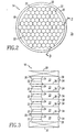
- the L-band sub-system 14 comprises a relatively large inflatable antenna assembly 18 which includes a torus support structure 20 (Figure 2) which is, for example, 50 meters in diameter and supports 91 contiguous reflector super elements 22.
- Figure 3 A cross-section of the antenna assembly 18 taken along the lines 3-3 of Figure 2 is shown in Figure 3.
- Each reflector cell 22 as shown in Figures 3 and 4A includes a mesh-type parabolic reflector 24 having a hexagonal outline or perimeter.
- the mesh reflector 24 is supported at its six corners by rigid post members 26 which when the antenna is deployed, stiffen the mesh reflector 24 as well back-up suspension cables 28 which form a web 30 and a set of drop lines 32 which act to pull the mesh-type reflector 24 into a parabolic shape.
- Each reflector super element 22 also includes a multi-element feed array 34 consisting of, for example, a cluster of thirty seven contiguous feed elements 36 as shown in Figure 5.
- the feed array 34 is suspended above the concave surface of the reflector 24 by means of a set of suspension cables 38 which extend between the rigid support posts 26 and the feed array 34.
- cable members 38 are also included along the edges of the mesh reflector 24 between the posts 26 so that the mesh does not stretch along the edges when the reflector surface is pulled down by the drop lines 32 and a suspension cable 28.
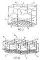
- Figure 4A discloses the mechanical details of a single reflector super element cell
- Figure 4B is illustrative of a group of seven contiguous reflector cells 22 1 , 22 2 , ... 22 7 .
- one support post 26 in many cases occurs at the intersection of three reflectors 24 of contiguous super element reflector cells such that, for example, at the intersection of three surfaces, a "Y" is formed.
- the rigid post elements 26 also act to maintain alignment of the various reflector cells 22.
- each feed array 34 includes thirty seven discrete feed elements 36 which are activated to transmit (Tx) and receive (Rx) power via a switch matrix 35 shown in Figure 6.
- the switch matrix 35 includes seven sets of switches 40 1 , 40 2 , ... 40 7 where the first six sets of switches 40 1 , ... 40 6 includes a set of five single-pole, double-throw switches, while the seventh set of switches 40 7 include seven single-pole, double-throw switches of which only six are used.
- each feed element is connected to a respective single-pole, double-throw switch.
- the seven sets of switches are connected to a 1:7 signal splitter 42, which is coupled to a circulator 44 which receives transmit signals from a power amplifier module 46 and feeds received signals to a low noise amplifier via a receiver protector device 50.
- the signal splitter 42 is operable to feed seven elements at a time in a pattern A, B, C, ... G shown in Figure 7 to form a cluster or group 37 of feed elements 36 at the position shown in Figure 5.
- This position comprises one of a plurality of positions on the face of the feed array 34, as shown, for example in Figures 8A, 8B and 8C.
- a group of seven feed elements are selected at the center of the array
- Figure 8B a group of seven elements are selected to the right of the array which corresponds to that shown in Figures 5 and 7
- the group shown in Figure 8C comprises a group of seven elements 36 located above and to the right of the array.
- a group 37 of feed elements 36 is not limited to a fixed number of elements, such as seven elements, but can be made to be variable with as many as, for example, twelve feed elements in a group, however, the design of Figure 6 would change.
- feed group selection includes selecting a specific feed group for a beam covered region wherein similar groups in each feed are selected, and wherein all of the super element individual reflectors produce a broad element pattern in the same direction.
- Time delay steering of the array factor results in providing fine steering control and is achieved by time delay units, not shown, which adjust the relative delay between super element reflector cells. Examples of array steering by reflector feed group selection and time delay steering the array factor is shown in Figures 9-12.
- FIGS 9A and 9B they are illustrative of the array steering mechanism where feed array 34 steers a super element beam generated by feed array 37 in Fig. 9A to O° with time delay units also steering the array factor to O°.
- the feed element of group 37 is centered in the feed element array 34.
- an antenna pattern as shown in Figure 9B results.
- reference numeral 52 depicts the super element beam pattern generated by the selected feed element group 37.
- the composite antenna pattern of the entire phased array antenna system as shown in Figures 2 and 3 a main lobe 54, and pairs of side lobes 55.
- Array factor steering is indicated by the position of a pair of grating lobes 56 on either side of the main lobe 54.
- Figures 10A and 10B are illustrative of the steering mechanism where group selection again steers the super element beam to 0° by centering the selected feed element in group 37 as shown in Figure 10A, but the array factor is now steered to 1.1° as shown in Figure 10B by the grating lobes 56.
- the main lobe 54 of the composite antenna pattern is also now at 1.1°.
- Figure 11A depicts feed group selection steering of the individual super element beam pattern of feed group 37 to 2.4°, but now the array factor is also steered to 2.4°, which is shown in Figure 11B and where an individual super element pattern 52 of feed group 37 and the main lobe 54 of the composite antenna pattern are both positioned at 2.4°.
- FIG. 12A shown thereat is a condition where group selection steers the respective super element beam pattern of feed group 39 (Fig. 12A) to 4.8°, while the array factor is steered to 6° as shown by the grating lobes 56 in Fig. 12B.
- the main lobe 54 of the composite antenna pattern is now also located at 6°.
- Figure 14C One possible variation of such an implementation shown in Figure 14A is shown in Figure 14C where six feed elements 36 are configured in a triangular group 62 as shown.
- Another method of reducing grating lobes 58 of the composite beam is to randomly select feed element groups about the optimum position as shown in Figures 15A, 15B and 15C where the configuration of the selected feed groups 37 a of feed array 34-1 is centered at 0°, while the feed groups 37 b and 37 c of feed arrays 34-1 and 34-2 as shown in Figures 15B and 15C are offset to the left and right relative to group 37 a .
- Such an arrangement would produce antenna patterns such as shown in Figure 15B, where the main lobe 54 of the composite pattern is located at 1.38° in elevation; however, the grating lobes 58 are significantly larger than those depicted in Figures 14B, being only 10dB down from the amplitude of the main lobe 54.
- Figures 16A-16D depict yet another method of mitigating the grating lobe problem. This involves gradual transitioning from one beam position to another. For example, as shown in Figure 16A, the feed element group 37 is centered, while in Figure 16B and 16C, an irregular pattern of feed elements depicts a transition to the final position as shown in Figure 16D. In each instance, the same number of feed elements are utilized.
- FIG. 17A, 17B and 17C Still another method of mitigating the grating lobe problem is shown in Figures 17A, 17B and 17C and comprises randomly positioning the feed arrays, for example, arrays 34-1, 34-2 and 34-3 about the focal point of the respective array which is shown located at the intersection of the X and Y axis.
- Figures 18A-18C and 19A-19D are illustrative of yet another method of mitigating the grating lobe problem, and involve adjusting the amplitude distribution of each element feed.
- the distributions are overlapped as required to precisely steer the feed array to the same position as the array factor.
- the drawback is that the feed array amplitudes are not uniform.
- Figures 18A and 18B depict two nominal distributions for beams at 0° and 2.4°. Overlapping distributions form a composite distribution as shown in Figure 18C which scans the element pattern horizontally exactly half way between beam positions. Thus for that position, there is no error between element pattern beam peak and array factor beam peak. Accordingly, grating lobes are reduced.
- translating the feed aperture forward of the focal plane 60 to a new location 62 provides a way to distribute the power more evenly across the feed array while precisely steering the element pattern to the same location as the array factor.
- the amplitude and phase of the feed array elements must be adjusted individually on transmit and receive.
- the precise feed point is determined analytically. An optimum feed is assumed to radiate from that point, and its radiation is projected to the feed plane. The distribution determined at the feed plane is then radiated from there. The benefit of this approach is to distribute the power among all the feed elements.
- the drawback is that the phase and amplitude must be controlled.
- the present invention permits the deployment of a Limited Field of View Antenna for Space Borne Applications by forming a plurality of reflector cells in a flexible reflective membrane using rigid support members that abut the flexible membrane at spaced locations and a mechanism, such as tension wires, that pulls the flexible membrane against the rigid support members to forms the reflector cells
Landscapes
- Physics & Mathematics (AREA)
- Electromagnetism (AREA)
- Engineering & Computer Science (AREA)
- Astronomy & Astrophysics (AREA)
- General Physics & Mathematics (AREA)
- Remote Sensing (AREA)
- Aviation & Aerospace Engineering (AREA)
- Aerials With Secondary Devices (AREA)
- Variable-Direction Aerials And Aerial Arrays (AREA)
- Details Of Aerials (AREA)
Abstract
Description
- This invention relates generally to antennas used for space applications and more particularly to a hybrid parabolic reflector phased array antenna which is stowed in a collapsed state for launch and thereafter deployed to form a relatively large reflector type antenna when in orbit.
- Extremely large scanning antennas for space applications and having limited scan requirements are well known. As the antenna is moved away from the earth, the scan angles are reduced, while the size of the antenna increases. The problem of deploying and steering very large antennas is formidable. Phased arrays generally have too many elements to be cost effective while reflector antennas have configuration problems in amount of blockage and performance degradation at the edges of scan.
- Currently, large scanning antennas use parabolic reflectors with clusters of elements at and near the focal point to scan the beam. In order to steer the antenna, a large group of elements are used to transmit and receive. On transmit, phase-only control is preferred, while on receive both phase and amplitude controls are used. Moreover, on transmit, amplitude is uniform while in receive it is normally tapered. In order to distribute the power among many elements to reduce the heat concentration, the feed array is typically displaced forward of the focal point; however, this increases the size of the feed rapidly, with commensurate increase in blockage loss.
- Apertures comprised of a plurality of reflector super elements, all having feed array generating respective antenna patterns, steer a composite beam pattern near the desired direction. In such apparatus, phase or time delay between elements is then used to fine steer the antenna. With large spacing between elements, however, grating lobes are formed, which is the classic problem of using a large element in a phased array. At beam positions between element pointing positions, there can be major grating lobes that sap the power from the main beam and that, in turn, raise serious clutter problems.
- The present invention is directed to a hybrid parabolic reflector phased array antenna system which is stowable in a rocket and is deployable in space. The antenna includes a large torus which acts as a support structure for a plurality of small reflector cells called super elements, each including its own reflector and an array of feed elements. The torus supports a stretched reflector mesh and matching back-up catanary wires that provide a mechanism for pulling the reflector surface of the cells down to an exact paraboloid. A set of rigid corner posts for stretching the mesh fabric for forming multiple reflectors is also provided. The torus is also used to support individual super element feed arrays for each reflector. The super elements incrementally scan the beam by group selection of feed elements in each feed array with time delay phase control being used to steer the array factor so as to achieve fine steering. Each of the super elements scans incrementally with a selected group of feed elements varying between seven and twelve, which are varied in position relative to the focal axis of the feed array. At intermediate positions, where grating lobes appear, the groups of feed elements are reduced in number and selected so as to steer precisely to this position, thus relieving the grating lobe problem. Other methods of mitigating the grating lobe problem include randomly selecting groups of elements about the optimum position, gradually shifting the selected group of elements from one position to another, randomly positioning the feed arrays about their respective focal points, and overlapping feed distributions to gradually shift the feed center and thus precisely adjusting the feed element pattern to agree with the array factor peak position.
- The present invention will become more fully understood from the detailed description provided hereinbelow and the accompanying drawings which are provided by way of illustration only, and thus are not limitative of the present invention, and wherein:
- Figure 1 is a perspective view generally illustrative of a space borne antenna system including an embodiment of the subject invention;
- Figure 2 is a front planar view of the L-band subsystem shown in Figure 1 which forms the subject invention;
- Figure 3 is illustrative of a cross-section of the antenna structure shown in Figure 2 taken along the lines 3-3 thereof;
- Figure 4A is a perspective view illustrative of the details of a single super element cell of the antenna structure shown in Figure 3;
- Figure 4 is a perspective view of seven contiguous super element cells for the antenna shown in Figures 2 and 3;
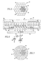
- Figure 5 is a front planar view of a multi-element feed array in accordance with the subject invention, with a group of seven feed elements being activated;
- Figure 6 is an electrical block diagram of control circuitry for selectively activating a selected group of feed elements shown in Figure 5;
- Figure 7 is a diagram illustrative of the physical arrangement of the feed elements which are activated in accordance with the control circuitry shown in Figure 6;
- Figures 8A, 8B and 8C are illustrative of the manner in which seven elements in a feed array can be selectively activated so as to move the group of activated elements over the face of the feed array;
- Figures 9A and 9B are illustrative of the array steering mechanism where feed group selection steers a super element beam at 0° with time delay units also steering the array factor to 0°;
- Figures 10A and 10B are illustrative of the array steering mechanism where feed group selection steers a super element beam to0° while time delay units steer the array factor to 1.1°.
- Figures 11A and 11B are illustrative of the array steering mechanism where feed group selection steers a super element beam to 2.4°;
- Figures 12A and 12B are illustrative of the array steering mechanism where feed group selection steers a super element beam to 4.8° while time delay units steer the array factor to 6°;
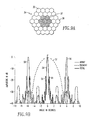
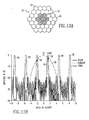
- Figures 13A and 13B are illustrative of an example of the grating lobe problem occurring when feed group selection steers a super element beam to 0° and time delay units steer the array factor in elevation to 1.386°;
- Figures 14A, 14B and 14C are illustrative of the method for reducing grating lobes by steering a feed group reduced in number to 1.386° in elevation where the array factor is scanned to 1.386° in elevation as shown in Figures 13B;
- Figures 15A-15D are illustrative of another method of reducing the grating lobe problem as shown in Figure 13B by randomly selecting feed groups;
- Figures 16A-16D are illustrative of still another method of mitigating the grating lobe problem and involves transitioning between beam positions; and
- Figures 17A-17C are illustrative of yet another method of mitigating the grating lobe problem and comprises random positioning of the feed arrays about respective focal axes.
- Figures 18A-18C are illustrative of still yet another method of mitigating the grating lobe problem which involves overlapping the amplitude distribution of feed elements to steer horizontally between nominal beam positions;
- Figures 19A-19D are illustrative of still yet another method of mitigating the grating lobe problem which involves overlapping the amplitude distribution of feed elements to steer vertically between nominal beam positions; and
- Figure 20 is a diagram illustrative of a method of distributing power more evenly across a feed array while steering the element pattern to the same location as the array factor.
- Referring now to the figures wherein like reference numerals refer to like parts throughout, Figure 1 depicts a space borne
antenna system 10 including anX-band sub-system 12 and an L-band sub-system 14. The present invention is directed to the L-band sub-system 14, the details of which are shown in Figures 2-4. The L-band sub-system 14 comprises a relatively largeinflatable antenna assembly 18 which includes a torus support structure 20 (Figure 2) which is, for example, 50 meters in diameter and supports 91 contiguous reflectorsuper elements 22. A cross-section of theantenna assembly 18 taken along the lines 3-3 of Figure 2 is shown in Figure 3. Eachreflector cell 22 as shown in Figures 3 and 4A includes a mesh-typeparabolic reflector 24 having a hexagonal outline or perimeter. Themesh reflector 24 is supported at its six corners byrigid post members 26 which when the antenna is deployed, stiffen themesh reflector 24 as well back-upsuspension cables 28 which form aweb 30 and a set ofdrop lines 32 which act to pull the mesh-type reflector 24 into a parabolic shape. - Each reflector
super element 22 also includes amulti-element feed array 34 consisting of, for example, a cluster of thirty sevencontiguous feed elements 36 as shown in Figure 5. Thefeed array 34, moreover, is suspended above the concave surface of thereflector 24 by means of a set ofsuspension cables 38 which extend between therigid support posts 26 and thefeed array 34. Although not immediately evident,cable members 38 are also included along the edges of themesh reflector 24 between theposts 26 so that the mesh does not stretch along the edges when the reflector surface is pulled down by thedrop lines 32 and asuspension cable 28. - While Figure 4A discloses the mechanical details of a single reflector
super element cell 22, Figure 4B is illustrative of a group of sevencontiguous reflector cells support post 26 in many cases occurs at the intersection of threereflectors 24 of contiguous super element reflector cells such that, for example, at the intersection of three surfaces, a "Y" is formed. Therigid post elements 26 also act to maintain alignment of thevarious reflector cells 22. - Referring now to Figures 5, 6 and 7, shown thereat are the details of the
feed array 34 for each reflectorsuper element 22. As noted above, eachfeed array 34 includes thirty sevendiscrete feed elements 36 which are activated to transmit (Tx) and receive (Rx) power via aswitch matrix 35 shown in Figure 6. Theswitch matrix 35 includes seven sets ofswitches switches 401, ... 406 includes a set of five single-pole, double-throw switches, while the seventh set ofswitches 407 include seven single-pole, double-throw switches of which only six are used. Thus, each feed element is connected to a respective single-pole, double-throw switch. The seven sets of switches are connected to a 1:7signal splitter 42, which is coupled to acirculator 44 which receives transmit signals from a power amplifier module 46 and feeds received signals to a low noise amplifier via areceiver protector device 50. - It can be seen with respect to Figure 7 that the
signal splitter 42 is operable to feed seven elements at a time in a pattern A, B, C, ... G shown in Figure 7 to form a cluster orgroup 37 offeed elements 36 at the position shown in Figure 5. This position comprises one of a plurality of positions on the face of thefeed array 34, as shown, for example in Figures 8A, 8B and 8C. As shown in Figure 8A, a group of seven feed elements are selected at the center of the array, whereas in Figure 8B, a group of seven elements are selected to the right of the array which corresponds to that shown in Figures 5 and 7, while the group shown in Figure 8C comprises a group of sevenelements 36 located above and to the right of the array. Agroup 37 offeed elements 36 is not limited to a fixed number of elements, such as seven elements, but can be made to be variable with as many as, for example, twelve feed elements in a group, however, the design of Figure 6 would change. - There are two mechanisms for steering the array. One comprises feed group selection. The other mechanism is time delay steering the array factor. Accordingly, where a plurality of super element reflector cells form a phased array antenna system such as shown in Figures 1-3, reflector feed group selection includes selecting a specific feed group for a beam covered region wherein similar groups in each feed are selected, and wherein all of the super element individual reflectors produce a broad element pattern in the same direction. Time delay steering of the array factor results in providing fine steering control and is achieved by time delay units, not shown, which adjust the relative delay between super element reflector cells. Examples of array steering by reflector feed group selection and time delay steering the array factor is shown in Figures 9-12.
- Referring now to Figures 9A and 9B they are illustrative of the array steering mechanism where
feed array 34 steers a super element beam generated byfeed array 37 in Fig. 9A to O° with time delay units also steering the array factor to O°. As shown in Figure 9A, the feed element ofgroup 37 is centered in thefeed element array 34. With no array factor steering being applied, an antenna pattern as shown in Figure 9B results. In Figure 9B,reference numeral 52 depicts the super element beam pattern generated by the selectedfeed element group 37. The composite antenna pattern of the entire phased array antenna system as shown in Figures 2 and 3 amain lobe 54, and pairs ofside lobes 55. Array factor steering is indicated by the position of a pair of gratinglobes 56 on either side of themain lobe 54. - Figures 10A and 10B are illustrative of the steering mechanism where group selection again steers the super element beam to 0° by centering the selected feed element in
group 37 as shown in Figure 10A, but the array factor is now steered to 1.1° as shown in Figure 10B by thegrating lobes 56. Themain lobe 54 of the composite antenna pattern is also now at 1.1°. - Next, considering Figures 11A and 11B, Figure 11A depicts feed group selection steering of the individual super element beam pattern of
feed group 37 to 2.4°, but now the array factor is also steered to 2.4°, which is shown in Figure 11B and where an individualsuper element pattern 52 offeed group 37 and themain lobe 54 of the composite antenna pattern are both positioned at 2.4°. - Referring now to Figures 12A and 12B, shown thereat is a condition where group selection steers the respective super element beam pattern of feed group 39 (Fig. 12A) to 4.8°, while the array factor is steered to 6° as shown by the
grating lobes 56 in Fig. 12B. Themain lobe 54 of the composite antenna pattern is now also located at 6°. - It should be noted, however, that there exists some scan positions where a grating lobe problem arises particularly as it pertains to the composite pattern. For example, as shown in Figures 13A and 13B where feed element group selection (Fig. 13A) steers the super element beam to 0°, but the array factor is steered in elevation to 1.386°. As shown in Figure 13B, it can be seen that while the
main lobe 54 of the composite pattern is located at 1.386°, agrating lobe 58 of the composite pattern which is significant in amplitude (down 5dB) relative to themain lobe 54 is generated. - This undesirable condition can be overcome by in accordance with this invention selecting a reduced
feed element group 60, as shown in Figure 14A, which consists in a group of only threefeed elements 36 and aiming the beam generated by the feed element group 60 (Fig. 14A) at the 1.386° position in elevation. It can be seen in Fig. 14B that the undesirable gratinglobe 58 of the composite beam pattern is reduced by almost 20dB in amplitude relative to themain lobe 54 of the composite beam pattern. - One possible variation of such an implementation shown in Figure 14A is shown in Figure 14C where six
feed elements 36 are configured in atriangular group 62 as shown. - Another method of reducing
grating lobes 58 of the composite beam is to randomly select feed element groups about the optimum position as shown in Figures 15A, 15B and 15C where the configuration of the selectedfeed groups 37a of feed array 34-1 is centered at 0°, while thefeed groups group 37a. Such an arrangement would produce antenna patterns such as shown in Figure 15B, where themain lobe 54 of the composite pattern is located at 1.38° in elevation; however, thegrating lobes 58 are significantly larger than those depicted in Figures 14B, being only 10dB down from the amplitude of themain lobe 54. - Figures 16A-16D depict yet another method of mitigating the grating lobe problem. This involves gradual transitioning from one beam position to another. For example, as shown in Figure 16A, the
feed element group 37 is centered, while in Figure 16B and 16C, an irregular pattern of feed elements depicts a transition to the final position as shown in Figure 16D. In each instance, the same number of feed elements are utilized. - Still another method of mitigating the grating lobe problem is shown in Figures 17A, 17B and 17C and comprises randomly positioning the feed arrays, for example, arrays 34-1, 34-2 and 34-3 about the focal point of the respective array which is shown located at the intersection of the X and Y axis.
- Figures 18A-18C and 19A-19D are illustrative of yet another method of mitigating the grating lobe problem, and involve adjusting the amplitude distribution of each element feed. The distributions are overlapped as required to precisely steer the feed array to the same position as the array factor. The drawback is that the feed array amplitudes are not uniform.
- Figures 18A and 18B, for example, depict two nominal distributions for beams at 0° and 2.4°. Overlapping distributions form a composite distribution as shown in Figure 18C which scans the element pattern horizontally exactly half way between beam positions. Thus for that position, there is no error between element pattern beam peak and array factor beam peak. Accordingly, grating lobes are reduced.
- With respect to Figures 19A, 19B, and 19C, shown thereat are three nominal distributions for beams at θ=0°, ϕ=30° and θ=2.4°, and ϕ=30° and θ=2.4°. Overlapping distributions form a composite distribution as shown in Figure 19D to vertically steer the element pattern exactly to the intersection between positions. Thus for that position, there is no error between element pattern beam peak and array factor beam peak, and thus grating lobes are reduced.
- Referring now to Figure 20, translating the feed aperture forward of the
focal plane 60 to anew location 62 provides a way to distribute the power more evenly across the feed array while precisely steering the element pattern to the same location as the array factor. In this configuration, the amplitude and phase of the feed array elements must be adjusted individually on transmit and receive. In Figure 20, the precise feed point is determined analytically. An optimum feed is assumed to radiate from that point, and its radiation is projected to the feed plane. The distribution determined at the feed plane is then radiated from there. The benefit of this approach is to distribute the power among all the feed elements. The drawback is that the phase and amplitude must be controlled. - From the above, it will be appreciated that the present invention permits the deployment of a Limited Field of View Antenna for Space Borne Applications by forming a plurality of reflector cells in a flexible reflective membrane using rigid support members that abut the flexible membrane at spaced locations and a mechanism, such as tension wires, that pulls the flexible membrane against the rigid support members to forms the reflector cells
- Having thus shown and described what is at present considered to be the preferred embodiments of the invention, it should be noted that the same has been made by way of illustration and not limitation. Accordingly, all modifications, alterations and changes coming within the spirit and scope of the invention as set forth in the appended claims are herein meant to be included.
Claims (25)
- A hybrid parabolic reflector phased array antenna, adapted for deployment in space, comprising:a reflector support structure;a plurality of parabolic reflector cells mounted side by side in an open interior portion of the support structure;each reflector cell including an RF signal reflector and an array of the RF signal feed elements;each reflector having a flexible reflecting surface and a plurality of elongated edges defining a geometric shape, and including respective corner portions at the intersection of pairs of edges;respective rigid support members located at the corner portions of the reflector for stiffening the reflector and the elongated edges, and also for providing a support for the array of feed elements;a set of flexible support members extending between the rigid support members of each reflector cell and the respective array of feed elements for positioning the array above the RF signal reflector, anda mechanism located beneath each of the RF signal reflector for pulling the flexible reflecting surface down to a substantially parabolic shape.
- An antenna structure according to claim 1 wherein the reflector support structure comprises a toroidal support structure.
- An antenna structure according to claim 1 wherein said plurality of parabolic reflector cells are comprised of super element reflector cells arranged in a planar array.
- An antenna according to claim 1, and additionally including a support member located at the edges of the reflecting surface to prevent stretching of the reflector along the edges.
- An antenna according to claim 1 wherein said rigid support members comprise a plurality of elongated posts.
- An antenna according to claim 1 wherein said set of flexible support members comprises wire support members.
- An antenna according to claim 1 wherein said mechanism for pulling the reflecting surface down comprises a backup structure including a set of wires and tension cables.
- An antenna according to claim 1 wherein said flexible reflecting surface comprises a reflector mesh.
- An antenna according to claim 1 wherein said array of feed elements comprises a planar array of feed elements.
- An antenna according to claim 9 wherein said array of feed elements in each reflector cell is selectively activated in groups of feed elements and wherein said groups are varied in position relative to a focal point of the array to steer a transmitted and/or received beam generated by one or more of the reflector cells.
- An antenna according to claim 10 wherein the array is also steered by steering of the array factor.
- An antenna according to claim 10 wherein the array is steered to a position where an undesired grating lobe appears for relieving a grating lobe problem.
- An antenna according to claim 12 wherein the number of feed elements in at least one of the group is also reduced for relieving the gating lobe problem.
- An antenna according to claim 10 wherein said groups of feed elements are randomly selected so as to be positioned about a predetermined position of the planar array of feed elements for relieving a grating lobe problem.
- An antenna according to claim 10 wherein said groups of feed elements are gradually shifted from one position to another for relieving a gating lobe position.
- An antenna according to claim 10 wherein said groups of feed elements are randomly positioned about respective focal points of the planar arrays for relieving a grating lobe problem.
- A method of steering a transmitted and/or received beam of a phased array antenna system including a plurality of super element reflector cells each including a parabolic reflector element and a plurality of feed elements arranged in a planar array and being mounted on a support structure, comprising the steps of:activating the feed elements of each feed array in selected groups of feed elements at predetermined locations relative to the focal point of the respective array to achieve a course scan of the beam; andsteering the array factor of the beam to achieve a fine scan of the beam.
- A method according to claim 17 and additionally including the step of overlapping feed distributions of said feed array to gradually shift the feed center of the array to steer the beam between nominal beam positions.
- A method according to claim 17 and additionally including the step of steering the beam via group selection to substantially the exact location of a grating lobe for relieving an undesirable grating lobe problem.
- A method according to claim 19 and additionally including the step of reducing the number of feed elements selected in a group for relieving an undesirable grating lobe problem.
- A method according to claim 17 and additionally including the step of randomly selecting groups of feed elements for positioning said groups about a predetermined position on the feed array for relieving an undesirable grating lobe problem.
- A method according to claim 17 and additionally including the step of gradually shifting certain groups of feed elements from one position to another for relieving a grating lobe problem.
- A method according to claim 17 and additionally including the step of selecting groups of feed elements so as to be randomly positioned about respective focal points of the planar arrays for relieving a grating lobe problem.
- A method according to claim 17 and additionally including the step of overlapping feed distributions of said feed array to steer the feed array to the same position as the array factor peak position for relieving an undesirable grating lobe problem.
- A method according to claim 17 and additionally including the step of stowing the antenna system in a collapsed state for launch and thereafter deploying the antenna for operation in space.
Applications Claiming Priority (4)
| Application Number | Priority Date | Filing Date | Title |
|---|---|---|---|
| US17728200P | 2000-01-21 | 2000-01-21 | |
| US177282P | 2000-01-21 | ||
| US596492 | 2000-06-19 | ||
| US09/596,492 US6836255B1 (en) | 2000-01-21 | 2000-06-19 | Limited field of view antenna for space borne applications |
Publications (3)
| Publication Number | Publication Date |
|---|---|
| EP1168497A2 true EP1168497A2 (en) | 2002-01-02 |
| EP1168497A3 EP1168497A3 (en) | 2003-12-10 |
| EP1168497B1 EP1168497B1 (en) | 2004-09-15 |
Family
ID=26873117
Family Applications (1)
| Application Number | Title | Priority Date | Filing Date |
|---|---|---|---|
| EP00128643A Expired - Lifetime EP1168497B1 (en) | 2000-01-21 | 2000-12-28 | Limited field of view antenna for space borne applications |
Country Status (4)
| Country | Link |
|---|---|
| US (1) | US6836255B1 (en) |
| EP (1) | EP1168497B1 (en) |
| AT (1) | ATE276592T1 (en) |
| DE (1) | DE60013792T2 (en) |
Cited By (3)
| Publication number | Priority date | Publication date | Assignee | Title |
|---|---|---|---|---|
| WO2009048678A3 (en) * | 2007-08-28 | 2009-05-28 | Raytheon Co | A space vehicle having a payload-centric configuration |
| CN107153729A (en) * | 2017-04-27 | 2017-09-12 | 西安电子科技大学 | A kind of form Design method of cable net structure before deployable parabola antenna |
| CN111555011A (en) * | 2018-12-29 | 2020-08-18 | 长沙天仪空间科技研究院有限公司 | A Deployable Inflatable Antenna for Satellites |
Families Citing this family (7)
| Publication number | Priority date | Publication date | Assignee | Title |
|---|---|---|---|---|
| JP2004266333A (en) * | 2003-01-30 | 2004-09-24 | Matsushita Electric Ind Co Ltd | Antenna device |
| US20070200763A1 (en) * | 2006-02-28 | 2007-08-30 | Harris Corporation | Phased array antenna including flexible layers and associated methods |
| EP2643882B1 (en) | 2010-12-15 | 2014-04-16 | Skybox Imaging, Inc. | Integrated antenna system for imaging microsatellites |
| US9755318B2 (en) * | 2014-01-09 | 2017-09-05 | Northrop Grumman Systems Corporation | Mesh reflector with truss structure |
| EP3109939B1 (en) * | 2015-06-26 | 2024-01-03 | HENSOLDT Sensors GmbH | Dual-band phased array antenna with built-in grating lobe mitigation |
| EP3361572B1 (en) | 2015-10-26 | 2020-12-02 | Huawei Technologies Co., Ltd. | Reflector antenna and antenna alignment method |
| WO2024108127A1 (en) * | 2022-11-17 | 2024-05-23 | Commscope Technologies Llc | Radio frequency feed networks having selective capacitive coupling, and related methods of operating a base station antenna |
Family Cites Families (3)
| Publication number | Priority date | Publication date | Assignee | Title |
|---|---|---|---|---|
| US4259674A (en) | 1979-10-24 | 1981-03-31 | Bell Laboratories | Phased array antenna arrangement with filtering to reduce grating lobes |
| JPS6483741A (en) | 1987-09-24 | 1989-03-29 | Mitsubishi Electric Corp | Expansion structure |
| US6268835B1 (en) * | 2000-01-07 | 2001-07-31 | Trw Inc. | Deployable phased array of reflectors and method of operation |
-
2000
- 2000-06-19 US US09/596,492 patent/US6836255B1/en not_active Expired - Fee Related
- 2000-12-28 DE DE60013792T patent/DE60013792T2/en not_active Expired - Fee Related
- 2000-12-28 EP EP00128643A patent/EP1168497B1/en not_active Expired - Lifetime
- 2000-12-28 AT AT00128643T patent/ATE276592T1/en not_active IP Right Cessation
Cited By (6)
| Publication number | Priority date | Publication date | Assignee | Title |
|---|---|---|---|---|
| WO2009048678A3 (en) * | 2007-08-28 | 2009-05-28 | Raytheon Co | A space vehicle having a payload-centric configuration |
| US7686255B2 (en) | 2007-08-28 | 2010-03-30 | Raytheon Company | Space vehicle having a payload-centric configuration |
| CN107153729A (en) * | 2017-04-27 | 2017-09-12 | 西安电子科技大学 | A kind of form Design method of cable net structure before deployable parabola antenna |
| CN107153729B (en) * | 2017-04-27 | 2019-08-09 | 西安电子科技大学 | A Form Design Method for Front Cable Net Structure of Deployable Parabolic Antenna |
| CN111555011A (en) * | 2018-12-29 | 2020-08-18 | 长沙天仪空间科技研究院有限公司 | A Deployable Inflatable Antenna for Satellites |
| CN111555011B (en) * | 2018-12-29 | 2023-01-24 | 长沙天仪空间科技研究院有限公司 | Deployable inflatable antenna suitable for satellite |
Also Published As
| Publication number | Publication date |
|---|---|
| ATE276592T1 (en) | 2004-10-15 |
| DE60013792T2 (en) | 2005-09-29 |
| US6836255B1 (en) | 2004-12-28 |
| EP1168497B1 (en) | 2004-09-15 |
| EP1168497A3 (en) | 2003-12-10 |
| DE60013792D1 (en) | 2004-10-21 |
Similar Documents
| Publication | Publication Date | Title |
|---|---|---|
| US6268835B1 (en) | Deployable phased array of reflectors and method of operation | |
| US11056773B2 (en) | Twin-beam base station antennas having thinned arrays with triangular sub-arrays | |
| US5276452A (en) | Scan compensation for array antenna on a curved surface | |
| KR101780842B1 (en) | Reflector array antenna with crossed polarization compensation and method for producing such an antenna | |
| US3835469A (en) | Optical limited scan antenna system | |
| US8237619B2 (en) | Dual beam sector antenna array with low loss beam forming network | |
| US6456252B1 (en) | Phase-only reconfigurable multi-feed reflector antenna for shaped beams | |
| EP0963006B1 (en) | Reconfigurable multiple beam satellite phased array antenna | |
| EP2485328B1 (en) | Antenna system for low-earth-orbit satellites | |
| US5589843A (en) | Antenna system with tapered aperture antenna and microstrip phase shifting feed network | |
| US5079557A (en) | Phased array antenna architecture and related method | |
| EP1168497B1 (en) | Limited field of view antenna for space borne applications | |
| WO2000036705A1 (en) | Dual mode switched beam antenna | |
| US6690333B2 (en) | Cylindrical ray imaging steered beam array (CRISBA) antenna | |
| US5929823A (en) | Multiple beam planar array with parasitic elements | |
| US6388637B1 (en) | Wide band, wide scan antenna for space borne applications | |
| US6384782B2 (en) | Antenna arrangement and method for side-lobe suppression | |
| US6323815B1 (en) | Antenna configuration for low and medium earth orbit satellites | |
| JP3061504B2 (en) | Array antenna | |
| JPH01503429A (en) | Microwave lens and array antenna | |
| WO2019075236A2 (en) | User insensitive steerable antenna array devices, systems, and methods | |
| CN107546478A (en) | Using the large-angle scanning phased array antenna and design method of particular orientation figure array element | |
| US12132255B2 (en) | Multibeam antenna | |
| US6441785B1 (en) | Low sidelobe antenna with beams steerable in one direction | |
| USRE28217E (en) | Antenna with electrically variable reflector |
Legal Events
| Date | Code | Title | Description |
|---|---|---|---|
| PUAI | Public reference made under article 153(3) epc to a published international application that has entered the european phase |
Free format text: ORIGINAL CODE: 0009012 |
|
| AK | Designated contracting states |
Kind code of ref document: A2 Designated state(s): AT BE CH CY DE DK ES FI FR GB GR IE IT LI LU MC NL PT SE TR |
|
| AX | Request for extension of the european patent |
Free format text: AL;LT;LV;MK;RO;SI |
|
| PUAL | Search report despatched |
Free format text: ORIGINAL CODE: 0009013 |
|
| AK | Designated contracting states |
Kind code of ref document: A3 Designated state(s): AT BE CH CY DE DK ES FI FR GB GR IE IT LI LU MC NL PT SE TR |
|
| AX | Request for extension of the european patent |
Extension state: AL LT LV MK RO SI |
|
| 17P | Request for examination filed |
Effective date: 20031230 |
|
| GRAP | Despatch of communication of intention to grant a patent |
Free format text: ORIGINAL CODE: EPIDOSNIGR1 |
|
| GRAS | Grant fee paid |
Free format text: ORIGINAL CODE: EPIDOSNIGR3 |
|
| GRAA | (expected) grant |
Free format text: ORIGINAL CODE: 0009210 |
|
| AKX | Designation fees paid |
Designated state(s): AT BE CH CY DE DK ES FI FR GB GR IE IT LI LU MC NL PT SE TR |
|
| AK | Designated contracting states |
Kind code of ref document: B1 Designated state(s): AT BE CH CY DE DK ES FI FR GB GR IE IT LI LU MC NL PT SE TR |
|
| PG25 | Lapsed in a contracting state [announced via postgrant information from national office to epo] |
Ref country code: IT Free format text: LAPSE BECAUSE OF FAILURE TO SUBMIT A TRANSLATION OF THE DESCRIPTION OR TO PAY THE FEE WITHIN THE PRESCRIBED TIME-LIMIT;WARNING: LAPSES OF ITALIAN PATENTS WITH EFFECTIVE DATE BEFORE 2007 MAY HAVE OCCURRED AT ANY TIME BEFORE 2007. THE CORRECT EFFECTIVE DATE MAY BE DIFFERENT FROM THE ONE RECORDED. Effective date: 20040915 Ref country code: BE Free format text: LAPSE BECAUSE OF FAILURE TO SUBMIT A TRANSLATION OF THE DESCRIPTION OR TO PAY THE FEE WITHIN THE PRESCRIBED TIME-LIMIT Effective date: 20040915 Ref country code: LI Free format text: LAPSE BECAUSE OF FAILURE TO SUBMIT A TRANSLATION OF THE DESCRIPTION OR TO PAY THE FEE WITHIN THE PRESCRIBED TIME-LIMIT Effective date: 20040915 Ref country code: CH Free format text: LAPSE BECAUSE OF FAILURE TO SUBMIT A TRANSLATION OF THE DESCRIPTION OR TO PAY THE FEE WITHIN THE PRESCRIBED TIME-LIMIT Effective date: 20040915 Ref country code: CY Free format text: LAPSE BECAUSE OF FAILURE TO SUBMIT A TRANSLATION OF THE DESCRIPTION OR TO PAY THE FEE WITHIN THE PRESCRIBED TIME-LIMIT Effective date: 20040915 Ref country code: TR Free format text: LAPSE BECAUSE OF FAILURE TO SUBMIT A TRANSLATION OF THE DESCRIPTION OR TO PAY THE FEE WITHIN THE PRESCRIBED TIME-LIMIT Effective date: 20040915 Ref country code: FI Free format text: LAPSE BECAUSE OF FAILURE TO SUBMIT A TRANSLATION OF THE DESCRIPTION OR TO PAY THE FEE WITHIN THE PRESCRIBED TIME-LIMIT Effective date: 20040915 Ref country code: NL Free format text: LAPSE BECAUSE OF FAILURE TO SUBMIT A TRANSLATION OF THE DESCRIPTION OR TO PAY THE FEE WITHIN THE PRESCRIBED TIME-LIMIT Effective date: 20040915 Ref country code: AT Free format text: LAPSE BECAUSE OF FAILURE TO SUBMIT A TRANSLATION OF THE DESCRIPTION OR TO PAY THE FEE WITHIN THE PRESCRIBED TIME-LIMIT Effective date: 20040915 |
|
| REG | Reference to a national code |
Ref country code: GB Ref legal event code: FG4D Ref country code: CH Ref legal event code: EP |
|
| REG | Reference to a national code |
Ref country code: IE Ref legal event code: FG4D |
|
| REF | Corresponds to: |
Ref document number: 60013792 Country of ref document: DE Date of ref document: 20041021 Kind code of ref document: P |
|
| PGFP | Annual fee paid to national office [announced via postgrant information from national office to epo] |
Ref country code: NL Payment date: 20041129 Year of fee payment: 5 |
|
| REG | Reference to a national code |
Ref country code: SE Ref legal event code: TRGR |
|
| PG25 | Lapsed in a contracting state [announced via postgrant information from national office to epo] |
Ref country code: GR Free format text: LAPSE BECAUSE OF FAILURE TO SUBMIT A TRANSLATION OF THE DESCRIPTION OR TO PAY THE FEE WITHIN THE PRESCRIBED TIME-LIMIT Effective date: 20041215 Ref country code: DK Free format text: LAPSE BECAUSE OF FAILURE TO SUBMIT A TRANSLATION OF THE DESCRIPTION OR TO PAY THE FEE WITHIN THE PRESCRIBED TIME-LIMIT Effective date: 20041215 |
|
| PG25 | Lapsed in a contracting state [announced via postgrant information from national office to epo] |
Ref country code: ES Free format text: LAPSE BECAUSE OF FAILURE TO SUBMIT A TRANSLATION OF THE DESCRIPTION OR TO PAY THE FEE WITHIN THE PRESCRIBED TIME-LIMIT Effective date: 20041226 |
|
| PGFP | Annual fee paid to national office [announced via postgrant information from national office to epo] |
Ref country code: BE Payment date: 20050119 Year of fee payment: 5 |
|
| REG | Reference to a national code |
Ref country code: CH Ref legal event code: PL |
|
| NLV1 | Nl: lapsed or annulled due to failure to fulfill the requirements of art. 29p and 29m of the patents act | ||
| ET | Fr: translation filed | ||
| PLBE | No opposition filed within time limit |
Free format text: ORIGINAL CODE: 0009261 |
|
| STAA | Information on the status of an ep patent application or granted ep patent |
Free format text: STATUS: NO OPPOSITION FILED WITHIN TIME LIMIT |
|
| 26N | No opposition filed |
Effective date: 20050616 |
|
| PGFP | Annual fee paid to national office [announced via postgrant information from national office to epo] |
Ref country code: FR Payment date: 20061220 Year of fee payment: 7 |
|
| PGFP | Annual fee paid to national office [announced via postgrant information from national office to epo] |
Ref country code: GB Payment date: 20061222 Year of fee payment: 7 |
|
| PGFP | Annual fee paid to national office [announced via postgrant information from national office to epo] |
Ref country code: SE Payment date: 20061227 Year of fee payment: 7 |
|
| PGFP | Annual fee paid to national office [announced via postgrant information from national office to epo] |
Ref country code: DE Payment date: 20070131 Year of fee payment: 7 |
|
| PG25 | Lapsed in a contracting state [announced via postgrant information from national office to epo] |
Ref country code: PT Free format text: LAPSE BECAUSE OF NON-PAYMENT OF DUE FEES Effective date: 20050215 |
|
| PGFP | Annual fee paid to national office [announced via postgrant information from national office to epo] |
Ref country code: MC Payment date: 20071204 Year of fee payment: 8 |
|
| PGFP | Annual fee paid to national office [announced via postgrant information from national office to epo] |
Ref country code: LU Payment date: 20080107 Year of fee payment: 8 |
|
| EUG | Se: european patent has lapsed | ||
| GBPC | Gb: european patent ceased through non-payment of renewal fee |
Effective date: 20071228 |
|
| PG25 | Lapsed in a contracting state [announced via postgrant information from national office to epo] |
Ref country code: DE Free format text: LAPSE BECAUSE OF NON-PAYMENT OF DUE FEES Effective date: 20080701 Ref country code: SE Free format text: LAPSE BECAUSE OF NON-PAYMENT OF DUE FEES Effective date: 20071229 |
|
| REG | Reference to a national code |
Ref country code: FR Ref legal event code: ST Effective date: 20081020 |
|
| PG25 | Lapsed in a contracting state [announced via postgrant information from national office to epo] |
Ref country code: GB Free format text: LAPSE BECAUSE OF NON-PAYMENT OF DUE FEES Effective date: 20071228 |
|
| PG25 | Lapsed in a contracting state [announced via postgrant information from national office to epo] |
Ref country code: FR Free format text: LAPSE BECAUSE OF NON-PAYMENT OF DUE FEES Effective date: 20071231 |
|
| PG25 | Lapsed in a contracting state [announced via postgrant information from national office to epo] |
Ref country code: MC Free format text: LAPSE BECAUSE OF NON-PAYMENT OF DUE FEES Effective date: 20081231 |
|
| PGFP | Annual fee paid to national office [announced via postgrant information from national office to epo] |
Ref country code: IE Payment date: 20071224 Year of fee payment: 8 |
|
| REG | Reference to a national code |
Ref country code: IE Ref legal event code: MM4A |
|
| PG25 | Lapsed in a contracting state [announced via postgrant information from national office to epo] |
Ref country code: IE Free format text: LAPSE BECAUSE OF NON-PAYMENT OF DUE FEES Effective date: 20081229 |
|
| PG25 | Lapsed in a contracting state [announced via postgrant information from national office to epo] |
Ref country code: LU Free format text: LAPSE BECAUSE OF NON-PAYMENT OF DUE FEES Effective date: 20081228 |