EP1168056A2 - Apparatus and method of loading a film in a reusable camera wherein culling of defective cameras is delayed - Google Patents

Apparatus and method of loading a film in a reusable camera wherein culling of defective cameras is delayed Download PDF

Info

Publication number
EP1168056A2
EP1168056A2 EP01202123A EP01202123A EP1168056A2 EP 1168056 A2 EP1168056 A2 EP 1168056A2 EP 01202123 A EP01202123 A EP 01202123A EP 01202123 A EP01202123 A EP 01202123A EP 1168056 A2 EP1168056 A2 EP 1168056A2
Authority
EP
European Patent Office
Prior art keywords
camera frame
frame assemblies
film
defects
pallets
Prior art date
Legal status (The legal status is an assumption and is not a legal conclusion. Google has not performed a legal analysis and makes no representation as to the accuracy of the status listed.)
Withdrawn
Application number
EP01202123A
Other languages
German (de)
French (fr)
Other versions
EP1168056A3 (en
Inventor
Michael L. c/o Eastman Kodak Company DeCecca
Joseph A. c/o Eastman Kodak Company Watkins
Jacob M. c/o Eastman Kodak Company Shmois
Robert J. c/o Eastman Kodak Company Blank
James Joseph Jr. Eastman Kodak Company Parker
Current Assignee (The listed assignees may be inaccurate. Google has not performed a legal analysis and makes no representation or warranty as to the accuracy of the list.)
Eastman Kodak Co
Original Assignee
Eastman Kodak Co
Priority date (The priority date is an assumption and is not a legal conclusion. Google has not performed a legal analysis and makes no representation as to the accuracy of the date listed.)
Filing date
Publication date
Application filed by Eastman Kodak Co filed Critical Eastman Kodak Co
Publication of EP1168056A2 publication Critical patent/EP1168056A2/en
Publication of EP1168056A3 publication Critical patent/EP1168056A3/en
Withdrawn legal-status Critical Current

Links

Images

Classifications

    • GPHYSICS
    • G03PHOTOGRAPHY; CINEMATOGRAPHY; ANALOGOUS TECHNIQUES USING WAVES OTHER THAN OPTICAL WAVES; ELECTROGRAPHY; HOLOGRAPHY
    • G03BAPPARATUS OR ARRANGEMENTS FOR TAKING PHOTOGRAPHS OR FOR PROJECTING OR VIEWING THEM; APPARATUS OR ARRANGEMENTS EMPLOYING ANALOGOUS TECHNIQUES USING WAVES OTHER THAN OPTICAL WAVES; ACCESSORIES THEREFOR
    • G03B17/00Details of cameras or camera bodies; Accessories therefor
    • G03B17/26Holders for containing light sensitive material and adapted to be inserted within the camera
    • YGENERAL TAGGING OF NEW TECHNOLOGICAL DEVELOPMENTS; GENERAL TAGGING OF CROSS-SECTIONAL TECHNOLOGIES SPANNING OVER SEVERAL SECTIONS OF THE IPC; TECHNICAL SUBJECTS COVERED BY FORMER USPC CROSS-REFERENCE ART COLLECTIONS [XRACs] AND DIGESTS
    • Y10TECHNICAL SUBJECTS COVERED BY FORMER USPC
    • Y10TTECHNICAL SUBJECTS COVERED BY FORMER US CLASSIFICATION
    • Y10T29/00Metal working
    • Y10T29/53Means to assemble or disassemble
    • Y10T29/53022Means to assemble or disassemble with means to test work or product
    • YGENERAL TAGGING OF NEW TECHNOLOGICAL DEVELOPMENTS; GENERAL TAGGING OF CROSS-SECTIONAL TECHNOLOGIES SPANNING OVER SEVERAL SECTIONS OF THE IPC; TECHNICAL SUBJECTS COVERED BY FORMER USPC CROSS-REFERENCE ART COLLECTIONS [XRACs] AND DIGESTS
    • Y10TECHNICAL SUBJECTS COVERED BY FORMER USPC
    • Y10TTECHNICAL SUBJECTS COVERED BY FORMER US CLASSIFICATION
    • Y10T29/00Metal working
    • Y10T29/53Means to assemble or disassemble
    • Y10T29/53313Means to interrelatedly feed plural work parts from plural sources without manual intervention
    • Y10T29/5337Means to interrelatedly feed plural work parts from plural sources without manual intervention including assembly pallet

Definitions

  • FIG. 1 illustrates one embodiment of a one-time-use camera 38.
  • the camera 38 has a front cover 40, a back or back cover 42, and a frame unit 44 located between covers 40,42.
  • a first film chamber 46 can contain a coreless film roll 34 or can have a film roll 34 held by a spool (not illustrated).
  • a second film chamber 48 holds the film cartridge 22.
  • the end of the filmstrip 32 is attached to a cartridge spool 50 within the canister 36.
  • a thumbwheel 51 is joined to the cartridge spool 50.
  • the frame unit 44 defines a film path (indicated by arrow 52 in Figure 2) along which the photographic filmstrip 32 travels as the filmstrip is advanced during use.
  • the film path extends from the first film chamber 46, across an intermediate section 54 to the second film chamber 48.
  • the intermediate section 54 includes an exposure area to which light is directed by an exposure unit 56.
  • the exposure unit 56 includes sub-components such as a baffle, a lens system, a shutter, and a shutter release (not separately illustrated).
  • the camera 38 can include a variety of other well-known camera features.
  • the intermediate section 54 can include frame rails for supporting the film during camera use. Discrete camera constituents, such as, a flash system 47, a viewfinder, and a battery (not separately illustrated); can also be installed in the camera during assembly.
  • pallets 16 are placed on the transporter 14, as indicated by arrows 109.
  • Camera frame assemblies 18, that is, incomplete camera bodies, are then placed on respective pallets 16.
  • Film cartridges 22 are placed on the pallets 16 with the camera frame assemblies 18.
  • the two streams of pallets 16 are then brought together at the intersection 60.
  • the order of the pallets 16 leaving the intersection 60 can be indeterminate. In other words, pallets 16 need not be provided by the two branches 58 at the same rate and the rate for each branch 58 can vary with time. This is likely, for example, if the steps of the first portion 20 of the system 10 are done manually.
  • the film cartridge 22 is placed in the camera frame assembly 18 and the film is prewound out of the cartridge 22.
  • a back 42 is then placed over the camera frame assembly 18 light tightly closing the camera frame assembly 18. The pallets 16 then leave the dark enclosure 28.
  • the camera frame assemblies 18 are illustrated as bearing identifiers 110, in the form of bar-codes, at an early stage of the assembly process. Because the pallet bar-codes 108 are used to register information in the table, the camera identifiers 110 can be added whenever convenient. Defective cameras can be unnumbered, allowing continuous numbering of identifiers 110 of cameras packaged together for distribution. Monitoring is easier, since camera identifiers 110 can be provided in continuous blocks of numbers. The use of pallet bar-codes 108 also avoids any problems that could result from using film cartridge identifiers 112 to also identify cameras, such as possible confusion during reuse of film cartridges from defective cameras.
  • the tabulated information about each pallet 16 is used in culling defective camera frame assemblies 18 at the completion of the process.
  • This is a particularly advantageous approach, in that testing can be provided in the dark enclosure 28, without requiring access for culling of defective camera frame assemblies 18 at that time.
  • Defective camera frame assemblies 18 can instead be tested for defects within the dark enclosure 28 and then be culled later after completing the assembly process.
  • camera frame assemblies 18 can be tested and defective camera frame assemblies 18 can be easily removed, since it is easy to do so within the daylight environment.
  • the first portion 20 of the system 10 can be simplified by eliminating the removal of defective camera frame assemblies 18.
  • the camera frame assemblies 18 are tested, defects are recorded, and defective camera frame assemblies 18 are then allowed to continue through the assembly process for culling at the end.
  • This approach also helps ensure the integrity of information in the controller. All pallets 16 enter and leave the system 10 only at the beginning and end, and all pallets 16 within the system 10 are continuously tracked in the table.
  • the printer 116 prints defect indicators 120 (shown in Figures 5-6) on the outsides of camera frame assemblies 18, for use in classifying defective camera frame assemblies 18 for recycling of usable parts and monitoring of production.
  • the printer 116 can optionally print an identifier 112 of the film cassette in the camera, on the outside of the camera.
  • the cassette identifier 112 can be human or machine readable and is illustrated as a bar code.
  • the film cartridge 22 is placed in the camera frame assembly 18 by an installation device 134.
  • the station 12 is illustrated in Figure 4, as also having a sensor 100 that detects whether the cartridge 22 is seated in the camera frame assembly 18. This test could provide a signal to the table in the controller 106, but is not illustrated as doing so in the figures.
  • the installation device can be a simple pick-and-place device or can also provide additional functions, such as opening a light lock door of an Advanced Photo System 10TM film cartridge 22. These and other functions can also be provided by a combination of manual and automated stations.
  • the operation of the thumbwheel 51 is tested and test results are signalled to the controller 106, in the same manner as earlier described.
  • the spool 50 of the film cartridge 22 is also tested for rotation in the second test.
  • the direction of rotation of the disk 130 is indicated by an arrow 136.
  • the thumbwheel 51 can be rotated in either direction in the first test. In both cases, the camera frame assembly 18 does not have a functioning anti-backup mechanism.
  • Figures 7f-7h illustrate prewinding of the filmstrip 32 out of the canister 36 of the film cartridge 22 and into a film roll 34 and installation of the back cover 42.
  • the camera frame assemblies 18 are printed within the dark enclosure 28 by a print head 136 of the printer 116.
  • An inkjet print head 136 on a movable arm 138 is illustrated, but any type of printer 116 can be used. Labels can also be individually printed separately then attached (not illustrated). The latter approach is useful with complexly shaped camera bodies.
  • defective camera frame assemblies 18 have printed defect indicators 120, such as codes for particular defects, as shown in Figure 5.
  • the defect-free camera frame assemblies 18, in the embodiment shown in Figures 5-6 are printed with the identifier 112 of the film cartridge 22 before the camera frame assemblies 18 leave the dark enclosure 28.
  • the filmstrip 32 of the film cartridge 22 is wound out of the canister in the second portion 24 of the system 10 in the dark enclosure 28. In doing so, a main part of the filmstrip 32 is wound into a film roll.
  • the film roll is housed in the camera and is protected from light, in the finished camera, by the camera frame assembly 18.
  • Film cartridges 22 can be reclaimed from defective camera frame assemblies 18, but the filmstrip 32 must first be rewound into the canister 36 without exposing the filmstrip 32 to actinic light.
  • the film rewinder 118 rewinds the filmstrips 32 of only the defective camera frame assemblies 18.
  • the bar code of the pallet 16 is read and the value obtained is compared to the defect record 30, that is, a record in the table that indicates that the camera on a particular pallet 16 has one or more defects. If the pallet 16 is found in the defect record 30, then a quill 146 engages the spool 50 of the film cartridge 22 and the filmstrip 32 is rewound back into the canister 36. If the pallet 16 is not in the defect record 30, then the filmstrip 32 is not rewound. In any case, the camera is completed, including installing the back, and, optionally, printing cartridge 22 identifiers and/or defect indicators as earlier described.

Landscapes

  • Physics & Mathematics (AREA)
  • General Physics & Mathematics (AREA)
  • Structure And Mechanism Of Cameras (AREA)
  • Discharge Of Articles From Conveyors (AREA)
  • Silver Salt Photography Or Processing Solution Therefor (AREA)

Abstract

In a production method and system, a set of camera frame assemblies are partially assembled and a film unit is loaded. Each camera frame assembly is disposed on a pallet. Each pallet has a unique machine-readable designator. Defects are found in one or more members of the set of camera frame assemblies and a record is made of the respective designators of the pallets bearing the camera frame assemblies having defects. Assembly of the camera frame assemblies is then concluded. Afterward, camera frame assemblies on pallets having designators in the record of defects are culled. The assembly has the pallets, a transporter, a plurality of assembly devices, a series of defect inspectors, and an alteration unit that prepares for culling film rolls of camera frame assemblies having defects. The alteration unit transmits camera frame assemblies that are free of the defects without the preparing.

Description

The invention relates to the manufacture of photographic equipment and more particularly relates to methods and systems providing camera film loading with delayed culling of defective cameras.
Recyclable cameras, commonly referred to as "single use" or "one-time use" cameras, are becoming increasingly popular in the field of photography. Today's one-time use cameras generally use prewound film. In such cameras, a roll of unexposed photographic filmstrip is contained in a film supply chamber of a light-tight camera body. The filmstrip is sequentially advanced for picture taking, frame by frame across an exposure chamber and into the canister of the film cartridge, which is separately contained in a film cartridge chamber of the camera body. The camera frame assembly includes an anti-backup feature that permits movement of the film in only the advance direction. After all of the exposures have been taken by the camera user, the film cartridge is removed from the film cartridge chamber of the camera body by a photofinisher for processing. The camera body includes a frame sandwiched between front and rear covers. The frame is shaped so as to define the exposure chamber and the film chambers. A majority of the photographic components are attached to the frame. In recycling, the camera frame is commonly reused, since the components attached to the frame, such as the viewfinder and the film advance mechanism, can be reused for a number of film cartridges.
In assembling one-time use cameras, using recycled and new parts, it is desirable to test for defects. Testing can be automated and can be performed during camera assembly. Defective cameras can be removed when tested or can be physically marked for removal at the end of the assembly process. Both approaches have shortcomings. Removing defective cameras immediately, tends to slow down the manufacturing process. Marking for later removal adds a risk that the mark will later be missed. If a defect is unrelated to the film cartridge (otherwise referred to here as a "non-film defect"), then removal of a defective camera after film loading results in an unusable camera loaded with otherwise usable film cartridge. Retrieval of the cartridge from the defective camera frame assembly requires the return of the filmstrip to the canister of the film cartridge while protecting the filmstrip from exposure to light.
It would thus be desirable to provide an improved production method and system in which film cartridges from defective cameras are easily and automatically reclaimed.
The invention is defined by the claims. The invention, in its broader aspects, provides a production method and system, in which a set of camera frame assemblies are partially assembled and a film unit is loaded. Each camera frame assembly is disposed on a pallet. Each pallet has a unique machine-readable designator. Defects are found in one or more members of the set of camera frame assemblies and a record is made of the respective designators of the pallets bearing the camera frame assemblies having defects. Assembly of the camera frame assemblies is then concluded. Afterward, camera frame assemblies on pallets having designators in the record of defects are culled. The assembly has the pallets, a transporter, a plurality of assembly devices, a series of defect inspectors, and an alteration unit that prepares for culling film rolls of camera frame assemblies having defects. The alteration unit transmits camera frame assemblies that are free of the defects without the preparing.
It is an advantageous effect of the invention that an improved production method and system is provided in which film cartridges from defective cameras are easily and automatically reclaimed at the end of film winding and other production and testing steps.
The above-mentioned and other features and objects of this invention and the manner of attaining them will become more apparent and the invention itself will be better understood by reference to the following description of an embodiment of the invention taken in conjunction with the accompanying figures wherein:
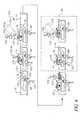
  • Figure 1 is a semi-diagrammatical view of an embodiment of the production system which performs an embodiment of the method.
  • Figure 2 is a semi-diagrammatical cross-sectional view of a one-time-use camera produced by the method of Figure 1.
  • Figure 3 is a semi-diagrammatical view of the transporter of the production system of Figure 1.
  • Figure 4 is an enlarged semi-diagrammatical view of some steps of the first and second stages of the embodiment of the method of Figure 1.
  • Figure 5 is an enlarged, partial semi-diagrammatical view of another embodiment of the system having a modified unloading portion which performs another embodiment of the method.
  • Figure 6 is an enlarged semi-diagrammatical view of some steps of the second and third stages of the method of Figure 5.
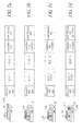
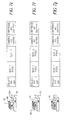
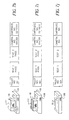
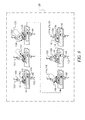
  • Figures 7a-7j are semi-diagrammatical views of a pallet and camera frame assembly and corresponding look-up table entries at different steps of the method of Figure 1.
  • Figure 8 is an enlarged semi-diagrammatical view of some steps of the second stage of the embodiment of the method of Figure 1.
  • Figures 9a-9c are the same views as Figures 7e-7g, but show a defective camera.
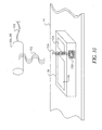
  • Figure 10 is a semi-diagrammatical perspective view of a portion of another embodiment of the production system. A pallet and reader are shown.
  • In the production method and system 10, cameras are assembled, loaded with film cartridges 22, and tested for defects. The system 10 has components divided among a number of different stations 12. A transporter 14 conveys pallets 16 carrying camera frame assemblies 18, from station 12 to station 12. The term "camera frame assembly" is used here to refer to a complete camera or an incomplete camera or subunit of a camera that will later be assembled with other parts to form a complete camera. At the stations 12 of the first portion 20 of the system 10, camera frame assemblies 18 and film cartridges 22 are loaded onto pallets 16. In the second portion 24 of the system 10, the transporter 14 extends through a light-tight enclosure, also referred to herein as a "dark enclosure 28". (The light tight enclosure 28 is indicated by a dashed line in some of the figures.) At the stations 12 of the second portion 24 of the system 10, film is prewound and the camera frame assemblies 18 are rendered light-tight. At the stations 12 of the third portion 26 of the system 10, the completed cameras are sorted. Camera frame assemblies 18 are tested for defects in one or more portions 20,24,26 of the system 10 and defective camera frame assemblies 18 are culled following the sorting. Camera frame assemblies 18 identified as being defective, while within the dark enclosure 28, cannot be removed unless provision is made to protect other camera frame assemblies 18 within the dark enclosure 28 from admission of light. This is undesirable, since it would add delay and complexity. Camera frame assemblies 18 identified as being defective, while within the dark enclosure 28, and, optionally, while in the first portion 20 of the system 10 are therefore left in the queue. Instead of being removed, pallets 16 bearing camera frame assemblies 18 having defects are indicated in a defect record 30 (illustrated in Figures 9a-9c) and are removed at the end of assembly. The pallets 16 after removal of cameras are returned to the first portion 20. This procedure is indicated, in the figures, by arrows 31,33 and can be provided by any conventional means, including manual transport of empty pallets.
    The method and system 10 are used for cameras in which a filmstrip 32, prewound into a roll 34, is advanced back into the canister 36 of a film cartridge 22 during use, by a film transport (illustrated as box 37 in Figure 2). Figure 2 illustrates one embodiment of a one-time-use camera 38. The camera 38 has a front cover 40, a back or back cover 42, and a frame unit 44 located between covers 40,42. During camera 38 use, a first film chamber 46 can contain a coreless film roll 34 or can have a film roll 34 held by a spool (not illustrated). A second film chamber 48, during use, holds the film cartridge 22. The end of the filmstrip 32 is attached to a cartridge spool 50 within the canister 36. A thumbwheel 51 is joined to the cartridge spool 50. The frame unit 44 defines a film path (indicated by arrow 52 in Figure 2) along which the photographic filmstrip 32 travels as the filmstrip is advanced during use. The film path extends from the first film chamber 46, across an intermediate section 54 to the second film chamber 48. The intermediate section 54 includes an exposure area to which light is directed by an exposure unit 56. The exposure unit 56 includes sub-components such as a baffle, a lens system, a shutter, and a shutter release (not separately illustrated). The camera 38 can include a variety of other well-known camera features. For example, the intermediate section 54 can include frame rails for supporting the film during camera use. Discrete camera constituents, such as, a flash system 47, a viewfinder, and a battery (not separately illustrated); can also be installed in the camera during assembly.
    The transporter 14 conveys the pallets 16 from station 12 to station 12. In the first portion 20 of the system 10, the transporter 14 can be linear or can be arranged in two or more branches 58. The transporter 14 combines the two or more branches 58 at an intersection 60. The use of multiple branches 58 accommodates differences in processing speed of different portions 20,24,26 of the system 10. The system 10 is illustrated and generally described herein in relation to an embodiment having two branches 58 in the first portion 20 and unbranched second and third portions 24,26. It will be understood that the number of branches 58 in the different portions 20,24,26 can be varied, in any combination, to meet the process speed limitations of particular embodiments.
    In the second portion 24 of the system 10, the filmstrips 32 are prewound out of the film cartridges 22 and into film rolls 34, within the dark enclosure 28. The camera frame assemblies 18 are light-tightly closed over the film rolls, transported out of the dark enclosure 28, and completed. The film 32 is protected, by the dark enclosure 28, from actinic light during film winding and closure of the camera frame assemblies 18. The method can be fully automated or can have one or more manual steps. The transporter 14 moves the pallets 16 from station 12 to station 12, but is otherwise not critical.
    Figure 3 illustrates one embodiment of the transporter 14. In the first portion 20 of the system 10 are a pair of spaced apart conveyer belts 62. Each belt 62 is driven by a motor 64. Motors 64 for conveyer belts 62 and other components are indicated by boxes in Figure 3. The two conveyer belts 62 lead into a low friction chute or table 66. Powered rollers 68 propel the pallets 16 along the chute 66 toward and then through the intersection 60. The table can have nonpowered rollers or skids or the like (not shown) to reduce friction and more easily allow for movement of the pallets 16 and can be inclined to provide a gravity assist.
    The intersection 60 of the first portion 20 of the transporter 14 delivers pallets 16 to a stub conveyer belt 70 within an entry section 72 of the dark enclosure 28. Outer and inner doors 74,76 (indicated by dashed lines) of the entry section 72 are alternately opened and closed to permit pallets 16 to pass through, and yet exclude light from the main section 78 of the dark enclosure 28. The stub conveyor belt 70 leads to a main conveyor belt 80 within the main chamber. The dark enclosure 28 has an exit chamber 82 beyond the main section 78. The exit chamber 82 includes a stub conveyer belt 70 and inner and outer doors 76,74 which function in the same manner as like features of the entry section 72. The intersection 60, stub conveyer belts 62 and a main conveyer belt 80 within the main section 78 of the dark enclosure 28, are all positioned close enough together for the pallets 16 to bridge gaps through which the doors 74,76 move (not shown).
    Beyond the dark enclosure 28, in the third portion 26 of the system 10, is a chute or table 84 that has a swingable gullet 86 that provides for selective movement of pallets 16 between a first outlet 88 for non-defective camera frame assemblies 18 and a second outlet 90 for defective cameras, as referred to herein as "culls". In the embodiment shown in Figure 3, a linear motor 64a swings the gullet 86 between the two different outlets 88,90. The chute 84 can operate by gravity or can have a powered roller or other propulsion device (not shown).
    The movement of the pallets 16 along the transporter 14 is coordinated as required by the components of the stations 12 and can be intermittent or continuous. If desired, pallets 16 can be located within stations 12 by stops 92. A stop is illustrated in Figure 3 for one of the stations 12 (indicated by a dashed box) by a swingable bar 92a and associated drive 94. Suitable components for the transporter 14 are well-known to those of skill in the art. The transporter 14 can also be simplified, is desired, by leaving out motors 64, and instead providing manual movement of the pallets 16 from station 12 to station 12, in all or only part of the system 10. For example, in the embodiment shown in Figure 3, the conveyers can be replaced by tables and the pallets can be moved manually from one station to another along the tables. Both chutes can be unpowered and can operate by gravity, with or without a manual assist.
    Referring now particularly to Figure 1, each of the stations 12, except at the ends, is illustrated as having an active component 96, a reader 98, and an tester 100. This is a matter of convenience in illustrating the system 10. The various components 96,98,100 are provided at the different stations 12 as necessary to meet system 10 requirements. Each of the components 96,98,100 can include an actuation mechanism (not illustrated), such as a retraction-extension system for moving the respective component between a non-use position, in which the component is clear of the transporter, and a use or active position, in which a pallet 16 in the respective station 12 is accessible to the component. The actuation mechanism can also include other parts, such as rotary or linear drives, for imparting motion to components or parts of the camera frame assemblies or film cartridges.
    Each of the components 96,98,100 is connected by a communication line 102 to a trunk 104 which then extends to a controller 106. The trunk 104 can be a wiring harness connecting each of the in individual components, or the trunk 104 can be a common line for multiplexed or networked signals. The controller 106 can be a programmable logic controller or personal computer.
    In the method, pallets 16 are placed on the transporter 14, as indicated by arrows 109. Camera frame assemblies 18, that is, incomplete camera bodies, are then placed on respective pallets 16. Film cartridges 22 are placed on the pallets 16 with the camera frame assemblies 18. The two streams of pallets 16 are then brought together at the intersection 60. The order of the pallets 16 leaving the intersection 60 can be indeterminate. In other words, pallets 16 need not be provided by the two branches 58 at the same rate and the rate for each branch 58 can vary with time. This is likely, for example, if the steps of the first portion 20 of the system 10 are done manually. After pallets 16 enter dark enclosure 28, the film cartridge 22 is placed in the camera frame assembly 18 and the film is prewound out of the cartridge 22. A back 42 is then placed over the camera frame assembly 18 light tightly closing the camera frame assembly 18. The pallets 16 then leave the dark enclosure 28.
    At each station 12, one or more parts are assembled and one or more functions are tested or both assembly and testing is performed. The pallets 16 each have a machine readable indicator 108, which uniquely identifies the individual pallet 16. The term "machine readable indicator" is inclusive of any form of information that can be detected without human intervention, including optical, magnetic, radio frequency, and tactile information. Symbols or alphanumeric indicators can be used, but it is generally more convenient to provide the indicator in the form of a pallet bar-code 108. Suitable pallet bar-code 108 symbologies and appropriate readers are well known to those of skill in the art.
    Referring now particularly to Figure 10, another type of indicator that can be used is a radio frequency identification transponder 150. The term "radio-frequency identification transponder" is used herein to refer to any of a class of compact radio receiver-transmitters which are powered by an ambient radio-frequency field. The transponder is accessed by modulating the field with an appropriate communication signal (indicated by wave pattern 152 in Figure 10) from a reader 98,98a, in the form of a radio frequency transmitter-receiver. The transponder reacts, responsive to the communication signal and supplies an identification number or alphanumeric sequence or other indicator as a radio-frequency transmission (indicated by wave pattern 154 in Figure 10). Radio-frequency identification transponders are widely available in a variety of forms. These devices include a non-volatile memory, such as an EEPROM (Electrically Erasable Programmable Read-Only Memory) semiconductor component integrally contained in the transponder. Stored in the non-volatile memory are encoded data. Particularly convenient are inlay transponders that have a substantially flat shape. The antenna for an inlay transponder is in the form of a conductive trace deposited on a non-conductive support. The antenna has the shape of a flat coil or the like. Leads for the antenna are also deposited, with non-conductive layers interposed as necessary. Memory and any control functions are provided by a chip mounted on the support and operatively connected through the leads to the antenna. Inlay transponders have been used as layers of identification tags and labels to provide encodements that are accessible at a distance. Inlay transponders of this type are marketed by Texas Instruments Incorporated, of Dallas, Texas, as Tag-it™ Inlays. Figure 10 illustrates a pallet bearing an inlay transponder.
    For convenience, pallet indicators are generally identified herein as "pallet bar-codes 108" and the reader 98 optically reads the pallet bar code, but it will be understood that other types of indicators and readers could also be used such as those shown in Figure 10.
    The pallet bar-codes 108 are read at some or, preferably, all of the stations 12. Information determined about the camera frame assembly 18 and film cartridge 22 carried by the pallet 16 is sent to the controller 106 and is associated with the pallet bar-code 108 for that pallet 16, in a memory unit (not separately illustrated) of the controller 106. For convenience, the collected information is referred to herein as a "table".
    The camera frame assemblies 18 are illustrated as bearing identifiers 110, in the form of bar-codes, at an early stage of the assembly process. Because the pallet bar-codes 108 are used to register information in the table, the camera identifiers 110 can be added whenever convenient. Defective cameras can be unnumbered, allowing continuous numbering of identifiers 110 of cameras packaged together for distribution. Monitoring is easier, since camera identifiers 110 can be provided in continuous blocks of numbers. The use of pallet bar-codes 108 also avoids any problems that could result from using film cartridge identifiers 112 to also identify cameras, such as possible confusion during reuse of film cartridges from defective cameras.
    The tabulated information about each pallet 16 is used in culling defective camera frame assemblies 18 at the completion of the process. This is a particularly advantageous approach, in that testing can be provided in the dark enclosure 28, without requiring access for culling of defective camera frame assemblies 18 at that time. Defective camera frame assemblies 18 can instead be tested for defects within the dark enclosure 28 and then be culled later after completing the assembly process. In the first portion 20 of the system 10, camera frame assemblies 18 can be tested and defective camera frame assemblies 18 can be easily removed, since it is easy to do so within the daylight environment. On the other hand, the first portion 20 of the system 10 can be simplified by eliminating the removal of defective camera frame assemblies 18. In this case, the camera frame assemblies 18 are tested, defects are recorded, and defective camera frame assemblies 18 are then allowed to continue through the assembly process for culling at the end. This approach also helps ensure the integrity of information in the controller. All pallets 16 enter and leave the system 10 only at the beginning and end, and all pallets 16 within the system 10 are continuously tracked in the table.
    Access to camera frame assemblies 18 within the dark enclosure 28 is necessarily limited by the requirement that the film be protected from actinic light. As earlier indicated, this limited access to the dark enclosure 28 is accommodated, in the case of culls, by removing defective camera frame assemblies 18 later, using information recorded in the table. The limited access can also be used to help ensure that one or more alteration units 114 are not bypassed. Referring to Figure 8, alteration units 114 are individual active components 96 or groups of active components that act only on defective camera frame assemblies 18 or act in a different manner on defective and non-defective camera frame assemblies 18. The actions of alteration units 114 modify the completed defective camera frame assemblies to be different than the completed defect-free camera frame assemblies and are initial steps in the reclamation of reusable parts of the defective camera frame assemblies. In the embodiments disclosed herein, an alteration unit 114 includes a camera printer 116 and a film cartridge rewinder 118.
    The printer 116 prints defect indicators 120 (shown in Figures 5-6) on the outsides of camera frame assemblies 18, for use in classifying defective camera frame assemblies 18 for recycling of usable parts and monitoring of production. The printer 116 can optionally print an identifier 112 of the film cassette in the camera, on the outside of the camera. The cassette identifier 112 can be human or machine readable and is illustrated as a bar code.
    The film cartridge rewinder 118 rewinds film 32 from a film roll 34 back into the film canister 36 of the cartridge 22. This rewinding is only done with defective camera frame assemblies 18. This occurs within the dark enclosure 28, thus when the defective camera frame assemblies 18 leave the dark enclosure 28, the defective camera frame assemblies 18 can be opened and the film cartridges 22 can be removed in daylight for later reuse. For Advanced Photo System film cartridges, the rewinder 118 can include an active light lock closer (not shown). A closer can also be provided as part of the camera frame assemblies or active light locks can be closed manually within the dark enclosure after rewinding.
    The operation of the printer 116 and rewinder 118 are illustrated in simplified form, in the figures. Referring now particularly to Figures 4-8, an empty pallet 16 is initially placed on the transporter 14 and pallet bar-code 108 on the pallet 16 is read. The pallet 16 has nests 124,126 (illustrated as recesses) for a camera frame assembly 18 and a film cartridge 22. An entry is created in the table in the controller 106, indicating the identity of the pallet 16. Entries are shown in the figures as words and numbers, but can be recorded in any form. Information can be compressed or encoded and absent entries can also be used to indicate default values. A camera frame assembly 18 is placed on the pallet 16 by a pick-and-place device 128. (A clamping tool and part of an arm of this active component are illustrated.) A pallet bar-code 108 on the camera frame assembly 18 is read and that information is entered in the table in association with the pallet 16 number, as shown in Figure 6b.
    Additional assembly operations can be performed at this time and tests undertaken. This is illustrated by a station 12a (shown in Figure 4) in which rotation of the thumbwheel 51 is checked. A rotatable disk 130 driven by a motor 132 is brought into contact with the edge of the thumbwheel 51 and rotation is monitored by a tester 100, such as an optical sensor. The disk 130 engages the rim of the thumbwheel 51. The disk 130 can be toothed complementary to the thumbwheel or knurled or otherwise configured to provide a positive engagement with the thumbwheel 51. Marks can be provided on the thumbwheel 51 to make it easier for the sensor 100a to detect movement of the thumbwheel 51. Motion can alternatively be detected by a change in the load on the motor 132. Suitable equipment to perform these functions is well known to those of skill in the art. A camera frame assembly 18 is considered defective, if the thumbwheel rotates with the application of a force that exceeds a predetermined value. The sensor 100a sends a signal to the controller 106, which records in the table an entry indicating whether the camera frame assembly 18 is acceptable or defective. (Test results are indicated in the table shown in Figures 7a-7j and 9a-9c, by the terms "Pass" and "Fail".)
    A film cartridge 22 is next placed on the pallet 16 by a put-and-place device 128. An identifier 112 on the film cartridge 22 is read at this time and that information is entered in the table, as shown in Figure 6d. The pallet 16 then enters the dark enclosure 28 and additional assembly and testing operations are undertaken.
    In the dark enclosure 28, the film cartridge 22 is placed in the camera frame assembly 18 by an installation device 134. The station 12 is illustrated in Figure 4, as also having a sensor 100 that detects whether the cartridge 22 is seated in the camera frame assembly 18. This test could provide a signal to the table in the controller 106, but is not illustrated as doing so in the figures. The installation device can be a simple pick-and-place device or can also provide additional functions, such as opening a light lock door of an Advanced Photo System 10™ film cartridge 22. These and other functions can also be provided by a combination of manual and automated stations.
    In the dark enclosure 28, assembly operations and testing are performed and the camera frame assembly 18 reaches the state, in which the leading portion 142 of the filmstrip 32 extends out of the canister 36. Type 135 (35 mm) film cartridges 22 are in this state, as manufactured. Advanced Photo System 10 film cartridges 22 reach this state after the light lock door is opened and the leading portion of the filmstrip 32 is thrust outward. The leading portion 142 is attached to a mandrel 144 and the film roll 34 is wound. Sensors 100 detect the presence and required motions of the filmstrip 32.
    The operation of the thumbwheel 51 is tested and test results are signalled to the controller 106, in the same manner as earlier described. There is a distinction in the two tests, in that the spool 50 of the film cartridge 22 is also tested for rotation in the second test. For this reason, it is preferred that the thumbwheel 51 be rotated, in this second test, only in the direction of thrusting the filmstrip 32 from the cartridge 22. The direction of rotation of the disk 130 is indicated by an arrow 136. The thumbwheel 51 can be rotated in either direction in the first test. In both cases, the camera frame assembly 18 does not have a functioning anti-backup mechanism. It is well known in the art to place an anti-backup mechanism on a later assembled part, such as a back cover 42, or to defeat a previously assembled anti-backup mechanism using a tool. The results of the test, indicated as "Test 2" in the figures, are signalled to the controller 106.
    Additional assembly steps and testing are undertaken to complete the camera. Figures 7f-7h illustrate prewinding of the filmstrip 32 out of the canister 36 of the film cartridge 22 and into a film roll 34 and installation of the back cover 42.
    Referring now particularly to Figure 6, the camera frame assemblies 18 are printed within the dark enclosure 28 by a print head 136 of the printer 116. An inkjet print head 136 on a movable arm 138 is illustrated, but any type of printer 116 can be used. Labels can also be individually printed separately then attached (not illustrated). The latter approach is useful with complexly shaped camera bodies. In any case, it is preferred that when the camera frame assemblies 18 leave the dark enclosure 28, defective camera frame assemblies 18 have printed defect indicators 120, such as codes for particular defects, as shown in Figure 5. The defect-free camera frame assemblies 18, in the embodiment shown in Figures 5-6 are printed with the identifier 112 of the film cartridge 22 before the camera frame assemblies 18 leave the dark enclosure 28. Defective camera frame assemblies 18 can be printed with film cartridge identifiers 112 in addition to defect indicators 120, but this is not useful and, is not preferred if there is any risk that the film cartridge indicator 112 could cause a mix-up of defective and defect-free camera frame assemblies 18. In the third portion 26 of the system 10, as shown in Figure 6, defective camera frame assemblies 18 are culled and defect-free camera frame assemblies 18 are sent onward for additional handling, such as inspection, packaging, and the like. In Figure 5, the output chute 84 delivers defect free camera frame assemblies 18 for further processing (indicated by arrow) and delivers defective camera frame assemblies 18 to a table 142 for manual sorting, reclamation of usable components, and disposal or recycling of remaining parts (indicated by arrow). In the embodiment shown in Figure 1, automated stations perform the same activities and defect indicators 120 are usable, but unimportant.
    Referring now to Figures 1-2 and 7a-9c, the filmstrip 32 of the film cartridge 22 is wound out of the canister in the second portion 24 of the system 10 in the dark enclosure 28. In doing so, a main part of the filmstrip 32 is wound into a film roll. The film roll is housed in the camera and is protected from light, in the finished camera, by the camera frame assembly 18. Film cartridges 22 can be reclaimed from defective camera frame assemblies 18, but the filmstrip 32 must first be rewound into the canister 36 without exposing the filmstrip 32 to actinic light. The film rewinder 118 rewinds the filmstrips 32 of only the defective camera frame assemblies 18. At a downstream station 12, the bar code of the pallet 16 is read and the value obtained is compared to the defect record 30, that is, a record in the table that indicates that the camera on a particular pallet 16 has one or more defects. If the pallet 16 is found in the defect record 30, then a quill 146 engages the spool 50 of the film cartridge 22 and the filmstrip 32 is rewound back into the canister 36. If the pallet 16 is not in the defect record 30, then the filmstrip 32 is not rewound. In any case, the camera is completed, including installing the back, and, optionally, printing cartridge 22 identifiers and/or defect indicators as earlier described.

    Claims (18)

    1. A delayed culling assembly method comprising the steps of:
      partially assembling a set of camera frame assemblies, each said camera frame assembly being disposed on a pallet, each said pallet having a unique machine-readable designator;
      during said partially assembling, loading a film unit into each said camera frame assembly;
      finding defects in one or more members of said set of camera frame assemblies;
      making a record of the respective said designators of said pallets bearing said camera frame assemblies having said defects;
      concluding assembly of said camera frame assemblies; and
      following said making and concluding, culling said camera frame assemblies on respective said pallets having said designators in said record.
    2. The method of claim 1 wherein said culling includes reading said designators and, following said reading, printing a defect marker on said camera frame assemblies on respective said pallets having said designators in said record.
    3. The method of claim 1 or 2 wherein each said film unit has a unique machine-readable identifier and said method further comprises finding a subset of said camera frame assemblies that are free of said defects and printing respective said identifiers on said subset of said camera frame assemblies.
    4. The method of claim 1, 2, or 3 wherein said film unit includes a filmstrip and a light-shield blocking light from said filmstrip and said method further comprises:
      prior to said concluding, clearing each said light-shield from at least part of the respective said filmstrip; and
      prior to said culling, restoring said light-shields of the respective said filmstrips of said camera frame assemblies on respective said pallets having said designators in said record; and
      during said clearing, finding, making, concluding, and restoring, continuously protecting said filmstrips from actinic light independent of respective said light-shields.
    5. A production method for camera frame assemblies having light-sensitive filmstrips, said method comprising the steps of:
      partially assembling a plurality of camera frame assemblies;
      during said partially assembling, associating a film unit with each said camera frame assembly, said film unit including a filmstrip and a light-shield blocking light from said filmstrip;
      loading said film units into respective said camera frame assemblies,
      clearing each said light-shield from at least part of the respective said filmstrip;
      following said clearing, concluding assembly of the respective said camera frame assemblies;
      identifying ones of said camera frame assemblies having defects;
      following said clearing and identifying, restoring said light-shields of the respective said filmstrips of said camera frame assemblies having defects; and
      during said clearing, identifying, and restoring, continuously protecting said filmstrips from actinic light independent of respective said light-shields.
    6. The method of claim 5 further comprising printing a defect marker on said camera frame assemblies having defects; and continuously keeping each said camera frame assembly in a light-tight enclosure during said clearing, concluding, identifying, restoring, and printing.
    7. The method of claim 5 or 6 wherein said clearing further comprises prewinding said filmstrip into a film roll and said restoring further comprises rewinding said filmstrip; and said method further comprises continuously keeping each said camera frame assembly in a light-tight enclosure during said winding, concluding, identifying, and rewinding.
    8. The method of claim 5, 6, or 7 further comprising holding said camera frame assemblies on individual pallets during said partially assembling, associating, loading, clearing, concluding, identifying, restoring, and protecting; wherein each said pallet has a unique machine-readable designator and said identifying further comprises illuminating said designators with non-actinic radiation and detecting returning non-actinic radiation modulated by respective said designators.
    9. The method of claim 5, 6, 7, or 8 further comprising culling said camera frame assemblies having defects following said restoring.
    10. The method of claim 1, 2, 3, 4, 5, 6, 7, 8, or 9 wherein said partially assembling further comprises preparing first and second sequences of said camera frame assemblies in tandem and combining said first and second sequences in indeterminate order.
    11. A production system for producing camera frame assemblies loaded with prewound filmstrips, said apparatus comprising:
      a set of pallets, each said pallet being capable of bearing an individual said camera frame assembly;
      a plurality of assembly devices, said assembly devices receiving said pallets and together assembling said camera frame assemblies on said pallets and loading film cartridges into said camera frame assemblies;
      a series of inspectors disposed in operative relation to a plurality of said assembly devices, said inspectors identifying ones of said camera frame assemblies having defects and ones of said camera frame assemblies free of said defects;
      a alteration unit receiving each of said pallets, said alteration unit preparing said film rolls of said camera frame assemblies having defects for culling, said alteration unit transmitting said camera frame assemblies free of said defects without said preparing; and
      a transporter moving said pallets in sequence by said assembly devices, said film winder, and then said film rewinder.
    12. The system of claim 11 wherein each said pallet has a unique machine-readable designator, said inspectors each have a reader that reads respective designators of said pallets bearing said camera frame assemblies having defects, and said alteration unit has a reader that reads said designators of each said pallet.
    13. The system of claim 12 wherein each said pallet includes a radio-frequency transponder supplying the respective said machine-readable designator.
    14. The system of claim 11, 12, or 13 wherein said pallets on said transporter are subject to resequencing before said alteration unit.
    15. The system of claim 11, 12, 13, or 14 wherein said alteration unit further comprises a film rewinder receiving each of said pallets, said film rewinder rewinding said film rolls of said camera frame assemblies having defects back into respective said cartridges, said film rewinder transmitting said camera frame assemblies free of said defects without rewinding.
    16. The system of claim 15 further comprising an enclosure protecting said film rolls from actinic radiation in said film winder and film rewinder.
    17. The system of claim 11, 12, 13, 14, 15, or 16 wherein said alteration unit further comprises a printer receiving each of said pallets, said printer printing defect markers on said camera frame assemblies having defects.
    18. The system of claim 17 further comprising a reader disposed to read identifiers printed on said film cartridges, and wherein said reader is operatively connected to said printer, and said printer prints said identifiers of respective said film cartridges on said camera frame assemblies free of said defects.
    EP01202123A 2000-06-15 2001-06-05 Apparatus and method of loading a film in a reusable camera wherein culling of defective cameras is delayed Withdrawn EP1168056A3 (en)

    Applications Claiming Priority (2)

    Application Number Priority Date Filing Date Title
    US09/594,881 US6438323B1 (en) 2000-06-15 2000-06-15 Camera film loading with delayed culling of defective cameras
    US594881 2000-06-15

    Publications (2)

    Publication Number Publication Date
    EP1168056A2 true EP1168056A2 (en) 2002-01-02
    EP1168056A3 EP1168056A3 (en) 2004-01-07

    Family

    ID=24380801

    Family Applications (1)

    Application Number Title Priority Date Filing Date
    EP01202123A Withdrawn EP1168056A3 (en) 2000-06-15 2001-06-05 Apparatus and method of loading a film in a reusable camera wherein culling of defective cameras is delayed

    Country Status (3)

    Country Link
    US (1) US6438323B1 (en)
    EP (1) EP1168056A3 (en)
    JP (1) JP2002049132A (en)

    Families Citing this family (17)

    * Cited by examiner, † Cited by third party
    Publication number Priority date Publication date Assignee Title
    DE10034606B4 (en) * 2000-07-20 2004-02-26 Stefan Gleis Method for providing manufacturing-related data in a series production of manufacturing objects, in particular motor vehicles
    US7254878B2 (en) * 2001-11-28 2007-08-14 Fujifilm Corporation Apparatus for and method of manufacturing film
    US7006764B2 (en) * 2002-11-12 2006-02-28 Eastman Kodak Company User interface for controlling cropping in electronic camera
    US6907194B2 (en) 2002-11-12 2005-06-14 Eastman Kodak Company Camera having continuously cropping viewfinder
    US7561793B2 (en) * 2002-11-12 2009-07-14 Eastman Kodak Company User interface for controlling cropping in electronic camera
    US7206022B2 (en) * 2002-11-25 2007-04-17 Eastman Kodak Company Camera system with eye monitoring
    US7319780B2 (en) * 2002-11-25 2008-01-15 Eastman Kodak Company Imaging method and system for health monitoring and personal security
    US7046924B2 (en) * 2002-11-25 2006-05-16 Eastman Kodak Company Method and computer program product for determining an area of importance in an image using eye monitoring information
    US7233684B2 (en) * 2002-11-25 2007-06-19 Eastman Kodak Company Imaging method and system using affective information
    US20040113939A1 (en) * 2002-12-11 2004-06-17 Eastman Kodak Company Adaptive display system
    US7327890B2 (en) * 2002-12-20 2008-02-05 Eastman Kodak Company Imaging method and system for determining an area of importance in an archival image
    US20050134719A1 (en) * 2003-12-23 2005-06-23 Eastman Kodak Company Display device with automatic area of importance display
    US7369100B2 (en) * 2004-03-04 2008-05-06 Eastman Kodak Company Display system and method with multi-person presentation function
    US8659619B2 (en) 2004-03-26 2014-02-25 Intellectual Ventures Fund 83 Llc Display device and method for determining an area of importance in an original image
    US20060125928A1 (en) * 2004-12-10 2006-06-15 Eastman Kodak Company Scene and user image capture device and method
    DE102005036243A1 (en) * 2005-08-02 2007-02-08 Wilhelm Karmann Gmbh Production of convertible roofs
    US7697827B2 (en) 2005-10-17 2010-04-13 Konicek Jeffrey C User-friendlier interfaces for a camera

    Family Cites Families (20)

    * Cited by examiner, † Cited by third party
    Publication number Priority date Publication date Assignee Title
    US3787954A (en) 1971-03-15 1974-01-29 Eastman Kodak Co Scroll winding and loading method
    US3780961A (en) 1971-05-13 1973-12-25 Eastman Kodak Co Controls for spooling apparatus
    US3724162A (en) 1971-11-23 1973-04-03 Eastman Kodak Co Misaligned end cap detecting mechanism for a capping device
    US3802052A (en) 1973-01-12 1974-04-09 Eastman Kodak Co Detecting mechanism for detecting a missing end cap of a film
    GB2049994B (en) 1979-05-21 1983-08-03 Rca Corp Method for assembly in a crt
    JPS59143841A (en) 1983-02-03 1984-08-17 Fuji Photo Film Co Ltd Winding method and device for film
    US4890715A (en) 1984-02-06 1990-01-02 Walter Sticht Method of and a device for coding workpiece carriers in a production plant
    DE69315286T2 (en) 1992-09-10 1998-04-23 Konishiroku Photo Ind Manufacturing method for a photosensitive film cassette
    US5250979A (en) 1992-11-03 1993-10-05 Eastman Kodak Company Technique suited for use in fixed focus cameras for improving image quality for non-standard display sizes and/or different focal length photographing modes
    JP3036718B2 (en) 1993-06-18 2000-04-24 富士写真フイルム株式会社 Film unit with lens
    DE69433228T2 (en) * 1993-12-14 2004-05-06 Fuji Photo Film Co., Ltd., Minami-Ashigara Electronic test device for a flash unit
    EP0685758B1 (en) 1994-05-24 2000-08-23 Fuji Photo Film Co., Ltd. Apparatus for assembling photo film cassette
    US5568715A (en) 1994-05-31 1996-10-29 Johnson & Johnson Vision Products, Inc. Automated inspection system with transport and ejector conveyor
    US5555504A (en) * 1994-06-10 1996-09-10 Johnson & Johnson Vision Products, Inc. Production line tracking and quality control system
    JPH0843902A (en) 1994-07-26 1996-02-16 Konica Corp Camera integrated with film
    JPH10148915A (en) 1996-11-21 1998-06-02 Konica Corp Device and method of producing film unit with lens
    JPH10171074A (en) 1996-12-12 1998-06-26 Fuji Photo Film Co Ltd Production of film unit with lens
    US5765042A (en) 1997-01-10 1998-06-09 Eastman Kodak Company One-time-use camera with matching indicia on camera exterior and film cassette
    JP3773142B2 (en) * 1997-05-01 2006-05-10 富士写真フイルム株式会社 Manufacturing method and apparatus for film unit with lens
    EP0965882B1 (en) * 1998-06-09 2004-12-01 Fuji Photo Film Co., Ltd. Method of controlling production of a lens-fitted photo film unit

    Also Published As

    Publication number Publication date
    EP1168056A3 (en) 2004-01-07
    JP2002049132A (en) 2002-02-15
    US6438323B1 (en) 2002-08-20

    Similar Documents

    Publication Publication Date Title
    US6438323B1 (en) Camera film loading with delayed culling of defective cameras
    US6205060B1 (en) Method of controlling a production process and recycle of photo film cartridge or lens-fitted photo film unit
    EP0829764A1 (en) Printing paper information reading apparatus
    US5426481A (en) Order finishing
    US3766525A (en) Apparatus for manipulating receptacles of exposed customer films
    JP3555672B2 (en) Photo processing equipment
    JP3103455B2 (en) Photosensitive material handling equipment
    JP2000066340A (en) Method for controlling production of photographic film cartridge
    JP3255737B2 (en) Method of reusing batteries and parts of used film unit with lens
    JP2875766B2 (en) Order coding method and apparatus in photo processing
    JP3670363B2 (en) Cartridge chucking method
    US6025903A (en) Piece negative feeding apparatus
    JP3583211B2 (en) Film bonding equipment
    JP3583210B2 (en) How to handle cartridges
    JPH09120143A (en) Film rewinding device
    JP3653049B2 (en) Photo film inspection method
    EP0890871B1 (en) Method and apparatus for judging an error in reading data recorded on a photographic film
    JPH09120144A (en) Film rewinding device
    JPH08334866A (en) Method for recording inspection history of recycled parts for film unit with lens
    JPH0519439A (en) Cartridge housing container for photograph processing device
    JPH09120149A (en) Cartridge identifying/positioning device
    JPH06337502A (en) Film unit with lens and automatic photographic processor
    JPH09120140A (en) Chucking device for cartridge
    JPH1048757A (en) Photographic processing method
    JPH08108326A (en) Method for controlling manufacturing process of photographic film cartridge

    Legal Events

    Date Code Title Description
    PUAI Public reference made under article 153(3) epc to a published international application that has entered the european phase

    Free format text: ORIGINAL CODE: 0009012

    AK Designated contracting states

    Kind code of ref document: A2

    Designated state(s): AT BE CH CY DE DK ES FI FR GB GR IE IT LI LU MC NL PT SE TR

    AX Request for extension of the european patent

    Free format text: AL;LT;LV;MK;RO;SI

    PUAL Search report despatched

    Free format text: ORIGINAL CODE: 0009013

    AK Designated contracting states

    Kind code of ref document: A3

    Designated state(s): AT BE CH CY DE DK ES FI FR GB GR IE IT LI LU MC NL PT SE TR

    AX Request for extension of the european patent

    Extension state: AL LT LV MK RO SI

    RIC1 Information provided on ipc code assigned before grant

    Ipc: 7G 05B 19/418 B

    Ipc: 7G 03B 19/04 B

    Ipc: 7G 03B 43/00 A

    AKX Designation fees paid
    REG Reference to a national code

    Ref country code: DE

    Ref legal event code: 8566

    STAA Information on the status of an ep patent application or granted ep patent

    Free format text: STATUS: THE APPLICATION IS DEEMED TO BE WITHDRAWN

    18D Application deemed to be withdrawn

    Effective date: 20040708