BACKGROUND OF THE INVENTION
Field of the Invention
The present invention relates to a projection
optical system, for example, provided in a projection
exposure apparatus that is used on occasion of
photolithography when manufacturing semiconductor
elements, display elements such as liquid crystal
display and plasma display, and micromachine etc.
such as microdevices. It also relates to a
manufacturing method of the projection optical system
and to a projection exposure apparatus.
Related Background Art
In a photolithographic process used for
manufacturing semiconductor elements and the like,
a projection exposure apparatus is used to expose,
through a projection optical system, the image of the
pattern of the reticle as mask onto a substrate, i.e.
a wafer (or glass plate, etc.) on which is applied
a photo resist. As the degree of integration of
semiconductor elements and so on continue to improve,
a demand for a resolving power of the projection
optical system in a projection exposure apparatus
becomes even greater. In order to meet the demand,
shortening the wavelength of the illuminating light
(exposure light) for exposure and increasing the
numerical aperture (NA) of the projection optical
system have been performed. However, when exposure
light wavelengths are shortened, varieties of glass
material can be used practically are becoming fewer,
due to the light absorption. In particular, when the
exposure light wavelength becomes vacuum ultraviolet
(VUV), approximately 200 nm or shorter, the glass
materials that can be used under current conditions
becomes limited to, for example, synthetic silica,
fluorite (CaF2), and magnesium fluoride (MgF2). The
problem of how to compensate chromatic aberration
therefore happens.
Even so, there has been progress made in the
practical application of the refractive system in
projection optical systems using an ArF excimer laser
(wavelength 193nm) as exposure light. However, when
the exposure light wavelength fall to 180 nm or
shorter as with an F2 laser (wavelength 157 nm), it
is difficult to put projection optical systems into
practical use with a refractive system, but
expectations are rising for catadioptric systems
providing a reflective member as means for
compensating chromatic aberration. In this regard,
since it is known that fluorite has sufficient
transmissivity up to approximately 100 nm, it may be
used as a refractive member up to this range. A
catadioptric optical system is realized by assembling
a refractive member made of fluorite (calcium
fluoride) and a reflective member.
A number of types of catadioptric optical
systems have already been proposed. Of these,
cptical systems that have the center portion of the
aperture stop shielded are considered most
influential since, by using a reflective surface
having two or more faces, all of the optical elements
can be disposed in an upright cylindrical shape along
a single the optical axis without requiring an optical
path deflection member, Moreover, since the image of
an object in the optical axis can be formed on an image
plane, they also include the advantage of chromatic
aberration being able to be compensated in a wide
exposure field with only a relatively low number of
optical elements. Of these, optical systems that
form an intermediate image partway through the
optical system, for example, such as the optical
system disclosed in U.S. Patent No. 5,650,877, are
quite effective in terms of throughput and ease in
manufacturing in comparison with optical systems that
have an optical member such as a semi-transparent
mirror disposed partway, and therefore have no
intermediate image formed, greatly reduced light
intensity, and increased danger of large-scale flares
ceveloping. This type of conventional technology is
cited in, for example, U.S. Patent Nos. 5,717,518 and
5,488,229.
In addition, since the optical absorption rate
of the exposure light increases due to oxygen and
carbon dioxide when exposure light is approximately
200 nm or shorter, in order to increase the
illuminance on the wafer, it is necessary to replace
the air within the lens barrel of the projection
optical system with a purge gas such as nitrogen gas
(N2) or helium gas (He), which have high
transmissivity for wavelengths of approximately 200
nm or shorter. To this end, various purge gas supply
mechanisms have conventionally been proposed.
SUMMARY OF THE INVENTION
The present invention was devised as a result
of the following findings by the inventors. As shown
with the above, in cases where an exposure light
belonging to vacuum ultraviolet region is used, a
catadioptric optical system is an excellent
projection optical system. However, with the
catadioptric optical system, even if a virtually
upright cylinder, the entire length is quite long in
comparison with a refractive system, and becomes
difficult to support with a single lens barrel.
Furthermore, with the catadioptric optical system in
U.S. Patent No. 5,717,518, as it can be seen from the
fact that the material for the reflective members is
large compared to the glass used for the refractive
members, with the catadioptric optical system, it is
often the case that the reflective members (material)
must be made larger than the refractive members
(glass). In such cases, if a single lens-barrel with
a relatively small refractive member and a relatively
large reflective member are supported as a single body,
the configuration of that lens barrel becomes
complicated, and the stable support of that lens
barrel becomes difficult. Moreover, there are
problems with production costs becoming high with
projection optical systems since it takes time to
perform the assembly adjustment of that lens barrel
and all of the optical elements.
The method for holding the optical element group
that comprises catadioptric optical system not by a
single lens-barrel, but divided between a plurality
of divided lens-barrels is also considered. However,
in cases where these optical elements are simply
divided into a plurality of groups and held by a
plurality of divided lens-barrels, there require the
divided lens-barrels with partially extremely
complex structures, and also, fears are entertained
as to complex processes of assembly adjustment such
as aligning the respective axes of each divided
lens-barrel to each other.
Furthermore, since there is a danger of the
positional relationship between optical elements
that are held by different divided lens-barrels
fluctuating relative to set values by simply holding
a plurality of divided lens-barrels, there is a danger
of an increase in contributing factors for the
development of aberrations. In cases where a
plurality of divided lens-barrels are used, there
require positioning, for example, that suppresses the
development of aberrations .
Moreover, in the projection exposure apparatus
using vacuum ultraviolet light having wavelengths of
approximately 200 nm or less as exposure light, when
a purge gas is flowed through the optical path inside
of projection optical system, if those lens barrels
are configured from a plurality of divided
lens-barrels, then stagnancy develops in the flow of
purge gas at the boundaries of the divided
lens-barrels, and there is a danger that the density
of light absorbing substances, such as oxygen, may
not sufficiently decrease. In particular, in a
projection exposure apparatus using light of a
wavelength of 170 nm or shorter, for example F2 laser
light (157 nm wavelength) as exposure light, since
the permissible value of the residual density of the
light absorbing substances is lowered, if a divided
lens-barrel type is simply adopted, there is a danger
that the residual density of the light absorbing
substances may not fall below the permissible value.
An object of the present invention is to provide
a projection optical system capable of obtaining high
optical performance, a manufacturing method thereof,
and a projection exposure apparatus in which it is
included.
Another object of the present invention is to
provide, in addition to the above objects, a
projection optical system that includes a
catadioptric optical system having simple assembly
adjustment, a manufacturing method thereof, and a
projection exposure apparatus in which it is
included.
Yet another object of the present invention is
to provide, in addition to the above objects, a
projection optical system that includes a
catadioptric optical system that is capable of
adjusting the state of the optical elements, a
manufacturing method thereof, and a projection
exposure apparatus in which it is included.
Yet another object of the present invention is
to provide, in addition to the above objects, a
projection optical system that includes a
catadioptric optical system capable of maintaining
a stable positional relationship between a plurality
of optical elements, a manufacturing method thereof,
and a projection exposure apparatus in which it is
included.
Yet another object of the present invention is
to provide, in addition to the above objects, a
projection optical system capable of supplying a
high-purity purge gas and a projection exposure
apparatus in which it is included.
An aspect of the present invention is a
projection optical system forming an image of an
object in a first plane onto a second plane
comprising, an optical element group including at
least one refractive member and a plurality of
reflective members , and a plurality of lens-barrel
units holding the optical element group divided into
a plurality of groupings, wherein the plurality of
reflective members is all held by one lens-barrel unit
of the plurality of lens-barrels units.
Lens-barrel units hold an imaging optical
system for forming an image (for example, an
intermediate image or final image), and are
configured from, for example, a plurality of divided
lens-barrels, Each of the lens-barrel units has a
mechanism to adjust the state of the imaging optical
system. In the following, divided lens-barrels have
the same meaning as lens-barrel units.
An aspect of the present invention is that it
aims at making the amount of aberrations that are
generated in cases where the position of the optical
elements shifts from a designed position, higher in
the reflective members than in the refractive members.
According to an aspect of the present invention, since
all of a plurality of reflective members is held in
one lens-barrel unit, the relative positional
relationship of the plurality of reflective members
can be maintained in a nearly stable state. Also,
even if the lens-barrel unit holding the reflective
members is displaced due to vibrations, for example,
if the lens-barrel unit is thought of as a reference,
since it is the same value as the only displaced
lens-barrel unit holding only another refractive
member, the entire amount of generated aberration is
suppressed and high optical performance can be
obtained.
In this case, it is preferable that the partial
optical element group forming an intermediate image
on a third plane between the first plane and the
second plane, wherein the partial optical element
group is integrally held by one lens-barrel unit of
the plurality of lens-barrel units. When an
intermediate image is formed as such, the outer
diameter of the optical elements both before and after
the intermediate image may vary greatly. At this time,
by having the partial optical group that forms the
intermediate image be held by one lens-barrel unit,
the partial optical element group can be easily and
stably held.
Furthermore, as an example, that optical
element group is disposed along a single the optical
axis. Through such configuration in a vertical
barrel, the entire configuration of the lens barrel
becomes smaller, and that optical element group can
be stably held. It is noted here that, as an another
example, that optical element group may include a
first partial optical element group disposed along
a first optical axis, a second partial optical element
group disposed along a second optical axis which
extends in a direction that intersects the first
optical axis, and is optically connected to the first
partial optical element group, and a third partial
optical element group disposed along a third optical
axis which extends in the same direction as the first
optical axis, and is optically connected to the second
partial optical element group, Here a second optical
axis, which is approximately orthogonal to the first
optical axis, is included in a second optical axis
that extends along the direction that intersects a
first optical axis. A third optical axis that is
approximately parallel to first optical axis is
included in a third optical axis that extends in the
same direction as first optical axis.
Furthermore, it is preferable that the
plurality of lens-barrel units be supported
independent of each other. As a result of this, the
assembly adjustment is simplified.
Furthermore, it is preferable that at least one
of said plurality of lens-barrel units, has an
adjustment mechanism to adjust a predetermined state
of optical elements respectively held therein. By
adjusting the predetermined state (positioning of the
optical axis direction, the position of the direction
of the two axes within the plane that is orthogonal
to the optical axis (decentering adjustment), and the
tilt angle around the two axes) of those optical
elements, the magnification and predetermined
imaging performance, such as aberrations, of that
projection optical system can be compensated,
Furthermore, it is preferable that at least one
of the plurality of lens-barrel units further
comprising a plurality of holding blocks which hold
one or a plurality of optical elements, wherein the
plurality of holding blocks have an adjustment
mechanism to adjust the state of optical elements
respectively held therein.
Furthermore, it is preferable that at least one
of the plurality of lens-barrel units be detachable.
An aspect of the present invention, as an example,
uses an illumination light with wavelengths of 200
nm or shorter, preferably supplies a purge gas through
which the illumination light passes to inside the
projection optical system. Since each projection
optical system of the present invention comprises a
plurality of lens-barrel units or a plurality of
holding blocks that are built up (connected),
assembly adjustment is simplified. Moreover, since
these lens-barrel units and holding block can be
configured with a high level of gas-tightness, a
high-purity purge gas can be supplied into those
projection optical systems. The illuminance of the
illumination light becomes high and a high throughput
can be accordingly obtained for the exposure process.
It is preferable that there be provided a
plurality of vents (openings) in the part (lens mount,
etc.) that holds each optical element (refractive
member, reflective member) within each lens-barrel
unit or each holding block as a porous structure.
Furthermore, a holding block that holds, for example,
a relatively large reflective member, may be
supported by a frame mechanism having high
ventilation. By having these mechanisms, there is no
settlement from the purge gas, and as a result it is
possible to reduce the residual density of impurities
(light absorbing substances) within the projection
optical system.
Another aspect of the present invention is a
projection optical system comprising, an optical
element group including first and second optical
element sub-groups, and forming an image of a
predetermined magnification of an object in a first
plane onto a second plane , a first lens-barrel unit
integrally holding the first optical element
sub-group as a single body along a first optical axis,
and a second lens-barrel unit integrally holding the
second optical element sub-group as a single body
along a second optical axis that is coaxis with the
first optical axis, wherein the first lens-barrel
unit is held in a position at a plane that is orthogonal
to the first optical axis and that passes through a
point divides a line, along said first optical axis,
between an object point and an image point relative
to the first
sub optical element group by 1 : β1 (where β1 is a
real number other than zero), or in a position near
the plane, and the second lens-barrel unit is held
in a position at a plane that is orthogonal to the
second optical axis and that passes through a point
divides a line, along said second optical axis,
between an object point and an image point relative
to the second sub optical element group by 1 : β2
(where β2 is a real number other than zero), or in
a position near said plane.
According to another aspect of the present
invention, because each lens-barrel unit is
independently supported relative to each other,
assembly adjustment is simplified. Moreover, even
if first lens-barrel unit and second lens-barrel
unit are tilted, the respective image shift hardly
occurs. When used in a projection exposure apparatus,
even if lens-barrel unit is displaced because of the
affect of vibrations of the stage system and so on,
high optical performance can always be obtained.
This aspect can also be used as a limiting factor of
an aspect of the present invention above.
Yet another aspect of the present invention is
a projection optical system which forms an image of
an object in a first plane onto a second plane,
comprising, an optical element group having a
plurality of aspherical surfaces, and a
plurality of holding blocks holding the optical
element group in a plurality of groupings, wherein
the number of the plurality of holding blocks is equal
to or greater than the number of the aspherical
surfaces.
When assembling the projection optical system
according to another aspect of the present invention,
there may be a case where several µm of decentering
remains in each optical element where an aspherical
surface is formed. Due to such decentering of the
aspherical surface, a high order decentered
aberration occurs. For example by performing
decentering adjustment when successively integrating,
or by providing an decentering adjustment mechanism
in each holding block, the number of holding blocks
is kept equal to or greater than the number of
aspherical surfaces, it is possible to compensate
that high-order decentered aberration and obtain high
optical performance.
In this case, when those optical element groups
have a plurality of reflective members , it is
preferable that this plurality of reflective members
be held in holding blocks that are different from
each other. When the position of the reflecting
members is off a designed position, a large aberration
compared to the reflective member occurs. When a
plurality of reflective members are provided, it is
possible to minimize aberration by holding each
reflecting member in a different holding block and,
for example, adjusting the relative position when
integrating these holding blocks, or having a
mechanism that can fine tune the relative position
of the reflecting lens. This aspect can also be used
as a restriction of an aspect of the present invention
above.
Yet another aspect of the present invention is
a projection optical system which forms an image of
an object in a first plane onto a second plane,
comprising, an optical element group, a plurality of
lens-barrel units , which hold said optical element
group in a plurality of groupings, and frame from
which at least one lens-barrel unit of said plurality
of lens-barrel units is held so as to hang down.
By supporting the lens-barrel unit so as to hang
down in this manner, it is possible to provide
constant, stable support to the lens-barrel unit and
the optical elements that are held therein, and
maintain high optical performance. This aspect can
also be used as a restriction of an aspect of the
present invention above.
Yet another aspect of the present invention is
a projection optical system forming an image of an
object in a first plane onto a second plane by using
light with wavelengths of 200 nm or shorter,
comprising, at least two refractive members disposed
in the optical path of the light, at least two
lens-barrel units aligning the at least two
refractive members, a pipeline being connected to at
least one lens-barrel unit of the at least two
lens-barrel units and supplying purge gas through
which the light can pass within the space between the
at least two refractive members, and at least two
holding units being included in each of the at least
two lens-barrel units and holding each of the at least
two refractive members, wherein the at least two
holding units having openings to allow the purge gas
to pass through.
By having these mechanisms, there is no
settlement from the purge gas, and as a result it is
possible to reduce the residual density of impurities
(light absorbing substances) in the projection
optical system. Not only is this aspect a
catadioptric projection optical system, but it can
also be suited for a dioptric optical system. In this
aspect, it is preferable that it has light of a
wavelength of equal to 160 nm or shorter. This aspect
can also be used as a restriction of an aspect of the
present invention.
Yet another aspect of the present invention is
a projection optical system provided in a projection
exposure apparatus, comprising, an imaging optical
system including all of a plurality of reflective
members which are structural components of the
projection optical system, another imaging optical
system including at least one refractive member which
is a structural component of the projection optical
system and not including a reflective member which
is a structural component of the projection optical
system, a lens-barrel unit holding the imaging
optical system, and another lens-barrel unit holding
the another imaging optical system.
The same things can be said as the aspects of
the present invention described above accordingly.
A lens-barrel unit comprises a plurality of divided
lens-barrels, which include a mechanism for adjusting
the state of imaging optical systems, and the other
lens-barrel unit can be comprised of a plurality of
divided lens-barrels, which includes a mechanism for
adjusting the state of the other imaging optical
system. Furthermore, each of the plurality of
reflective members can be held by a divided
lens-barrel that is different from the others of a
plurality of divided lens-barrels, which forms a
lens-barrel unit. This aspect can also be used as a
restriction of an aspect of the present invention
above.
Another aspect of the present invention is a
method of manufacturing a projection optical system
which comprises an optical element group having at
least one refractive member and a plurality of
reflective members, and a plurality of lens-barrel
units holding the optical element group as a
plurality of groupings, the method of manufacturing
a projection optical system comprising, a first step
of pre-setting a predetermined lens-barrel unit of
the plurality of lens-barrel units to be detachable,
putting together a lens-barrel unit to be adjusted
at the position of the predetermined lens-barrel unit
of a first projection optical system that is already
completed as the projection optical system, and
performing adjustment on the lens-barrel unit to be
adjusted while measuring optical characteristics of
the first projection optical system, and a second step
of building up a second projection optical system by
an adjusted lens-barrel unit on which adjustment is
performed in the first step and lens-barrel units
other than this, and performing adjustment of the
second projection optical system using the adjusted
lens-barrel unit as a standard.
With the manufacturing method of a projection
optical system according to yet another aspect of the
present invention, when manufacturing a plurality of
projection optical systems in parallel, for example,
it is possible to adjust lens barrel unit of the next
projection optical system in only a short time by
using projection optical system, which has completed
assembly adjustment. Thereby, the assembly
adjustment time can be shortened as a whole.
Yet another aspect of the present invention is
a method of manufacturing a projection optical system
which comprises an optical element group including
at least one refractive member and at least one
reflective member, a plurality of lens-barrel units
holding the optical element group as a plurality of
groupings, a holding block being a component of at
least one lens-barrel unit of the plurality of
lens-barrel units and holding at least one optical
element, wherein the holding block is adjustable in
at least one of relative orientation and relative
position to the lens-barrel unit including the
holding block as structural component , and at least
one entire lens-barrel unit of the plurality of
lens-barrel units is adjustable, the method
comprising the step of; a first step of adjusting the
plurality of lens-barrel units relative to each
other; and a second step of adjusting the at least
one of the relative orientation and the relative
position of the holding block, so as to adjust
residual aberrations, after the first step.
By performing adjustment in this manner,
fine-tuning can be performed on large and small
aberrations, and it is possible to manufacture the
projection optical system that has optical
performance nearly equal that of the designs.
Yet another aspect of the present invention is
a projection exposure apparatus, which comprises the
projection optical system of the present invention
mentioned above and which projects an image of a
projection original disposed on the first plane onto
a workpiece, with the projection optical system. By
using the projection optical system of the present
invention, the assembly adjustment of the entire
apparatus becomes easy and the manufacturing cost can
be reduced.
Yet another aspect of the present invention is
a projection exposure method, which projects an image
of a projection original disposed on the first plane
onto a workpiece, with the projection optical system
of the present invention mentioned above. By using
the projection optical system of the present
invention, the assembly adjustment of the entire
apparatus becomes easy and the manufacturing cost can
be reduced.
The present invention will be more fully
understood from the detailed description given herein
below and the accompanying drawings, which are given
by way of illustration only and are not to be
considered as restricting the present invention.
Further scope of applicability of the present
invention will become apparent from the detailed
description given hereinafter. However, it should
be understood that the detailed description and
specific examples, while indicating preferred
embodiments of the invention, are given by way of
illustration only, since various changes and
nodifications within the spirit and scope of the
invention will be apparent to those skilled in the
art from this detailed description.
Brief Description of the Drawings
Fig. 1 is a schematic view showing the basic
structure of the projection optical system according
to the second embodiment of the present invention;
Fig. 2 is a block diagram of the lenses that form
the projection optical system accordiny to the first
embodiment of the present invention;
Fig. 3 is a cross-sectional view showing the
structure of the lens-barrel of the projection
optical system according to the first embodiment of
the present invention;
Fig. 4A is a cross-sectional view along line A
- A of Fig. 3;
Fig. 4B is an enlarged perspective view showing
the vertical drive components and coupling of Fig.
3;
Fig, 5 is a block diagram of the lenses that form
the projection optical system according to the second
embodiment of the present invention;
Fig. 6 is a cross-sectional view showing the
structure of the lens barrel of the projection optical
system according to the second embodiment of the
present invention;
Fig. 7 is a top view showing the active-type
divided lens-barrel of Fig. 6;
Fig. 8 is a block diagram of the lenses that form
the projection optical system according to the third
embodiment of the present invention;
Fig. 9A is a cross-sectional view showing the
structure of the lens barrel of the projection optical
system according to the third embodiment of the
present invention;
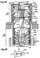
Fig. 9B is a bottom view of a portion of the
projection optical system shown in Fig. 9A;
Fig. 10 is a block view of the lenses that form
the projection optical system according to the fourth
embodiment of the present invention;
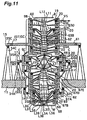
Fig. 11 is a cross-sectional view showing the
structure of the lens barrel of the projection optical
system according to the fourth embodiment of the
present invention;
Fig. 12 is a top view along line C - C of Fig.
11;
Fig. 13 is a block diagram of the lenses that
for the projection optical system according to the
fifth embodiment of the present invention;
Fig. 14 is a cross-sectional view showing the
structure of the lens barrel of the projection optical
system according to the fifth embodiment of the
present invention;
Fig. 15 is a perspective view of the divided
lens-barrel shown in Fig. 14;
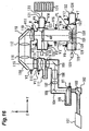
Fig. 16 is a diagram showing an example of the
projection exposure apparatus according to the
embodiments of the present invention; and
Fig. 17 is a diagram showing an example of a
manufacturing process of a semiconductor device
according to the embodiments of the present
invention.
DESCRIPTION OF THE PREFERRED EMBODIMENTS
[FIRST EMBODIMENT]
In the following, the first embodiment of the
present invention is described while referencing Fig,
2 to Fig. 4. This embodiment employs an F2 laser
(center wavelength of 157.6 nm) as an exposure light
(illumination light) and is applied to the invention
onto an upright cylindrical-shaped catadioptric
projection optical system with a reflective mirror
that has two apertures respectively formed near the
optical axes.
Fig. 2 is a lens block diagram of a projection
optical system according to this embodiment. In Fig.
2, an image of an object disposed in object plane 1
(first plane) is formed on image plane 4 (second
plane) by the projection optical system of this
embodiment with a predetermined projection
magnification β (lateral magnification).
Projection magnification β of this embodiment is
1/4x. During exposure, the pattern surface of the
reticle R, which is used as a mask, is disposed in
the object plane, and the surface of the wafer W (glass
plate, etc.), which is used as the to-be-exposed
substrate (photosensitive substrate), is disposed in
image plane 4.
The projection optical system of this
embodiment comprises a first imaging optical system
K1 for forming the pattern of a primary image
(intermediate image) 3 of the reticle pattern, and
a second imaging optical system K2 for forming a
secondary image (final image) of the reticle pattern
with reduction magnification onto the wafer based on
the light from the the primary image. The first
imaging optical system K1 comprises, in order from
the reticle side, a first lens group G1, which has
positive refractive power; aperture stop AS; and a
second lens group G2, which has positive refractive
power. A central shielding member 2, which shades the
light near the optical axis AX, is disposed near the
installation plane of aperture stop AS but in a
position that differs with the installation plane of
aperture stop AS in the direction of the optical axis.
The second imaging optical system K2 comprises,
in order from the reticle side, a primary mirror M1,
which has a superficial reflective surface with the
concave surface facing the wafer and has aperture
section 7 (light transmission section) in the center;
a lens L2; and a secondary mirror M2, which comprises
a reflective surface having aperture section 8 (light
transmission section) in the center. Furthermore,
the projection optical system of this embodiment has
eight aspherical surfaces, wherein the reference
marker ASPm is given to the m-th (m = 1, 2, ...)
aspherical surface in order from the reticle side.
The first lens group G1 comprises, in order from
the reticle side, a meniscus-shaped lens L11 with the
convex aspherical surface ASP1 thereof facing the
reticle side; a meniscus-shaped lens L12 with the
convex aspherical surface ASP2 thereof facing the
reticle side; and a meniscus-shaped lens L13 with the
concave aspherical surface ASP3 thereof facing the
wafer side. Furthermore, the second lens group G2
comprises, in order from the reticle side, a
biconcave-shaped lens L21 with the concave aspherical
surface ASP4 thereof facing the reticle side; a
biconvex-shaped lens L22 with the convex aspherical
surface ASP5 thereof facing the reticle side; a
meniscus-shaped lens L23 with the convex aspherical
surface ASP6 thereof facing the wafer side; and a
meniscus-shaped lens L24 with the concave aspherical
surface ASP7 thereof facing the wafer side. Moreover,
the lens L2 within the second imaging optical system
K2 is a meniscus-shaped lens with the concave
aspherical surface ASP8 thereof facing the reticle
side.
All of the optical elements (G1, G2, M1, M2, and
L2) that form the projection optical system of this
embodiment are disposed along a single optical axis.
The primary mirror M1 is disposed near the formation
location of the primary image 3, and the secondary
mirror M2 is disposed approaching the wafer.
In the projection optical system of Fig. 2, light
from the pattern of reticle R passes through the first
imaging optical system K1 and forms the primary image
(intermediate image) 3 of the reticle pattern. Light
from the the primary image 3 passes through aperture
section 7 at the center of the primary mirror M1 and
the lens L2 to be reflected by the secondary mirror
M2, and the light reflected by the secondary mirror
M2 passes through the lens L2 to be reflected by the
primary mirror M1. The light reflected by the primary
mirror M1 passes through the lens L2 and aperture
section 8 at the center of secondary mirror M2 to form
the secondary image of the reticle pattern on the
surface of wafer, with the reduction magnification.
Fluorite (CaF2 crystal) is used for all of the
refractive optical members (lens elements) that
construct the projection optical system in Fig. 2.
The oscillation center wavelength of the F2
laser light, which is used as the exposure light, is
157.6 nm, and the range of oscillation wavelength,
which is 157.6 nm ± approximately 10pm, is
narrow-banded, Throughout the range of wavelengths,
aberrations are favorably compensated at
predetermined, standardized conditions (e.g.
conditions where atmospheric pressure is 1 atm and
the accumulation of energy due to light passing
through the projection optical system is nearly zero).
The refractive index of CaF2 is 1.5600000 at the center
wavelength of 157.6 nm.
The shape of the aspherical surfaces employed
in the projection optical system of this embodiment
is given by the following expression; wherein, y is
the height perpendicular to the optical axis; Z
(amount of sag) is the distance in the direction of
the optical axis between a tangential plane at the
apex of the aspherical surface and a position at the
level of height y; r is the radius of curvature at
the apex of the aspherical surface; k is the conic
coefficient; and A to F are the respective n-th order
aspherical surface coefficients.
Z = (y2/r) / [ 1 + { 1- ( 1+κ ) · y2 / r2}1/2 ]
+ A · y4 + B · y6 + C · y8 + D · y10 + E · y12 + F · y14
The value of the respective elements of the
projection optical system in this embodiment is shown
in Table 1 below. In the Table 1, λ represents the
center wavelength of the exposure light; β
represents the projection magnification; NA
represents an image-side numerical aperture; and
represents an image circle diameter on the Wafer W.
Furthermore, Surface Number expresses the order of
the surfaces from the reticle side along the direction
in which light travels from the reticle plane, which
is the object plane, to the wafer plane, which is the
image plane; r is the radius of curvature of each
surface (mm; when aspheric, measured at the apex);
and d is the distance between each surface along the
optical axis (mm). Under the heading "optical
material," CaF2 indicates fluorite.
Furthermore, distance d between surfaces
changes its sign whenever reflection occurs. The
sign of distance d is negative throughout the optical
path from the secondary mirror M2 to the primary
mirror M1 and is positive throughout other paths.
Without regard to the direction of incidence of light,
facing the reticle, the radius of curvature r of
convex surfaces is considered positive and radius of
curvature r of concave surfaces is considered
negative. It is noted here that in all of the
following embodiments, the same reference markers are
used as in the first embodiment.
| (Principal Data) |
| λ = 157.6 nm±10pm |
| β = 0.2500 |
| NA= 0.75 |
| = 16.4mm |
| Distance from Reticle Plane to First Surface =201.4588mm |
| Surface Number | r | d | Optical Material |
| 1(ASP1) | 199.4802 | 23.6189 | CaF2 |
| 2 | 1933.2675 | 269.2901 |
| 3(ASP2) | 248.9463 | 38.4449 | CaF2 |
| 4 | 1002.9474 | 19.1120 |
| 5 | 109.3351 | 28.6306 | CaF2 |
| 6(ASP3) | 143.4010 | 21.0000 |
| 7(AS) | ∞ | 35.4787 |
| 8(ASP4) | -1979.6492 | 27.8589 | CaF2 |
| 9 | 215.9777 | 13.6424 |
| 10(ASP5) | 838.3987 | 20.3225 | CaF2 |
| 11 | -252.7298 | 143.5573 |
| 12 | -475.0282 | 25.5347 | CaF2 |
| 13(ASP6) | -98.4914 | 12.5880 |
| 14 | 174.9476 | 50.0000 | CaF2 |
| 15(ASP7) | 249.0939 | 370.2800 |
| 16(ASP8) | -965.4467 | 42.8265 | CaF2 |
| 17 | -8820.5445 | -42.8265 | CaF2 |
| 18(ASP8) | -965.4467 | -223.7172 |
| 19 | 346.8643 | 223.7172 |
| 20(ASP8) | -965.4467 | 42.8265 | CaF2 |
| 21 | -8820.5445 | 10.0000 |
| (Aspheric Data) |
| ASP1 | ASP2 | ASP3 |
| κ = 0.00000 | κ = 0.00000 | κ = 0.00000 |
| A = -9.61173 x 10⁻⁹ | A = -1.55615 x 10⁻⁷ | A = -1.49247 x 10⁻⁷ |
| B = -2.14569 x 10⁻¹³ | B = -4.68023 x 10⁻¹² | B = 2.48237 x 10⁻¹² |
| C = 7.59160 x 10⁻¹⁸ | C =3.66473 x 10⁻¹⁸ | C = 1.10343 x 10⁻¹⁵ |
| D = -5.90665 x 10⁻²² | D = 2.76851 x 10⁻²¹ | D = -6.65598 x 10⁻²⁰ |
| E = 0.0 | E = 4.46701 x 10⁻²⁵ | E = -2.1578 x 10⁻²⁴ |
| F = 0.0 | F = 0.0 | F = 0.0 |
| ASP4 | ASP5 | ASP6 |
| κ = 0.00000 | κ=0.00000 | κ= 0.00000 |
| A=-9.40388 x 10⁻⁸ | A = 1.88036 x 10⁻⁸ | A = 1.67077 x 10⁻⁷ |
| B = -4.01544 x 10⁻¹² | B = -1.59516 x 10⁻¹² | B = -2.42295 x 10⁻¹² |
| C = -6.89483 x 10⁻¹⁷ | C = -3.15148 x 10⁻¹⁶ | C = 1.58927 x 10⁻¹⁵ |
| D = 1.70469 x 10⁻²⁰ | D = -2.20945 x 10⁻²⁰ | D = -1.11815 x 10⁻¹⁹ |
| E = -6.15241 x 10⁻²⁴ | E = 0.0 | E = 1.37831 x 10⁻²³ |
| F = 0.0 | F = 0.0 | F = 0.0 |
| ASP7 | ASP8 |
| κ= 0.00000 | κ=17.06579 |
| A=-1.42562 x 10⁻⁷ | A = 7.65400 x 10⁻⁹ |
| B = 2.11000 x 10⁻¹¹ | B = -7.96595 x 10⁻¹⁵ |
| C = -3.82147 x 10⁻¹⁵ | C = -8.95740 x 10⁻¹⁹ |
| D = 2.44894 x 10⁻¹⁹ | D = 6.26276 x 10⁻²³ |
| E = 0.0 | E = -1.26805 x 10⁻²⁷ |
| F = 0.0 | F = 1.50073 x 10⁻³² |
As shown in the above, the catadioptric
projection optical system in Fig. 2, for F2 laser light
with the center wavelength having 157.6 nm, the image
side numerical aperture NA of 0.75 and the image
circle dimeter of 16.4 mm on the wafer are secured
using few lenses and without enlarging primary mirror
M1. When the projection optical system in Fig. 2 is
applied to a projection exposure apparatus, it is
possible to attain a high-resolution image of 0.1 µ
m or shorter. When the projection optical system in
Fig. 2 is applied to the step-and-scan type projection
exposure apparatus, if the exposure area upon the
wafer is set as a 15mmx6mm rectangular shape for
example, it is possible to transcribe the reticle
pattern into a 30mmx40mm area by performing stitching
exposure with two scanning exposure.
Next, the structure of the lens-barrel used when
the projection optical system of Fig. 2 is applied
to a projection exposure apparatus is described.
Fig. 3 is a cross-sectional view showing the main
components when mounting the projection optical
system of Fig.2 in the projection exposure apparatus.
In Fig. 3, the first imaging optical system K1
comprising lenses L11 to L24 is supported by barrel
5 which is an assembly of a plurality of divided
lens-barrels, and the second imaging optical system
K2 comprising the primary mirror M1, the lens L2, and
the secondary mirror M2, is held by second barrel 6,
which is an assembly of a plurality of divided
lens-barrels. Barrels 5 and 6 correspond to the
holding blocks in this invention. They are mounted
to the holding plate 11, which is the frame of the
projection exposure apparatus so as to be freely
detachable,
To begin with, the second barrel 6 is configured
by connecting divided lens-barrels 12 and 46 along
the optical axis, in order from the reticle side,
using bolts 23 in three places or more, and is mounted
on the U-shaped opening provided at the center of
plate 11 of the projection exposure apparatus, and
a flange section of the divided lens-barrel 12 located
at the top of barrel 6 is fixed to the plate 11 by
the bolts. In the upper divided lens-barrel 12, the
primary mirror M1 is supported so as to hang in three
locations by a V-shaped lens (mirror) mount mechanism
13 and a vertical drive element 14 which is extendable
along the optical axis; and within the lower divided
lens-barrel 46, the lens L2 and the secondary mirror
M2 are held by three vertical drive elements 15, one
lens mount 16, and one set of decentering drive
elements 17. For example, an electric micrometer,
piezoelectric elements, or a small electric motor may
be used for vertical drive elements 14 and 15. By
adjusting the amount of drive of the three locations
of vertical drive elements 14 and 15, it is possible
to adjust the position of the optical elements (the
primary mirror M1, the lens L2, and the secondary
mirror M2) along the optical axis AX, as well as the
respective tilt angles about the two axes orthogonal
thereto.
On the other hand, a set of decentering drive
elements 17 comprises two drive elements, such as an
electric micrometer, piezoelectric element, or small
motor, which moves the respective optical elements,
which are the objects to be held, along the two
orthogonally-intersecting axes of the horizontal
plane perpendicular to the optical axis AX; and an
applying section, such as a coil-shaped spring, which
presses the optical elements against these drive
units. By controlling the amount of movement of the
two drive units in the decentering drive element 17,
it is possible to adjust the amount of decentering
along the two axes that orthogonally intersect the
optical elements. It is noted here that the
cross-sectional view of Fig. 3 (in the same manner
as for the respective cross-sectional views of the
other embodiments below) shows the section along the
plane which has every 120 degree angle centered at
the optical axis AX in the connection with the
vertical drive elements (e.g. 14 and 15) and bolts
23; and in regards to decentering drive element 17,
shows normal frontal view.
The first barrel 5 comprises, in order from the
reticle side, an active divided lens-barrel 22A,
which holds the lens L11; the lens-barrel 24, which
acts as a spacer; an active divided lens-barrel 22B,
which holds the lens L12; the lens L13; an active
divided lens-barrel 25A, which holds the aperture
stop AS and the shielding member 2; an active divided
lens-barrel 25B, which holds the lens L21; an active
divided lens-barrel 22C, which holds the lens L22;
an active divided lens-barrel 22D, which holds the
lens L23; and an active divided lens-barrel 22E, which
holds the lens L24, all of which being connected along
the optical axis by bolts 23 in three or more locations,
respectively. The flange section of the lowermost
active divided lens-barrel 22E is fixed to the top
of the second barrel 6.
Each of the five active divided lens-barrels
from 22A to 22E are assembled so that a lens mount
21 is arranged in an outer barrel 18 through
freely-rotating flanges 19 and vertical drive
eLements 20 at three places. The optical element (the
lens L11 to the lens L24) is held in the lens mount
21. The assembly of vertical drive element 20 is in
the same manner of vertical drive elements 14 and 15;
wherein each of the five active divided lens-barrels
22A to 22E are able to adjust the position of internal
lenses L11 to L24 along the optical axis AX and the
tilt angle about the two axes orthogonal thereto.
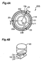
Fig. 4A is a cross-sectional view along line A-A
in Fig. 3. In Fig. 4A, vertical drive elements 20 of
Fig. 3 are disposed at positions 20A to 20C at
equiangular intervals about the optical axis AX as
the center. Bolts 23, which connect the outer barrel
18 of the active divided lens-barrel 22A and a spacing
lens-barrel 24, are arranged in notch 18a, which
provided at three places on the circumference of the
outer barrel 18. In comparison with the method which
connects the two barrels by binding flange parts from
the outer surface of each barrel, for example, it is
possible to make the divided lens-barrel 22A from
fewer parts and reduce its manufacturing costs.
There are 0-rings arranged respectively at a groove
between lens-barrels (not shown in the Figure) for
maintaining the high purity of the purge gas inside
the lens-barrels. Bolts 23 can be disposed at three
places or more, or for example, as many as twelve
places, for increasing the degree of seal of the
adjoining lens-barrels. The cross section along
line B-B in Fig. 4A corresponds to the cross section
of the first barrel 5 in Fig. 3.
Fig. 4B is an enlarged perspective view showing
the flange 19 and the vertical drive element 20 in
Fig. 3. In Fig. 4, the flange comprises a holder 32;
a lobe 31, which is connected to the holder 32 so that
it can freely rotate; and a pin 33, which joins the
holder 32 and the lobe 31. The end of vertical drive
element 20 is connected to the lobe 31. Although the
flange 19 is able to rotate around one axis in this
arrangement, it is possible to arrange the flange with
rotation around two axes.
Returning to Fig. 3, the drive amount of the
vertical drive elements 20 of the active divided lens
barrels 22A to 22E, the drive amount of vertical drive
elements 14 in the second barrel 6, and the drive
amounts of decentering drive elements17 are
controlled by an imaging characteristics control
system 27. Each drive element 20, 14, and 17 has a
sensor (rotary encoder, electrostatic capacity-type
or optical gap-type sensor) for detecting their
respective amounts of drive, so that the imaging
characteristics control system 27 controls the drive
amount of the respective drive element 20, 14, and
17, while receiving outputs from respective sensors .
The operation of imaging characteristics
control system 27 is controlled by a main controlling
system 26, which performs supervisory control over
the components of the projection exposure apparatus.
The main controlling system 26 receives data with a
predetermined sampling rate from an environment
sensor 28, which comprises, for example, a barometric
sensor that measures the atmospheric pressure around
the projection exposure apparatus in this embodiment;
a thermometer, which measures the temperature about
the circumference; and a hygrometer etc., Moreover,
the projection exposure apparatus includes an
exposure control system 29, which indirectly obtains
the accumulated energy of the exposure light
(illuminating light) passing through the projection
optical system by monitoring the illuminance (pulse
energy) of a split light from the exposure light in
the illumination optical system. When the
atmospheric pressure about the circumference and
accumulated energy changes, the characteristics or
the imaging optical system such as, best focus point,
projection magnification, and aberrations
(distortion, astigmatism, field curvature, spherical
aberration, and coma etc.) accordingly change;
therefore, the relationship between the change in
atmospheric pressure, accumulation of energy and so
on, and the change in the characteristics such as the
magnification of the projection is pre-stored as a
table in the memory of the main control system 26.
When the measured values of, for example, atmospheric
pressure changes, or when the accumulation of energy
accordingly increases, the main controlling system
26 drives the five lenses L11 to L24 to counterbalance
the corresponding change in the characteristics of
imaging through the imaging characteristics control
system 27 and vertical drive elements 20. It is noted
here that it is possible to handle the change of the
best focus point by controlling the focus point on
the wafer W. It is also possible to compensate
further by driving the primary mirror M1 and the lens
L2 (the secondary mirror M2) through vertical drive
elements 14, 15 and decentering drive element 17, if
necessary.
Since the exposure light (illuminating light)
is an F2 laser (a center wavelength is 157.6 nm), a
high-purity purge gas, which allows greater
transmissivity of light in the vacuum ultraviolet
(VUV) region is supplied in an optical path of the
exposure light. Nitrogen gas, or a suitable noble gas
(such as helium, neon, argon, krypton, xenon, or
radon), which are chemically inert gasses, can be used
as the purge gas. Although nitrogen gas provides
comparatively high transmissivity and low cost with
light having wavelengths of approximately 150 nm or
longer, absorption of the light is increased for light
having wavelengths of less than approximately 150 nm.
Helium gas is expensive, but it provides
comparatively high transmissivity for light having
wavelengths down to approximately 100 nm. Moreover,
helium gas has advantages of high thermal
conductivity (three times higher than neon, and six
times higher than Nitrogen), excellent thermal
stability, and relatively low fluctuation in the
refractive index corresponding to the change of
atmospheric pressure (1/2 that of neon, and 1/8 that
of nitrogen gas). For these reasons, helium gas is
used as the purge gas in this embodiment.
Therefore, in Fig. 3, a supply pipe with an
attached valve V5 is connected to the lens-barrel 24
as a spacer in first barrel 5 from the supply apparatus
(not shown in the Figure), and temperature-controlled
high-purity purge gas is supplied into the projection
optical system from the supply apparatus. The
exhaust pipe with an attached valve V15, which leads
to the supply apparatus, is connected to the divided
lens-barrel of the second barrel 6. The purge gas
that has flowed through the projection optical system
is returned to the supply apparatus through the
exhaust pipe. In the supply apparatus, the purge gas
is supplemented for the gas lost due to leakage, and
after removing the impurities in the returned gas,
is supplied again into the projection optical system
through the supply pipe.
The purge gas is able to circulate through the
space beneath the supply pipe between each of the
three vertical drive elements 20 that drive lenses
L12 to L24, respectively, and also through the many
openings formed at almost equiangular intervals on
the lens mount 21 which holds the lens inside active
divided lens-barrels 22B to 22E and on lens mount of
divided lens-barrels 25A and 25B. The purge gas is
able to circulate without stagnation in the first
barrel 5 toward the second barrel 6. As an example,
a sealing member 9 which is accordion-shaped and
tightly-sealed is disposed between the lens mount 21,
which holding the lens 11, at the top of the first
barrel 5 and the outer barrel 18 to prevent the purge
gas from leaking.
The purge gas that flows into the second barrel
6 reaches the space over the lens L2 through the spaces
in the lens mount mechanism 13, the space outer side
of the primary mirror M1, and the aperture at the
center of the primary mirror M1 and it is released
through the exhaust pipe with an attached valve V15.
Since the high-purity purge gas is supplied into a
gastight chamber where the wafer W is received (or
gas-tight chamber where the wafer-stage system is
received), a certain volume of purge gas can leak from
the margin of the lens L2 at the bottom of the second
barrel 6 to the wafer W side. However, in the case
where the prevention of purge gas leakage from the
margin of the lens L2 and the wafer W side is desired,
it is preferable that sealing material be placed into
the space between the margin of the lens L2 and the
divided lens-barrel 46.
As mentioned above, with the projection optical
system of this embodiment, the first imaging optical
system K1 and the second imaging optical system K2
are disposed such that the primary image 3
(intermediate image) is sandwiched between them, and
the outside diameter of the first imaging optical
system K1 and the second imaging optical system K2
differ considerably. By having the first imaging
optical system K1 supported by the first barrel 5,
the second imaging optical system K2 supported by
second barrel 6, and the primary image 3 sandwiched
there between, all of the optical elements that
construct the projection optical system can easily
be mechanically supported.
When considering each optical element in the
catadioptric projection optical system, the amount
of the aberration due to the dislocation of the
reflective member is considerably larger than that
for the refractive member. Since the refractive
index of the reflective member is 2.0 with the
refractive member having a refractive index 0.5, the
amount of change in the refractive index of the
reflective member due to dislocation is 4 times that
of the refractive member because of Snell's law. On
the other hand, even if the assembly of each of the
barrels 5 and 6 is completed, due to various causes
their positional relationship to each other can be
considered to change ever so slightly; however, the
relative positioning of the optical elements within
each of the barrels 5 and 6 can expected to be preserved
because they are supported connected to each other.
As shown above, the configuration having all
of the reflective members (M1 and M2) disposed within
one barrel, barrel 6, as in this embodiment is
advantageous in that, even when that the barrel 6 has
moved, if it is considered that the barrel 6, which
includes those reflective members, is the standard
and that the other barrel, barrel 5 has moved, it
substantially means that only the refractive members
have moved, so that the amount of aberrations that
develop is low compared to cases where they are
separately disposed in a plurality of barrels.
It is noted here that, generally, in order to
utilize the ability of the surface of the reflective
mirror enough, sufficient clear aperture diameter is
required, and that in this regard, production is
easier if the material diameter of the refractive
members is small. In order to handle this, it is
effective to produce an intermediate image, make the
light beam smaller, and set the lens group only from
the refractor and the other lens group, which mainly
comprises the reflective mirror as an optical element .
When thought of in this manner, in most the
catadioptric projection optical systems that form an
intermediate image, not limited to just the
projection optical system of this embodiment, if the
Lens group that forms the intermediate image is formed
as a unit in the barrel, the outer diameters of the
optical elements within each barrel are relatively
aligned, so that along with simplifying mechanical
support, since the reflective member and the
refractive member are separated before and after the
intermediate image, the amount of aberrations that
develop is reduced.
Next, the adjustment ability of the projection
optical system in Fig. 3 is described. The projection
optical system in this embodiment includes eight
aspherical surfaces, and during production, there
have a fear that they may become shifted to the degree
of several µm. Even though these lenses are
assembled in relation to the optical axis as the
center, there is the possibility of high-order
decentered aberration occurring due to the shifting
of aspherical surfaces relative to the optical axis.
To handle this problem, it is desirable that the
components have decentered aberration adjusting
ability of the same number of or more, corresponding
to the aspherical surface.
As mentioned above, when reflective members
shift from their designed positions, large
aberrations are generated. For this reason, in cases
where the system has two or more reflective members,
one reflective member must be adjusted relative to
the other reflective member. Consequently, in this
embodiment, and as shown by divided lens-barrels 12
and 46, a single holding block is made having only
a single reflective member in.
Next, a procedure of the manufacturing
process is described. It is generally considered
that there are large aberrations generated from the
reflective members in the projection optical system.
However, even if results of measuring aberrations in
the projection optical system first show the
development of a large aberration, there are many
cases where the location of aberration development
cannot be determined.
As a countermeasure to such cases, if there is
another projection optical system, which is already
completed, exchanging of only one barrel between
completed system and manufacturing system can be
considered. In this embodiment, if the second barrel
6, which supports holding the reflective members, is
replaced with only the second barrel of a completed
system, while observing the image of that projection
optical system, divided lens-barrels 12 and 46 within
second barrel 6 can be adjusted through translation
or by being tilted. In this case, since only the
second barrel 6 of the completed system is replaced,
if there is any kind of aberration, then all of the
aberrations would come from the second barrel. If the
second barrel 6 is adjusted while observing the image,
the barrel 6 can be adjusted to a state that is near
the ideal position consequently. The adjusted second
barrel 6 is reset and readjusted with the first barrel
5. Once this adjustment is completed, since only the
first barrel 5 needs to be adjusted, the adjustment
of the whole projection optical system can be
completed in a short time.
If adjustment is performed in this manner, the image
approaches the designed values. However, if the
adjustment between each divided lens-barrel (holding
block) is performed with the barrel being removed from
the holding plate 11, since it is impossible to make
adjustment while observing the real time image,
there is the possibility that the aberrations will
remain in the adjustment tolerances of each of the
barrels. To remove the remaining aberrations, and to
correct the aberrations due to atmospheric pressure,
the five lenses L11, L12, and L22 to L24 are composed
in a manner such that they can be performed vertical
movement along the optical axis and tilt movement by
controlling from outside . The reason why there are
five controllable optical elements prepared is so
that there are enough to compensate third order
aberrations along the optical axis and decentered
aberrations. This adjustment mechanism is
completely comprised within the first barrel 5. This
is because the second barrel 6 comprises only
reflective members (the lens L2 is considered a rear
surface reflective mirror), and because the
reflective members are not fit for delicate
adjustment because they generate large aberrations.
By using this adjustment mechanism it is possible to
remove all residual aberration, and along with being
possible to manufacture a projection optical system
having approximately the same performance as designed,
it is also possible to maintain an ideal state of
imaging characteristics.
Furthermore, the primary mirror M1 is supported
by the lens mount mechanism 13. By constructing this
as a frame, the support members of the reflective
mirrors do not divide the atmosphere within the
lens-barrel. As a result of this, when the atmosphere
within the lens-barrels is replaced with an inert gas
such as helium, it becomes possible to perform
expedited replacement without causing residual
(retentive) gas to develop. Moreover, by using a
frame construction, the reflective mirror support
members can be made lighter.
[SECOND EMBODIMENT]
Next, a projection optical system according to
the second embodiment of the present invention is
described while referencing Fig. 1 and Figs. 5 to 7.
This embodiment employs an F2 laser (central
wavelength of 157.6 nm) as the exposure light and is
used in the present invention onto an upright
cylindrical catadioptric projection optical system
including two reflective mirrors, the respective
apertures thereof formed along each of the two optical
axes. In Figs. 5 to 7, the portions corresponding to
those of Figs. 2 and 3, are assigned the same or similar
reference mark and their detailed description is
omitted.
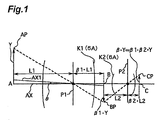
Fig. 1 is a schematic view of the projection
optical system of this second embodiment. In Fig. 1,
the projection optical system of this embodiment
comprises a first imaging optical system K1 and a
second imaging optical system K2; wherein a light from
object point AP, which is located at height Y of a
position A on an optical axis AX, passes through the
first imaging optical system K1 to form a primary
image BP (intermediate image) at height β1 · Y (β1
is a real number other than zero) of a position B,
and light from first image BP passes through the
second imaging optical system K2 to form a image point
CP at height β1 · β2 · Y (β2 is a real number other
than zero) of a position C. At this time, when the
projection magnification of the entire projection
optical system is given as β, then the expression β
= β1·β2 may be concluded. Furthermore, the second
imaging optical system K2 includes the reflective
members.
In Fig. 1, imaging optical systems K1 and K2 are
mechanically integrally held, independent of each
other, by a first barrel 5A and a second barrel 6A,
respectively. In this case, when deciding the most
appropriate position for barrels 5A and 6A to be held,
in order to maintain high performance image forming,
it is preferable that image shift does not occur even
when barrels 5A and 6A are tilted. Such a position
is, for example, position P1 where a segment between
a positions A and B is internally divided by a ratio
of 1 ; β1 when first imaging optical system operates
at positions A and B with the magnification of -
β1 (β1 > 0). This is because, in the case of the
interval between the position A and the point P1 in
Fig. 1 is given as L1, when the first imaging optical
system Kl is tilted by only an angle , since the point
that is originally located at the position A has a
height of L1 · relative to the optical axis of the
tilted optical system, a point at which imaged this
becomes a point having a height of - β1 · L1 ·
relative to the optical axis of the tilted optical
system; however, this is the point at position B upon
the original optical axis. In the same manner, in
regard to the point that had the originally
predetermined image height as well, even if the system
is tilted, image shift does not occur except
distortion. Consequently, when the barrel 5A is
supported at a position on a horizontal plane that
is orthogonal to the optical axis AX, which point P1
passes through, or at a position near said horizontal
plane, even if barrel 5A is tilted, image shift does
not occur. In the same manner, when the magnification
of the second imaging optical system K2, which
performs imaging relative to the position B to the
position C, is β2, the barrel 6A should be supported
at a position on the horizontal plane that is
orthogonal to the optical axis AX at the position P2,
which internally divides the interval between
position B and the position C in a ratio of 1 : β
2, or at a position near said horizontal plane.
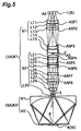
Fig. 5 is a lens block diagram of the projection
optical system according the second embodiment. In
Fig. 5, the exposure light (illuminating light) IL,
which passes through the pattern of the reticle R that
is disposed in the object plane 1 passes through the
first imaging optical system K1 to form the primary
image 3 (intermediate image) ; and the light from the
primary image 3 passes through the second imaging
optical system K2 to form a reduced secondary image
(final image) of the reticle pattern on the surface
of the wafer W, which is disposed in the image plane
4.
The first imaging optical system K1 comprises,
in order from the reticle side, a first lens group
G1, which has a positive refractive power; an aperture
stop AS; a second lens group G2, which has a positive
refractive power; and a lens 30, which is concave on
both sides and has a negative refractive power. A
central shielding member2 which shades the light
around the optical axis AX, is set close to the
facilitation plane of the aperture stop AS, but in
a position that differs with the facilitation plane
of the aperture stop AS along the optical axis.
The second imaging optical system K2 comprises,
in order from the reticle side, a primary reflective
mirror M1, which has a superficial reflective surface,
the concave surface thereof facing the wafer side,
and includes an aperture (a light transmission
section) 7; and a secondary reflective mirror M2,
which has a superficial reflective surface, the
concave surface thereof facing the wafer side, and
includes an aperture (a light transmission section)
8. Furthermore, the projection optical system of
this embodiment includes eight aspherical surfaces
ASP1 to ASP8.
The first lens group G1 comprises, in order from
the reticle side, meniscus-shaped lens L11, the
convex aspherical surface ASP1 thereof facing the
wafer side; a meniscus-shaped lens L12 with the
concave surface facing the reticle side; a
meniscus-shaped lens L13 with the convex aspherical
surface ASP2 facing the wafer side; a meniscus-shaped
lens L14 with the concave aspherical surface ASP3
facing the reticle side; and a bi-convex-shaped lens
L15. The second lens group G2 comprises, in order
from the reticle side, a bi-convex-shaped lens L21
with the convex aspherical surface ASP4 facing the
reticle side; a meniscus-shaped lens L22 with a
concave surface thereof facing the reticle side; a
meniscus-shaped lens L23 with the convex aspherical
surface ASPS facing the reticle side; a
biconvex-shaped lens L24 with the convex aspherical
surface ASP6 facing the reticle side; a
meniscus-shaped lens L25 with the concave aspherical
surface ASP7 facing the wafer side; a biconvex-shaped
lens L26; a biconvex-shaped lens L27 with the convex
aspherical surface ASP8 facing the reticle side; and
a biconvex-shaped lens L28.
In this manner, with the projection optical
system in Fig. 5, light from the pattern of the reticle
R passes through the first imaging optical system K1
and forms the primary image 3 (intermediate image)
of the reticle pattern. The light from the primary
image 3 travels through aperture 7 at the center of
the primary reflective mirror M1 to be reflected by
the surface of a secondary reflective mirror M2; and
the light reflected by the surface of a secondary
reflective mirror M2 is reflected by the surface of
the primary reflective mirror M1. The light
reflected by the primary reflective mirror M1 travels
through the aperture 8 at the center of a secondary
reflective mirror M2 to form the reduced the secondary
image of the reticle pattern on the surface of the
wafer W.
Fluoride (CaF2 crystal) is used for all of the
refractive optical members (lens elements) that
constitute the projection optical system of Fig. 5.
Furthermore, the oscillation center wavelength
of the F2 laser light, which is used as the exposure
light, is 157.624 nm; the range of oscillation
wavelength, 157.624 nm ± approximately 1 pm, is
narrow-banded; and the refractive index of CaF2 is
1.559238, at the center wavelength of 157.624 nm.
Moreover, the respective shapes of the aspherical
surfaces used in the projection optical system of this
embodiment is given by the expression (1).
The value of each factor of the projection
optical system according to this embodiment shown in
Table 3 corresponds to that shown in Table 1.
| (Principal Data) |
| λ= 157.624 nm±1pm |
| β=0.2500 |
| NA= 0.75 |
| = 16.4mm |
| Distance from Reticle to First Surface =97.4647mm |
| Surface Number | r | D | Optical Material |
| 1 | -133.8316 | 35.0000 | CaF2 |
| 2(ASP1) | -116.4714 | 1.0000 |
| 3 | -554.1774 | 20.5256 | CaF2 |
| 4 | -213.7250 | 25.1023 |
| 5 | -261.9616 | 20.0289 | CaF2 |
| 6(ASP2) | -168.6391 | 20.3246 |
| 7(ASP3) | -96.4098 | 25.0000 | CaF2 |
| 8 | -163.9518 | 5.8731 |
| 9 | 782.1145 | 40.0000 | CaF2 |
| 10 | -194.0414 | 1.1373 |
| 11(AS) | ∞ | 20.6498 |
| 12(ASP4) | 104.9826 | 24.2585 | CaF2 |
| 13 | -1294.5816 | 10.7993 |
| 14 | -152.5389 | 20.0000 | CaF2 |
| 15 | -858.7147 | 38.4039 |
| 16(ASP5) | 798.2520 | 20.1464 | CaF2 |
| 17 | 198.7615 | 4.1296 |
| 18(ASP6) | 261.7539 | 29.0815 | CaF2 |
| 19 | -501.0834 | 63,3677 |
| 20 | 3299.4456 | 30.0000 | CaF2 |
| 21(ASP7) | 360.6533 | 36.6971 |
| 22 | 1401.8392 | 34.4568 | CaF2 |
| 23 | -170.8148 | 5.9831 |
| 24(ASP8) | 266.5085 | 24.4029 | CaF2 |
| 25 | -370.3218 | 38.2791 |
| 26 | 255.6101 | 39.9997 | CaF2 |
| 27 | -1343.1549 | 49.5384 |
| 28 | -142.9084 | 21.2041 | CaF2 |
| 29 | 112.3957 | 14.2675 |
| 30 | 427.9297 | 284.4437 | (Virtual Plane) |
| 31(M2) | -3734.1426 | -284.4437 |
| 32(M1) | 427.9297 | 284.4437 |
| 33 | -3734.1426 | 13.3911 | (Virtual Plane) |
| (Aspheric Data) |
| ASP1 | ASP2 | ASP3 |
| κ = 0.0000 | κ = 0.0000 | κ = 0.0000 |
| A = 7.4338 x 10⁻⁸ | A = -3.1895 x 10⁻⁸ | A = -1.8862 x 10⁻⁷ |
| B = 1.4821 x 10⁻¹² | B = 1.5252 x 10⁻¹² | B = -2.5593 x 10⁻¹² |
| C = 2.8340 x 10⁻¹⁶ | C = -1.5642 x 10⁻¹⁶ | C = -1.2889 x 10⁻¹⁵ |
| D = 1.0465 x 10⁻²¹ | D = 1.0493 x 10⁻²⁰ | D = 1.3308 x 10⁻¹⁹ |
| E = 2.3982 x 10⁻²⁴ | E = -7.2790 x 10⁻²⁵ | E = 2.2662 x 10⁻²³ |
| F = 0.0 | F = 0.0 | F = 0.0 |
| ASP4 | ASPS | ASP6 |
| κ = 0.0000 | κ = 0.0000 | κ = 0.0000 |
| A = -1.7279 x 10⁻⁷ | A = -7.8055 x 10⁻⁸ | A = 1.4844 x 10⁻⁸ |
| B = -2.6931 x 10⁻¹¹ | B = 2.4611 x 10⁻¹¹ | B = -1.7927 x 10⁻¹¹ |
| C = -2.7058 x 10⁻¹⁵ | C = -3.3373 x 10⁻¹⁵ | C = 3.0001 x 10⁻¹⁵ |
| D = -2.7673 x 10⁻¹⁹ | D = -5.8685 x 10⁻¹⁹ | D = 3.4128 x 10⁻¹⁹ |
| E = -8.2067 x 10⁻²³ | E = 6.5684 x 10⁻²³ | E = -7.3746 x 10⁻²³ |
| F = 0.0 | F = 0.0 | F = 0.0 |
| ASP7 | ASP8 |
| κ = 0.0000 | κ = 0.0000 |
| A = 9.0882 x 10⁻⁸ A = | 1.3982 x 10⁻⁸ |
| B = -1.6366 x 10⁻¹² | B = 2.9315 x 10⁻¹³ |
| C = 1.4369 x 10⁻¹⁶ | C = 8.0049 x 10⁻¹⁷ |
| D = -9.1173 x 10⁻²⁰ | D = -2.5823 x 10⁻²⁰ |
| E = 4.3321 x 10⁻²⁴ | E = 1.2241 x 10⁻²⁴ |
| F = 0.0 | F = 0.0 |
As shown above, with the catadioptric
projection optical system in Fig. 5, for F2 laser, the
image side numerical aperture NA of 0.75 and the image
circle diameter of 16.4 mm on the wafer are secured
using few lenses and without enlarging primary mirror
M1.
Next, the structure of the lens-barrel used when
the projection optical system of Fig. 5 is applied
to a projection exposure apparatus is described.
Fig. 6 is a cross-sectional view showing the main
components when the projection optical system of Fig.
5 is mounted in a projection exposure apparatus. In
Fig. 6, the first imaging optical system K1 comprising
lenses L11 to L28, and L30 is supported by the first
barrel 5A (a lens-barrel unit), which is an assembly
of a plurality of divided lens-barrels (holding
blocks). The second imaging optical system K2, which
comprises the primary reflective mirror M1, the lens
L2, and the secondary reflective mirror M2, is
supported by the second barrel 6A (lens-barrel unit),
which is an assembly of a plurality of divided
lens-barrels (holding blocks). The barrel 5A is
attached to the top of a supporting plate 11 of the
projection exposure apparatus so as to be freely
detachable. The barrel 6 is attached to the bottom
of holding plate 11 so as to be freely detachable and
to be suspended.
To begin with, the second barrel 6A comprises
two divided lens-barrels 37 and 36 connected through
vertical drive elements 15 at three locations or more.
A flange section of the divided lens-barrel 36 is held
by a ring-shaped holding member 35B through
decentering drive element 17. The holding member 35B
is held so as to be suspended by three V-shaped holding
members 34B, which are fixed to the base of the
perimeter of an aperture formed on the holding plate
11, a joint 19 and a vertical drive element 14. In
the divided lens-barrel 37, a primary reflective
mirror M1 is held by the decentering drive element
17. In the divided lens-barrel 36, a lens mount 38
is held by a joint 19 and the vertical drive element
15 in three places. The secondary reflective mirror
M2 is held by lens mount 38. Based on this
configuration, it is possible to control (hereafter
referred to as "control of aberrations with five
degrees of freedom") the position of the optical axis
of the second barrel 6A as a whole unit relative to
the plate 11, the tilt angle around two
orthogonally-intersecting axes, and the shift of the
two directions comprising the plane perpendicular to
the optical axis AX. It is possible to perform
control of aberration with five degrees of freedom
for the primary reflective mirror M1 relative to the
second barrel 6A. It is also possible to control
(hereafter referred to as "control of aberrations
with three degrees of freedom") the position along
the optical axis and the tilt angle about the two axes
for secondary reflective mirror M2 relative to the
second barrel 6A.
When the magnification of the second imaging
optical system K2 (the primary reflective mirror M1
and the secondary reflective mirror M2) corresponding
from the primary image 3 to the surface of the wafer
W is-β2, the plane through the center of the joint
19 (the bottom of the holding member 34B), and
perpendicular to the optical axis AX, also passes
through the position which internal divides the
segment between the surface of the pattern of the
reticle R and the primary image 3 along the optical
axis AX in the ratio of 1 ; β1 and nearly contacts
the plane perpendicular to the optical axis AX. Here,
the joint 19 works as a supporting plane of the barrel
6A, and β1 =-0.49 in this embodiment. Because of
this arrangement, there is no lateral shift of the
projected image even when the second barrel 6A rotates
about the holding plane.
The first barrel 5A comprises, in order from the
reticle side, an active divided lens-barrel 44, a
divided lens-barrel 45A, active divided lens-barrels
44B and 44C, divided lens-barrels 39 and 45B, and
active divided lens-barrels 44D and 44E, which are
connected along the optical axis using bolts (not
shown in the Figure) at three locations or more,
respectively; and the flange section of the divided
lens-barrel 39 arranged in the middle section is
supported through decentering drive element 17 by a
ring-shaped holding member 35A. The holding member
35A is held by three inverted-V-shaped holding
members 34A fixed to the top of the circumference of
the aperture formed on the holding plate 11, a joint
19 and a vertical drive element 14, Through this
configuration, it is possible to perform control of
the position of the entire first barrel 5A with five
degrees of freedom relative to the holding plate 11.
The five active divided lens-barrels 44A to 44E
respectively hold a lens mount 41, a vertical drive
element 20, and a spacer 42 in outer barrel 40 (the
order of these is flexible). Within the spacer 42,
the lens mount 43 is held via decentering drive
element 17. Lens mounts 41 and 43 each hold lenses.
The five active divided lens-barrels 44A to 44E hold
lenses L11, L14, L22, L26, L30, respectively, with
the condition of being able to control displacement
within five degrees of freedom. Active divided
lens-barrels 44A, 44B, and 44D hold lenses L12, L15,
and L27, respectively, with at rest conditions.
Active divided lens-barrels 44C and 44E hold lenses
L21 and L28, and lenses L22 and L30, respectively,
so as to control displacement within three degrees
of freedom. Active divided lens-barrels 45A and 45B
hold lenses L13 and L25, respectively, via the lens
mount 41. The active divided lens-barrels 39 holds
lenses L23 and L24 through the two lens mounts 41.
In Fig. 6, the operation of all vertical drive
element 14, 15, and 20 and decentering drive element
17 are controlled by the imaging characteristics
control system, which is equivalent to the imaging
characteristics control system 27 in Fig. 3. As a
result, it is easy to determine the relative positions.
of the primary reflective mirror M1 and the secondary
reflective mirror M2 during assembly and adjustment
of the projection optical system in this embodiment.
It is also possible to reduce the amount of residual
aberrations after constructing the barrel 5A.
Further, it is possible to perform adjustments during
the exposure process, if necessary,
Furthermore, if the projection magnification of
the first imaging optical system K1 (lenses L11 to
L30) is given as - β1, for the primary image 3 from
the pattern surface of the reticle R, then the plane,
which is the holding plane of the first barrel 5A
passing through the center of the joint 19 (the top
of the holding member 34A), orthogonal to the optical
axis AX, also passes through the position that
internally divides the distance between the primary
image 3 and the surface of the wafer W along the optical
axis AX in the ratio of 1 : β1 to nearly contact the
plane orthogonal to the optical axis AX. In this
embodiment, β1 = -0.51 and accordingly there is no
lateral shift even when the first barrel 5A rotates
about the holding plane.
It is noted here that even though the lens L30
is located 10 mm below the primary image 3
(intermediate image), it belongs to first barrel 5A
(the first imaging optical system K1) when
considering mechanical balance. In this case, the
intermediate image is a virtual image; however, this
fact does not affect the above description.
Furthermore, since the projection optical
system in this embodiment comprises eight aspherical
surfaces, there are block structures (divided
lens-barrels 44A, 45B, 44B, ... 37, and 36) at ten places
more than the number of aspherical surfaces.
Accordingly, the relationship among the aspherical
surfaces can be set the predetermined value with high
accuracy to the design value.
Fig. 7 is the top view of Fig. 6. In Fig. 7,
vertical drive elements 20 in Fig. 6 are disposed at
three predetermined locations 20A to 20C at
equiangular intervals about the optical axis AX.
Furthermore, decentering drive elements 17 in Fig.
6 comprise drive elements 17A and 17C, which move the
lens mount 43 in two orthogonally-intersecting
directions; and holding elements 17B and 17D, which
press the lens mount 43 against these drive elements.
Furthermore, there are eight openings 43a formed in
the lens mount 43 to allow the purge gas to flow
smoothly.
Returning to Fig. 6, each lens mount 41 also has
a plurality of openings to allow the purge gas to flow.
Nitrogen gas is used as the purge gas in this
embodiment. The high-purity purge gas supplied into
the gastight chamber (the reticle stage chamber)
where the respective reticles are stored, is into the
second barrel 6A through openings 43 of the lens mount
41 in the first barrel 5A of the projection optical
system. The purge gas led into the barrel 6A is led
into the gastight chamber (wafer stage chamber)
through the openings (not shown in the Figure)
provided in the lens mount 38, and the aperture at
the center of the secondary reflective mirror M2.
Since there is a plurality of openings formed on each
lens mount 41 and 43, when the air within the
projection optical system is replaced with a purge
gas, it becomes possible to perform quickly
replacement without causing residual (retentive) gas
to develop. Moreover, by using a frame construction,
the reflective mirror support members can be made
lighter,
To improve the gas tightness of the first barrel
5A, there are O rings (not shown in the Figure)
inserted between the respective divided lens-barrels
44A, 45A, 44B, and so on. In order to seal the space
between the first barrel 5A and the second barrel 6A,
for example, an extendable accordion-shaped
sheathing member 9A is prepared, and in order to
sheath vertical drive elements 15 between divided
lens-barrels 36, and 37, an extendable sheathing
member (not shown in the Figure) is provided so that
there is no lateral intermixing from the outside of
the projection optical system. Through this
configuration, the high-purity purge gas within the
projection optical system can be maintained.
[THIRD EMBODIMENT]
The third embodiment of the projection optical
system according to the present invention is
described using Figs. 8 and 9. In the third
embodiment, the present invention is applied to the
off-axis catadioptric type (a light passes through
the outside of the predetermined reflecting mirror)
projection optical system, which uses the ArF excimer
laser (central wavelength: 193.3 nm) is used as the
exposure light. For the parts in Figs. 8 and 9
corresponding to the parts in Figs. 2 through 6, the
same or similar reference numerals and detailed
descriptions are omitted.
Fig. 8 is a block diagram of the lens of the
catadioptric type projection optical system in this
embodiment. In Fig. 8, the projection optical system
of this embodiment comprises: a catadioptric type
first imaging optical system G1, which forms
intermediate image I1 of reticle R pattern on the
object plane (the first plane); and dioptric type
second imaging optical system G2, which forms the
final image of the reticle pattern on the wafer W
surface on image plane 4 (second plane) with
telecentric light beam, based on the light provided
from intermediate image Il. First and second imaging
optical systems G1 and G2 are held by first and second
barrels 5B and 6B, respectively.
The first imaging optical system G1 comprises
a lens group L1 that includes at least one positive
lens component, a first reflecting surface M1 that
reflects the light transmitted through the lens group
L1, and a second reflecting surface M2 that guides
the light reflected from the first reflecting surface
M1 to the second imaging optical system G2. At least
one of first and second reflecting surfaces M1 and
M2 is a concave reflecting surface. For example, the
lens group L1 comprises, in order from the reticle
side, a meniscus-shaped lens L11 whose concave
surface faces the reticle side; a meniscus-shaped
lens L12 with a positive refractive power whose
concave surface faces the reticle side; and a
meniscus-shaped lens L13 whose aspheric convex
surface ASP1 faces the reticle side. The reflecting
surface M1 is an aspheric concave surface ASP2 faces
the reticle side. The reflecting surface M2 is an
aspheric concave surface ASP3 faces the reflecting
surface M1 side. A biconcave shaped lens L14 is
disposed between reflecting surfaces M1 and M2.
On the other hand, as an example, the second
imaging optical system G2 comprises a biconvex shaped
lens L21, a biconcave shaped lens L22 whose aspheric
concave surface ASP4 faces the reticle side, a
biconvex shaped lens L23, a biconvex shaped lens L24
whose aspheric convex surface ASP5 faces the reticle
side, a meniscus-shaped lens L25 whose concave
surface faces the reticle side, a biconvex shaped lens
L26, a biconvex shaped lens L27 whose aspheric convex
surface ASP6 faces the wafer side, and three meniscus
shaped lenses L28, L29, and L2A whose concave surfaces
face the wafer side, in order from the reticle side.
An aperture stop AS is disposed near the incident
surface of the lens L23.
All of the optical elements of the projection
optical system of this embodiment are disposed on the
single linear optical axis AX. The object plane 1 is
placed approximately parallel to the image plane 4.
The exit pupil of the projection optical system is
approximately circular.
In refractive optical materials (lens elements)
that constitutes the projection optical system shown
in Fig. 8, fluorite (CaF
2 crystal) is used for lens
L24, but synthetic silica (SiO
2) is used for other
lenses. The central oscillation wavelength of the
ArF excimer laser light that is used as the exposure
light is 193.3 nm, and the oscillation wavelength
width is narrow-banded to 193.3 nm ± 0.48 pm. The
refractive indices of SiO
2 and CaF
2 for the central
wavelength (193.3 nm) are as follows;
In addition, the shape of the aspherical surface
used for the projection optical system of this
embodiment can be described by equation (1). The
value of each factor of the projection optical system
according to this embodiment shown in table 3 which
has similar style of the table 1.
| (Principal Data) |
| λ = 193.3 nm (Median Wavelength) |
| β = 0.2500 |
| NA = 0.75 |
| Surface Number | r | d | Optical Material |
| 1 | -211.97583 | 30.000000 | SiO2 |
| 2 | -354.80161 | 35.347349 |
| 3 | -8888.21083 | 38.000000 | SiO2 |
| 4 | -227.79960 | 0.944905 |
| 5(ASP1) | 303.84978 | 27.415767 | SiO2 |
| 6 | 237634.15996 | 30.000000 |
| 7(M2) | ∞ | 214.776416 | (Virtual Plane) |
| 8 | -348.87932 | 12.000000 | SiO2 |
| 9 | 4267.07121 | 5.579827 |
| 10(ASP2) | -362.24910 | -5.579527 | (M1) |
| 11 | 4267.07087 | -12.000000 | SiO2 |
| 12 | -348.87932 | -214.776416 |
| 13(ASP3) | 642.80918 | 246.776416 | (M2) |
| 14 | 208.71115 | 33.000000 | SiO2 |
| 15 | -2529.72930 | 257.546203 |
| 16(ASP4) | -1810.41832 | 14.500000 | SiO2 |
| 17 | 851.98207 | 220.408225 |
| 18 | 15200.59096 | 30.000000 | SiO2 |
| 19 | -268.76515 | 0.200000 |
| 20(ASP5) | 434.96005 | 36.013163 | CaF2 |
| 21 | -345.83883 | 10.489902 |
| 22 | -215.91874 | 20.000000 | SiO2 |
| 23 | -619.95152 | 0.200000 |
| 24 | 415.08345 | 40.000000 | SiO2 |
| 25 | -1275.90912 | 26.288090 |
| 26 | 324.91386 | 35.000000 | SiO2 |
| 27(ASP6) | -740.00769 | 5.214992 |
| 28 | 140,91060 | 34.000000 | SiO2 |
| 29 | 1406.88948 | 0.500000 |
| 30 | 355.40083 | 17.506069 | SiO2 |
| 31 | 98.27403 | 1.561573 |
| 32 | 105.27944 | 75.940555 | SiO2 |
| 33 | 1597.37798 | 12.920542 |
| (Aspheric Data) |
| ASP1 | ASP2 | ASP3 |
| κ = 0.000000 | κ = 3.260270 | κ = 1.840470 |
| A = 0.743561 x 10⁻⁸ | A = 0.859110 x 10⁻⁸ | A = 0.198825 x 10⁻⁸ |
| B = -0.230589 x 10⁻¹² | B = 0.351935 x 10⁻¹² | B = 0.556479 x 10⁻¹³ |
| C = -0.115168 x 10⁻¹⁷ | C = -0.100064 x 10⁻¹⁵ | C = 0.597091 x 10⁻¹⁸ |
| D = -0.7x3145 x 10-22 | D = 0.318170 x 10⁻¹⁹ | D = 0.492729 x 10⁻²² |
| E=0.0 | E = -0489883 x 10-23 | E = -0.103460 x 10⁻²⁶ |
| F=0.0 | F=0.0 | F=0.0 |
| ASP4 | ASP5 | ASP6 |
| κ = 0.000000 | κ = 0.000000 | κ = 0.000000 |
| A = -0.885983 x 10⁻⁷ | A = -0.161380 x 10⁻⁷ | A = 0.138330 x 10⁻⁷ |
| B = -0.200044 x 10⁻¹¹ | B = 0.153066 x 10⁻¹² | B = 0.194125 x 10⁻¹² |
| C = -0.570861 x 10⁻¹⁶ | C = 0.108604 x 10⁻¹⁷ | C = -0.258860 x 10⁻¹⁸ |
| D = 0.456578 x 10⁻²² | D = 0.319975 x 10⁻²¹ | D = -0.196062 x 10⁻²² |
| E = -0.493085 x 10⁻²⁵ | E = -0.101080 x 10⁻²⁵ | E = 0.363539 x 10⁻²⁶ |
| F = 0.0 | F = 0.0 | F = 0.0 |
The catadioptric-type projection optical
system of this embodiment can prevent the degradation
of image forming performance caused by the absorption
of used glass materials, and aberrations can be well
compensated in whole exposure area although both
sides are telecentric.
Next, the construction of the lens barrel when
the projection optical system shown in Fig. 8 is
applied to a projection exposure apparatus is
described below.
Fig. 9A is a cross-sectional drawing of the main
section when the projection optical system shown in
fig. 8 is mounted on the projection exposure apparatus.
In Fig. 9A, the first imaging optical system G1, which
comprises lenses L11 to L14 and the reflecting mirrors
with reflecting surfaces M1 and M2, is held by a first
barrel 5B (lens-barrel unit) that is the aggregate
of the multiple divided lens-barrels (support blocks),
and the second imaging optical system G2, which
comprises the lenses L21 to L2A, is held by a second
barrel 6B (lens-barrel unit) that is the aggregate
of the multiple divided lens-barrels (holding blocks).
The second barrel 6B is attached so as to be detachable
on the top surface of a supporting plate 11 of the
projection exposure apparatus, and the first barrel
5B is attached so as to be detachable on the top surface
of said second barrel 6B.
To begin with, the second barrel 6B is structured
by connecting a divided lens-barrel 51, active
divided lens-barrels 56B and 55B, a divided
lens-barrel 56A, and an active divided lens-barrels
55A, each of which is fastened using three bolts or
more (not shown in the Figure) to the optical axis
direction, in order from the reticle side. Then, a
flange section of the divided lens-barrel 51 at the
top edge is fixed at the top surface around the
aperture provided on the supporting plate 11 using
bolts that are not shown in the Figures. The lens L21
is supported by the lens mount 52 in the divided
lens-barrel 51 and three frame mechanisms 53.
In this case, two active divided lens-barrels
55A and 55B are respectively assembled by holding lens
mounts 52A and 52B, three couplings 19, and three or
more vertical drive elements 20 in an outer casing
54. The lenses are held in lens mounts 52A and 52B
through frame mechanisms 53. The lenses are held on
the top of vertical drive elements 20 through frame
mechanisms 53. In active divided lens-barrel 55A,
lenses L2A and L29 are fixed, and the lens L28 is
capable of displacement having three degrees of
freedom. In the active divided lens-barrel 55B,
lenses L25 and L24 are fixed, and the lens L23 is
capable of displacement having three degrees of
freedom. In the divided lens-barrel 56A, lenses L27
and L26 are fixed. In the active divided lens-barrel
56B, the lens L22 is capable of displacement having
three degrees of freedom through three couplings 19,
vertical drive elements 20, and the frame mechanisms.
Fig. 9B is a part of the bottom view that
indicates the projection optical system shown in Fig.
9A. As shown in Fig. 9B, a frame mechanism 53 comprises
the rod members and two holing members that support
the both sides of the rod members in the state such
that both sides can be rotated. The holding members
and the rod members can be fixed at the position where
the lens to be supported reached at the target
position. The purge gas can flow without stagnancy
in the projection optical system by supporting the
lens through the frame mechanism 53.
In Fig. 9A again, the first barrel is assembled
by connecting an active divided lens-barrel 57B, a
divided lens-barrel 56E, and active divided
lens-barrels 56D and 57A by using three bolts or more
(not shown in the Figure) to the optical axis
direction, in order from the reticle side. Also, an
active divided lens-barrel 57A at the lowest stage
is fixed to the top surface of the divided lens-barrel
51 of the second barrel 6B using the bolt that is not
shown in the Figure. In addition, a divided
lens-barrel 56C is placed in the active divided
lens-barrel 57A through three couplings 19 and
vertical drive elements 20. A reflecting mirror
comprising the reflecting surface M1 and the lens L14
are supported in a divided lens-barrel 56C through
the lens mounts and frame mechanisms 53. Thus, the
lens L14 and the reflecting mirror with the reflecting
surface M1 supported in the active divided
lens-barrel 57A capable of displacement having three
degrees of freedom.
In addition, lens mounts 52 are held in the
active divided lens-barrel 56D through decentering
drive elements 17, and a reflecting mirror with the
reflecting surface M2 supported on lens mounts 52
through three couplings, vertical drive elements 20,
and frame mechanisms can be moved freely among five
positions. Further, the lens L13 supported in a
divided lens-barrel 56E through the frame mechanisms
is fixed. The Lens L11 is supported in an active
divided lens-barrel 57B at the top through lens mounts
52C and the frame mechanisms, and the lens L12
supported through three couplings and the vertical
drive elements capable of displacement having three
degrees of freedom.
Operations of all vertical drive elements 20 and
decentering drive elements 17 shown in Fig. 9A are
controlled by the image forming characteristics
control system that is similar to image forming
characteristics control system 27 shown in Fig. 3.
As the result, in this embodiment, the positions of
two reflecting mirrors with reflecting surfaces M1
and M2 can be designed easily while assembling and
adjusting the projection optical system, and the
residual aberrations after assembling barrels 5B and
6B can be reduced. In addition, the image forming
characteristics can be compensated during exposure
process if necessary.
In this embodiment, the argon gas (Ar) is used
as the purge gas. The purge gas, which is supplied
from the active divided lens-barrel 57B at the top
into the first barrel 5B through a gas supply pipe
with valve V5, flows into the second barrel 6B through
each frame mechanism 53 that supports each lens or
each reflective mirror. The purge gas flowing into
the second barrel 6A flows into a gastight chamber
(wafer stage chamber) in which the wafer W is stored,
through each frame mechanism 53 that supports each
lens. At this time, as there are no barrier between
each frame mechanism 53, vapor in the projection
optical system can be quickly replaced by the purge
gas without generating the residual (stagnant) gas.
In addition, the reflective mirror holding members
can be lightened by using frame mechanisms 53.
In addition, O rings (not shown in the Figure)
are interposed between divided lens-barrels 57B, ...,
55A to increase the gas-tightness of barrels 5B and
6B. Further, elastic bellows-shaped covering
material 9B, for example, is provided so that the side
of the lens L11 at the top of the first barrel 5B is
covered, then the high-purity purge gas in the
porojection optical system can be kept.
As described above, the projection optical
system of this embodiment includes the six aspherical
surfaces. Thus, the lens barrel mechanism has nine
block constructions (divided lens-barrels 57B, 56E,
56D, ..., 56A, and 55A) more than the aspherical
surfaces. In addition, two reflecting mirrors with
reflecting surfaces M1 and M2 capable of displacement
having three degrees of freedom, and the reflective
mirrors can be relatively displaced in the surface
vertical to the optical axis AX.
[FOURTH EMBODIMENT]
The fourth embodiment of the projection optical
system in accordance with the present invention is
described using Figs. 10 to 12. In the fourth
embodiment, the F2 laser (157 nm wavelength) is used
as the exposure light, and the present invention is
applied to the catadioptric type projection optical
system using two reflecting mirrors at the center of
which holes are provided. For the parts in Figs, 10
to 12 corresponding to the parts in Figs. 2 through
9, the same or similar symbols are used and detailed
descriptions are omitted.
Fig. 10 is a block diagram of the lens of the
catadioptric type projection optical system in this
embodiment. In Fig. 10, the projection optical
system of this embodiment comprises dioptric type
first imaging optical system G1, which forms the first
intermediate image of reticle R pattern on the object
plane (first plane), catadioptric type second imaging
optical system G2, which forms the second
intermediate image based on the light provided from
the first intermediate image, and dioptric type third
imaging optical system G3, which forms the final image
of the reticle pattern on the wafer W surface on the
image plane 4 (the second plane) based on the light
provided from the second intermediate image.
Imaging optical systems G1 to G3 are held by first,
second, and third barrels 5C, 6C, and 5D,
respectively.
The projection optical system of this
embodiment is also upright cylindrical lens-barrel
type, however, the oscillation is easy to be traveled
because the length of lens-barrel is very long
(approximately 145 mm in the block diagram shown in
Fig. 10). To reduce the affect of oscillation, three
barrels 5C, 6C, and 5D are individually provided to
the supporting plate of the projection exposure
apparatus (Fig. 11). Whereas, if barrel 5C is mounted
on barrel 6C, it is undesirable because when barrel
6C oscillates, the oscillation generated at barrel
6C is transferred to barrel 5C. This configuration
is not available.
First, the first imaging optical system G1
comprises, in order from the reticle side, a
meniscus-shaped lens L11 whose aspheric concave
surface ASP1 faces the reticle side, a
meniscus-shaped lens L12 whose concave surface faces
the reticle side, a meniscus-shaped lens L13 whose
aspheric concave surface ASP2 faces the wafer side,
a meniscus shaped lens L14 whose convex surface faces
the reticle side, a meniscus shaped lens L15 whose
aspheric concave surface ASP3 faces the wafer side,
a meniscus shaped lens L16 whose convex surface faces
the reticle side, two biconvex lenses L17 and L18,
a meniscus shaped lens L19 whose aspheric concave
surface ASP4 faces the reticle side, two meniscus
shaped lenses L1A and L1B whose convex surfaces face
the reticle side, and a biconvex lens L1C whose
aspheric convex surface ASPS faces the wafer side.
Next, the second imaging optical system G2
comprises, in order from the reticle side along the
optical axis, a first reflecting mirror M1 whose
concave surface faces the wafer side, meniscus shaped
lens L21 whose aspheric concave surface ASP6 faces
the wafer side, meniscus shaped lens L22 whose
aspheric concave surface ASP7 faces the reticle side,
and a second reflecting mirror M2 whose concave
surface faces the reticle side. In this embodiment,
the first and second intermediate images are formed
on an area near the optical axis AX of reflecting
mirrors M1 and M2. Thus, through holes (not shown in
the Figure) are formed on an area near the optical
axis AX of reflecting mirrors M1 and M2 to pass the
exposure light (illumination light). At this time,
the obscuration ratio of the whole image forming light
beam to the through holes (shielding section) is 19.5%
(NA ratio), and the image forming performance is less
affected.
On the other hand, the third imaging optical
system G3 comprises, in order from the reticle side,
meniscus shaped lens L31 whose aspheric concave
surface ASP8 faces the reticle side, a biconcave lens
L32, meniscus shaped lens L33 whose aspheric concave
surface ASP9 faces the reticle side, meniscus shaped
lens L34 whose concave surface faces the reticle side,
a biconcave lens L35, meniscus shaped lens L36 whose
aspheric concave surface ASP10 faces the wafer side,
meniscus shaped lens L37 whose convex surface faces
the reticle side, meniscus shaped lens L38 whose
aspheric concave surface ASP11 faces the wafer side,
meniscus shaped lens L39 whose convex surface faces
the reticle side, a biconcave lens L3A whose aspheric
concave surface ASP12 faces the reticle side, and
meniscus shaped lens L3B whose convex surface faces
the reticle side, and an aperture stop AS is disposed
between lenses L36 and L37.
Further, all components of the optics in the
projection optical system of this embodiment are
arranged on single linear the optical axis AX. The
object plane 1 is placed almost in parallel to the
image plane 4. The diameters of reflecting mirrors
M1 and M2 are 260 mm or less. The clear apertures of
largest lenses L21 and L22 in other lenses are 246
mm or less. As the clear apertures of other lenses
are 183 mm or less, the projection optical system of
this embodiment is designed compactly.
The fluorite (CaF2 crystal) is used for all
refractive optical materials (lens elements) that
constitute the projection optical system shown in Fig.
3. The refractive index of the fluorite for the
central wavelength (157.6 nm) of the F2 laser is
1.5600000.
In addition, the shape of the aspherical surface
used for the projection optical system of this
embodiment can be described by the expression (1).
However, the values of aspherical surface coefficient
E and F in the expression (1) are all zero. Each item
value of the projection optical system according to
this embodiment shown in Tables 4 and 5 which has
similar style of the Table 1.
| (Principal Data) |
| λ = 157.6 nm (Virtual Plane) |
| | β | = 0.2500 |
| NA = 0.75 |
| Distance From Reticle to First Surface = 50.912830 mm |
| Surface Number | r | d | Optical Material |
| 1(ASP1) | -3000.00000 | 20.777380 | CaF2 |
| 2 | -187.15560 | 92.403460 |
| 3 | -558.99669 | 25.971725 | CaF2 |
| 4 | -210.93675 | 15.861605 |
| 5 | 263.61227 | 25.971725 | CaF2 |
| 6(ASP2) | 1257.90730 | 13.379506 |
| 7 | 150.00000 | 29.526565 | CaF2 |
| 8 | 94.28503 | 30.499818 |
| 9 | 420.59234 | 20.800000 | CaF2 |
| 10(ASP3) | 141.55197 | 13.169057 |
| 11 | 522.48173 | 20.722934 | CaF2 |
| 12 | 155.53167 | 6.108278 |
| 13 | 1055.46476 | 17.359120 | CaF2 |
| 14 | -130.14083 | 22.492621 |
| 15 | 671.87155 | 21.568896 | CaF2 |
| 16 | -160.00000 | 37.130352 |
| 17(ASP4) | -225.56184 | 20.677950 | CaF2 |
| 18 | -101.07298 | 14.929386 |
| 19 | 156.60829 | 20.000000 | CaF2 |
| 20 | 241.09685 | 3.949536 |
| 21 | 191.75976 | 20.777380 | CaF2 |
| 22 | 480.17990 | 3.469721 |
| 23 | 127.28576 | 33.411885 | CaF2 |
| 24(ASP5) | -1587.54253 | 29.129562 |
| 25 | 238.26996 | 35.886388 | Virtual Plane(M1) |
| 26 | 376.45128 | 25.609160 | CaF2 |
| 27(ASP6) | 150.58157 | 97.992889 |
| 28(ASP7) | -194.22167 | 25.609160 | CaF2 |
| 29 | -1120.36909 | 31.786896 |
| 30 | -246.29797 | -31.786896 | (M2) |
| 31 | -1120.36909 | -25.609160 | CaF2 |
| 32(ASP7) | -194.22167 | -97.992889 |
| 33(ASP6) | 150.58157 | -25.609160 | CaF2 |
| 34 | 376.45128 | -35.886388 |
| 35 | 238.26996 | 35.886388 | (M1) |
| 36 | 376.45128 | 25.609160 | CaF2 |
| 37(ASP6) | 150.58157 | 97.992889 |
| 38(ASP7) | -194.22167 | 25.609160 | CaF2 |
| 39 | -1120.36909 | 31.786896 |
| 40 | -246.29797 | 31.010448 | Virtual Plane(M2) |
| 41(ASP8) | -3000.00000 | 43.702739 | CaF2 |
| 42 | -126.02993 | 5.832116 |
| 43 | -506.82326 | 18.699642 | CaF2 |
| 44 | 619.13207 | 26.763769 |
| 45(ASP9) | -1377.00220 | 44.048046 | CaF2 |
| 46 | -126.12121 | 5.581666 |
| 47 | -3000.00000 | 31.166070 | CaF2 |
| 48 | -211.50805 | 101.102525 |
| 49 | -404.56272 | 18.699642 | CaF2 |
| 50 | 3000.00000 | 18.000000 |
| 51 | 321.09183 | 25.000000 | CaF2 |
| 52(ASP10) | 3000.00000 | 31.200000 |
| 53 | ∞ | 32.963838 | AS |
| 54 | 179.49045 | 30.535668 | CaF2 |
| 55 | 3000.00000 | 42.026705 |
| 56 | 228.90738 | 20.198128 | CaF2 |
| 57(ASP11) | 3000.00000 | 1.123733 |
| 58 | 100.73952 | 33.183232 | CaF2 |
| 59 | 1100.00000 | 6.964116 |
| 60(ASP12) | -2754.43020 | 15.000000 | CaF2 |
| 61 | 493.21390 | 6.009195 |
| 62 | 164.38322 | 40.068312 | CaF2 |
| 63 | 2793.72651 | 13.234625 |
| (Aspheric Data) |
| ASP1 | ASP2 | ASP3 |
| κ = 0.000000 | κ = 0.000000 | κ = 0.000000 |
| A = -0.414199 x 10⁻⁷ | A = -0.355346 x 10⁻⁷ | A = -0.137576 x 10⁻⁶ |
| B = 0.101382 x 10⁻¹¹ | B = 0.293775 x 10⁻¹¹ | B = -0.430519 x 10⁻¹⁰ |
| C = -0.507220 x 10⁻¹⁷ | C = 0.514678 x 10⁻¹⁷ | C = 0.994337 x 10⁻¹⁴ |
| D = 0.410909 x 10⁻²⁰ | D = 0.170581 x 10⁻¹⁹ | D = -0.468002 x 10⁻¹⁷ |
| ASP4 | ASP5 | ASP6 |
| κ=0.000000 | κ=0.000000 | κ= 0.000000 |
| A = -0.144554 x 10⁻⁶ | A = 0.223492 x 10⁻⁶ | A = -0.161976 x 10⁻⁷ |
| B = 0.106034 x 10⁻¹⁰ | B = 0.383833 x 10⁻¹¹ B | B = -0.584652 x 10⁻¹² |
| C = -0.946352 x 10⁻¹⁵ | C = -0.194220 x 10⁻¹⁴ | C = -4.193271 x 10⁻¹⁶ |
| D = 0.959437 x 10⁻²⁰ | D = 0.106429 x 10⁻¹⁷ | D = -0.650552 x 10⁻²¹ |
| ASP7 | ASP8 | ASP9 |
| κ = 0.000000 | κ= 0.000000 | κ = 0.000000 |
| A = 0.132322 x 10⁻⁷ | A = -0 241471 x 10-6 | A = -0.502983 x 10⁻⁷ |
| B = 0.673254 x 10⁻¹² | B = -0.189700 x 10⁻¹⁰ | B = 0.363010 x 10⁻¹¹ |
| C = 0.256289 x 10⁻¹⁶ | C = 0.150133 x 10⁻¹⁴ | C = -0.133698 x 10⁻¹⁶ |
| D = 0.413237 x 10⁻²¹ | D = -0.600549 x 10⁻¹⁸ | D = -0.278297 x 10⁻²⁰ |
| ASP10 | ASP11 | ASP12 |
| κ = 0.000000 | κ= 0.000000 | κ= 0.000000 |
| A = 0.262291 x 10⁻⁷ | A = 0.118587 x 10⁻⁷ | A = -0.182017 x 1.0-7 |
| B = 0.174496 x 10⁻¹¹ | B = -0.220599 x 10⁻¹¹ | B = -0.884609 x 10⁻¹¹ |
| C = 0.726166 x 10⁻¹⁶ | C = 0.904169 x 10⁻¹⁶ | C = 0.715263 x 10⁻¹⁵ |
| D = -0.125632 x 10⁻²⁰ | D = -0.814939 x 10⁻²⁰ | D = -0.161609 x 10⁻¹⁹ |
In the catadioptric type projection optical
system of this embodiment, the chromatic aberrations
can be compensated at 1 pm wavelength width for the
central wavelength of the F2 laser, and the spherical
aberrations, coma aberrations, astigmatism, and
distortion aberrations can be compensated
successfully. Thus, the catadioptric type projection
optical system of this embodiment can provide high
image forming performance.
Next, the construction of the lens-barrels when
the projection optical system shown in Fig. 10 is
applied to the projection exposure apparatus is
described below.
Fig. 11 is a cross-sectional drawing of the main
section when the projection optical system shown in
Fig. 10 is mounted on the projection exposure
apparatus. In Fig. 11, the first imaging optical
system G1, which comprises lenses L11 to L1C, is held
by a first barrel 5C (a lens-barrel unit) that is the
aggregate of the multiple divided lens-barrels
(holding blocks); the second imaging optical system
G2, which comprises reflecting mirrors M1 and M2 and
lenses L21 and L22, is held by a second barrel 6C that
is the aggregate of the multiple divided
lens-barrels; and the third imaging optical system
G2, which comprises lenses L31 to L3B, is held by a
third barrel 5D that is the aggregate of the multiple
divided lens-barrels. First and second barrels 5C
and 6C are individually attached on the top surface
of a supporting plate 11 of the projection exposure
apparatus, and they are easy to disconnect, and a
third barrel 5D is suspended at the bottom surface
around an aperture of the supporting plate 11, and
that is easy to disconnect.
First, the third barrel 5D is comprised, in order
from the reticle side by connecting an active divided
lens-barrel 67E, divided lens-barrels 67D and 67C,
an active divided lens-barrel 67A, and a divided
lens-barrel 67B, each of which is fasten by using
three bolts or more (not shown in the Figure) along
the optical axis direction. Also, an active divided
lens-barrel 67A at the central section is supported
by a ring-type supporting member 35B through a
decentering drive element 17, and the supporting
member 35B is connected as if it is suspended at the
bottom surface of a supporting plate 11 through three
vertical drive elements 14 and couplings 19.
Also, in the divided lens-barrel 67B at the
bottom, two lenses L3A and L3B are fixed through lens
mounts 68. In the active divided lens-barrel 67A over
the divided lens-barrel 67B, lens L39 is fixed, and
the lens L38 is capable of displacement having three
degrees of freedom through three couplings, vertical
drive elements 20, and lens mounts 69. In two divided
lens-barrels 67C and 67D over the active divided
lens-barrel 67A, two pairs of lenses L35 and L36, and
L33 and L34 are fixed, respectively. In the active
divided lens-barrel 67E at the top, the lens L32 is
fixed, and the lens L31 is capable of displacement
having three degrees of freedom through three
couplings and vertical drive elements 20.
Next, the second barrel 6C is comprised by
connecting an active divided lens-barrels 64A and 64B
by using three bolts or more (not shown in the Figure)
along the optical axis direction, in order from the
reticle side. In addition, an active divided
lens-barrel 64A over an active divided lens-barrel
64B is supported by a ring-type supporting member 35A
through decentering drive elements 17, and the
supporting member 35A is connected to the upper edge
of three inverted V-shaped type supporting members
34A on the top surface of the supporting plate 11
through three vertical drive elements 15 and
couplings.
In this case, an active divided lens-barrel 65A
is supported by the active divided lens-barrel 64A
such that it is capable of displacement having three
degrees of freedom through couplings and vertical
drive elements 20. In the active divided lens-barrel
65A, lens L21 capable of displacement having three
degrees of freedom through couplings, vertical drive
elements 20, and lens mounts, and the reflecting
mirror M1 is fixed through lens mounts 66. In
addition, the active divided lens-barrel 64B holds
the divided lens-barrel 65B through decentering drive
elements 17. In the divided lens-barrel 65B, lens L22
and the reflecting mirror M2 are fixed through the
lens mounts. As the result, two reflecting mirrors
M1 and M2 can be relatively moved in two directions
which are orthogonal to the surface that is vertical
to the optical axis AX, and they can be relatively
displaced to the optical axis direction and tilt angle
direction around two axes.
Next, the first barrel 5C is comprised by
connecting an active divided lens-barrel 63E, a
divided lens-barrel 63D, an active divided
lens-barrel 63C, two divided lens-barrels 63B and 61,
and an active divided lens-barrel 63A using three
bolts or more (not shown in the Figure) along the
optical axis, in order from the reticle side. In
addition, a flange section of a divided lens-barrel
61 in the center section is supported by a ring-type
supporting member 35C through decentering drive
elements 17, and the supporting member 35C is
connected to the upper edge of three inverted V-shaped
type supporting members 34C on the top surface of the
supporting plate 11 through three vertical drive
elements 15 and couplings. In this case, supporting
members 34C are fixed to the outside of supporting
members 34A for the second barrel 6C on the supporting
plate 11.
In the active divided lens-barrel 63A at the
bottom, two lenses L1B and L1C are fixed through the
Lens mounts, and the lens L1A is capable of
displacement having three degrees of freedom through
vertical drive elements 20. In the divided
lens-barrel 61 over the active divided lens-barrel
63A, three lenses L17 to L19 are fixed through the
lens mounts. In the divided lens-barrel 63B over the
divided lens-barrel 61, two lenses L15 and L16 are
fixed through the lens mounts. In the active divided
lens-barrel 63C, the lens L14 is held capable of
displacement having three degrees of freedom through
three couplings, vertical drive elements 20, and the
lens mounts, and the lens L13 is fixed. In the divided
lens-barrel 63D over the active divided lens-barrel
63C, the lens L12 is fixed. In the active divided
lens-barrel 63E at the top, the lens L11 is capable
of displacement having three degrees of freedom
through three couplings 19, vertical drive elements
20, and the lens mounts.
Thus, three barrels 5C, 6C, and 5D are held
capable of displacement having five degrees of
freedom to the supporting plate 11, respectively, and
five lenses other than the second barrel 6C are held
capable of displacement having three degrees of
freedom. Operations of all vertical drive elements
14, 15, and 20 and decentering drive elements 17 shown
in Fig. 11 are controlled by the image forming
characteristics control system that is similar to
image forming characteristics control system 27 shown
in Fig. 3. As the result, in this embodiment, the
positions of two reflecting mirrors M1 and M2 can be
designed easily while assembling and adjusting the
projection optical system, and residual aberrations
after assembling barrels 5C, 6C, and 5D can be reduced.
In addition, the image forming characteristics can
be compensated during exposure process if necessary.
The argon gas (Ar) is supplied as the purge gas
in the projection optical system of this embodiment.
The purge gas, which is supplied from the active
divided lens-barrel 63E at the top into the first
barrel 5C through a gas supply pipe with a valve V5,
flows into the second barrel 6C through the aperture
(not shown in the Figure) of the lens mounts that
support each lens or each reflecting mirror.
Fig. 12 is a plane view indicating second barrel
6C of the projection optical system shown in Fig. 11
along to C - C line. As shown in Fig. 12, several
apertures 66a are formed with equiangular interval
at lens mounts 66 that hold reflecting mirror M1.
In Fig. 11 again, several apertures are formed
at the lens mounts that hold other lenses (except for
the lens L11 at the top) and the reflecting mirror
M2. As the result, the purge gas flowing into the
second barrel 6C flows into the gastight chamber
(wafer stage chamber) in which the wafer W is stored,
through the third barrel 5D. Thus, the purge gas can
flow in the projection optical system without
qenerating residual gas by using lens mounts 66 that
have several apertures. In addition, the reflecting
mirror holding materials can be lightened by using
lens mounts 66.
In addition, elastic bellows-shaped covering
members 9C and 9D, for example, are mounted between
the barrel 5C and the barrel 6C, and between the barrel
6C and the barrel 5D to increase the gas-tightness
between barrels 5C, 6C, and 5D, then the high-purity
purge gas in the projection optical system can be kept
contained.
In Fig. 11, barrels 5C, 6C, and 5D should be held
at the position where the no image shift will be
generated at each barrel inclination. To achieve
this, when the magnification of the image that is
formed by k-th (k = 1, 2, ...) barrel is - βk ( - βk
> 0), as well as the second embodiment, the barrel
should be held at the plane position which passes a
point internally divided by 1 : β along the optical
axis AX between the k-th surface and the (k + 1) surface
and which is vertical to the optical axis AX, or near.
This description is not changed essentially even if
the number of formed intermediate images is
increased.
In this embodiment, as an example, the
intermediate images are formed, from the reticle R
pattern surface, at the wafer side of 626 mm and 830
mm. The magnifications of image forming for the first
imaging optical system G1 (the first barrel 5C), the
second imaging optical system G2 (the second barrel
6C), and the third imaging optical system G3 (the
third barrel 5D) are -0.35, -0.99, and -0.72,
respectively. The magnification of entire
projection optical system is -0.25. Thus, the first
barrel 5C, the second barrel 6C, and the third barrel
5D should be placed at the position 464 mm, 729 mm,
and 1,190 mm apart from the reticle R pattern surface,
respectively. In addition, the center of the
supporting plate 11 which supports entire projection
optical system should be placed at the position where
the object point and the image point are internally
divided in a ratio 1 : 0.25 (that is, the position
1,160 mm apart from the reticle R pattern).
Aspheric processing is done for twelve surfaces
of the projection optical system of this embodiment.
Thus, three barrels 5C, 6C, and 5D are divided into
thirteen blocks more than twelve.
However, in each embodiment described above,
when several aspherical surfaces are included in each
block (for example, in active divided lens-barrels
22A to 22E shown in Fig. 3), it is difficult to
compensate the higher-order decentered aberrations
due to the aspherical surface generated at the block
if each aspherical surface is largely decentering.
Thus, the aspherical surface included in one block
should be one or less. All embodiments described
above satisfy this condition.
[FIFTH EMBODIMENT]
Next, the projection optical system according
to the fifth embodiment of the present invention is
described while referencing Figs. 13 to 15, This
embodiment uses a F2 (fluorine dimer) laser (157 nm
wavelength) and applies the present invention to a
catadioptric projection optical system having two
optical path folding mirrors. In Figs. 13 to 15,
parts corresponding to Figs. 2 to 12 are given the
same or similar reference numerals and their detailed
explanation is omitted.
Fig. 13 is a lens block diagram of the
catadioptric projection optical system of this
embodiment, and In Fig.13, the projection optical
system of this embodiment comprises a dioptric type
first imaging optical system G1 for forming a first
intermediate image of a pattern of the reticle R on
object plane 1 (first plane); a catadioptric type
second imaging optical system G2 for forming a second
intermediate image using the light from the first
intermediate image; and a dioptric type third imaging
optical system G3 for forming a final image of the
reticle pattern onto the surface of the wafer W, which
is in image plane 4 (second plane), based on the light
from the second intermediate image.
A first optical path folding mirror 1 is disposed
near the formation point of the first intermediate
image that is formed by the first imaging optical
system G1. The first optical path folding mirror 1
deflects the light beam heading to the first
intermediate image or the light beam from the first
intermediate image towards the second imaging optical
system G2. The second imaging optical system G2 has
a concave reflective mirror CM and at least one
negative lens, and forms the second intermediate
image (the secondary image of the pattern that is the
first intermediate image) that has approximately the
same magnification as the first intermediate image
based on the light beam from the first intermediate
image.
A second optical path folding mirror 2 is
disposed near the formation point of the second
intermediate image that is formed by the second
imaging optical system G2. The second optical path
folding mirror 2 deflects the light beam heading to
the second intermediate image or the light beam from
the second intermediate image towards the third
imaging optical system G3. The reflective surface of
the first optical path folding mirror 1 and the
reflective surface of the second optical path folding
mirror 2 are positioned so that they do not spatially
overlap. The third imaging optical system G3 forms
a reduced image (the final image of the catadioptric
projection optical system that is the second
intermediate image) of the pattern of the reticle R
onto the wafer W as the photosensitive substrate that
is disposed in the second plane parallel to the first
plane based on the light beamlight beam from the
second intermediate image.
These imaging optical systems G1, G2, and G3 are
supported by a first barrel 5E, a second barrel 6D,
and a third barrel 5F, respectively. The projection
optical system of the present invention is an
off-axial type that has two optical axes; however,
unlike the embodiments described earlier, the three
barrels 5E, 6D, and 5F have an integrated
configuration. The phrase integrated
configuration' used here highlights the fact that the
projection optical systems are built up they are
fastened to each other, and as they are being built
up the respective positioning and intervals of the
three barrels 5E, 6D, and 5F can be adjusted relative
to each other.
In this embodiment, the chromatic aberration or
positive Petzval sum that occurs in the first and
third imaging optical system G1, and G3 which are
dioptric optical systems including a plurality of
lenses, is compensated by the concave reflective
mirror CM of the second imaging optical system G2.
In addition, by the second imaging optical system G2
being structured having approximately the unit
magnification, it becomes possible for the second
intermediate image to be formed near the first
intermediate image. In this embodiment, by
performing optical path separation in the vicinity
of these two intermediate images, it is possible to
set the amount of separation from the optical axis
of the exposure region (specifically the effective
exposure region), or the amount it is off-axis, to
be small. This is not only advantageous from the
standpoint of chromatic aberration compensation, but
it is also advantageous in regards to factors such
as optical system downsizing, optical system
adjustment, mechanical design, and production cost.
The second imaging optical system G2
exclusively handles the compensation of the chromatic
aberration and positive Petzval sum that occurs in
the first imaging optical system G1 and the third
imaging optical system G3. It is necessary to set the
concave reflective mirror CM and the negative lens
3, which compose the second imaging optical system
G2, to be high power accordingly. If the symmetry of
the second imaging optical system G2 is unbalanced,
there is increased development of asymmetrical
chromatic aberrations such as chromatic difference
of magnification or chromatic coma, and it becomes
impossible to obtain sufficient resolution. With
the present embodiment, however, by setting the image
magnification of second imaging optical system G2 to
be approximately the unit magnification and by
adopting a structure in which concave reflective
mirror CM can be disposed near the location of the
respective pupil, favorable symmetry is maintained
and the prevention of the above-mentioned
asymmetrical chromatic aberrations is achieved.
Furthermore, in this embodiment, the line of
intersection of the virtual extended plane of the
reflecting surface of the first optical path folding
mirror 1 (the virtual plane obtained by indefinitely
extending the planar reflecting surface) and the
virtual extended plane of the reflecting surface of
the second optical path folding mirror 2 are set so
that they intersect an optical axis AX1 of the first
imaging optical system G1 an optical axis AX2 of the
second imaging optical system G2, and an optical axis
AX3 of the third imaging optical system G3 at one point
(the reference point). With this structure, since it
becomes possible for the optical axis AX1 of the first
imaging optical system G1 and the optical axis AX3
of the third imaging optical system G3 to be set so
that they share a common axis, and in particular since
it becomes possible for the three optical axes AX1
to AX3 and the two reflecting surfaces to be
positioned relative to one point, the optical system
is more stable, and optical adjustment as well as
mechanical design is simplified. Furthermore, by
setting the optical axis AX2 of the second imaging
optical system G2 so that it intersects the optical
axis AX1 of the first imaging optical system G1 and
the optical axis AX3 of the third imaging optical
system G3, high precision optical adjustment can be
simplified and an even higher level of optical system
stability can be achieved.
Next, the structure of each imaging optical
system G1, G2, and G3 is described. The first imaging
optical system G1 comprises, in order from the reticle
side, a negative meniscus lens L11, a biconvex lens
L12 with the aspheric-shaped concave surface thereof
facing the wafer side; a biconvex lens L13; a biconvex
lens L14; a negative meniscus lens L15 with a concave
surface thereof facing the reticle side; a positive
meniscus lens L16 with the aspheric-shaped concave
surface thereof facing the reticle side; a positive
meniscus lens L17 with a concave surface thereof
facing the reticle side; a positive meniscus lens L18
with a concave surface thereof facing the reticle
side; a biconvex lens L19; and a positive meniscus
lens L110 with a convex surface thereof facing the
reticle side.
The second imaging optical system G2 comprises,
in order from the reticle side along the outbound
optical path of light propagation (in other words,
the incident side), a negative meniscus lens L21 with
a concave surface thereof facing the reticle side;
a negative meniscus lens L22 with the aspheric-shaped
concave surface thereof facing the reticle side; and
the concave reflective mirror CM.
The third imaging optical system G3 comprises,
in order from the reticle side along the direction
of light progression, a biconvex lens L31 with the
aspheric convex surface thereof facing the reticle
side; a biconvex lens L32; a biconvex lens L33; a
biconcave lens L34; a positive meniscus lens L35 with
a convex surface thereof facing the reticle side; an
aperture stop AS; a biconvex lens L36 with the
aspheric-shaped convex surface thereof facing the
wafer side; a biconvex lens L37; a positive meniscus
lens L38 with a convex side thereof facing the reticle
side; a positive meniscus lens L39 with a convex side
thereof facing the reticle side; a biconcave lens
L310; and a planoconvex lens L311 with a planar
surface thereof facing the wafer side.
All of the refractive optical members (lens
elements) which constitute the projection optical
system in Fig. 13 use fluorite (CaF2 crystal). The
refractive index of fluorite for the central
wavelength 157.6 nm of the F2 laser light as exposure
light is 1.559238.
Moreover, the shape of the aspherical surfaces
in the projection optical system of this embodiment
are also shown using expression (1). However, in this
embodiment, the values of aspheric coefficients E and
F are all zero within expression (1). Table 6 and
Table 7 below give the values of the elements of
projection optical system of this embodiment
corresponding to Table 1.
| (Primary Data) |
| λ = 157.624 nm |
| β = -0.25 |
| NA = 0.75 |
| Distance from Reticle Plane to First Surface = 129.131192 mm |
| Surface Number | r | d | Optical Material |
| 1 | 8233.14221 | 20.000000 | CaF2 (lens L11) |
| 2(ASP1) | 229.43210 | 8.970677 |
| 3 | 286.74048 | 31.000034 | CaF2 (lens L12) |
| 4 | -803.12188 | 1.000000 |
| 5 | 666.75874 | 33.633015 | CaF2 (lens L13) |
| 6 | -296.74142 | 1.000000 |
| 7 | 180.00000 | 38.351830 | CaF2 (lens L14) |
| 8 | -2028.08028 | 13.262240 |
| 9 | 201.14945 | 12.933978 | CaF2 (lens L15) |
| 10 | 128.43682 | 221.621142 |
| 11(ASP2) | -127.65364 | 20.866949 | CaF2 (lens L16) |
| 12 | -120.00000 | 1.000000 |
| 13 | -302.13109 | 23.424817 | CaF2(leas L17) |
| 14 | -150.00000 | 1.000000 |
| 15 | -1158.54680 | 23.049991 | CaF2 (lens L18) |
| 1.6 | -228.52501 | 1.000000 |
| 17 | 433.60390 | 22.934308 | CaF2 (lens L19) |
| 18 | -656.20038 | 1.000000 |
| 19 | 188.30389 | 21.335899 | CaF2 (lens L110) |
| 20 | 563.10068 | 86.000000 |
| 21 | ∞ | -273.261089 | (First Optical Path Folding Mirror 1) |
| 22 | 114.73897 | -12.000000 | CaF2 (lens L21) |
| 23 | 453.07648 | -16.355803 |
| 24(ASP3) | 172.15013 | -13.328549 | CaF2 (lens L22) |
| 25 | 395.88538 | -28.227312 |
| 26 | 162.85844 | 28.227312 | (Concave Reflective Mirror CM) |
| 27 | 395.88538 | 13.328549 | CaF2 (lens L22) |
| 28(ASP3) | 172.15013 | 16.355803 |
| 29 | 453.07648 | 12.000000 | CaF2 (lens L21) |
| 30 | 114.73897 | 273.261089 |
| 31 | ∞ | -94.835481 | (Second Optical Path Folding Mirror 2) |
| 32(ASP4) | -774.94652 | -26.931959 | CaF2 (lens L31) |
| 33 | 275.96516 | -1.000000 |
| 34 | -376.08486 | -31.371246 | CaF2 (lens L32) |
| 35 | 388.08658 | -1.000000 |
| 36 | -219.25460 | -29.195314 | CaF2 (lens L33) |
| 37 | 4359.72825 | -32.809802 |
| 38 | 505.14516 | -12.000000 | CaF2 (lens L34) |
| 39 | -128.75641 | -209.396172 |
| 40 | -180.58054 | -24.481519 | CaF2 (lens L35) |
| 41 | -331.81286 | -14.336339 |
| 42 | ∞ | -30.366910 | (Aperture Stop AS) |
| 43 | -1502.56896 | -24.392042 | CaF2 (lens L36) |
| 44(ASP5) | 933.76923 | -1.000000 |
| 45 | -357.34412 | -25.686455 | CaF2 (lens L37) |
| 46 | 2099.98513 | -1.000000 |
| 47 | -163.08575 | -32.557214 | CaF2 (lens L38) |
| 48 | -631.02443 | -1.000000 |
| 49 | -124.04732 | -35.304921 | CaF2 (lens L39) |
| 50 | -639.72650 | -18.536315 |
| 51 | 467.75212 | -40.1.96625 | CaF2 (lens L310) |
| 52 | -616.22436 | -1.000000 |
| 53 | -95.47627 | -38.068687 | CaF2 (lens L311) |
| 54 | ∞ | -11.016920 |
| | (Wafer Plane) |
| (Aspherical Data) |
| (ASP1) | (ASP2) | (ASP3) |
| κ = 0.000000 | κ = 0.000000 | κ = 0.000000 |
| A = 0.174882 x 10⁻⁷ | A = - 0.130822 x 10⁻⁷ | A = - 0.293460 x 10⁻⁷ |
| B = -0.593217x 10⁻¹² | B = 0.512133 x 10⁻¹² | B = - 0.868472 x 10⁻¹² |
| C = - 0.194756 x 10⁻¹⁶ | C = 0.875810 x 10⁻¹⁶ | C = - 0.84.8590 x 10-17 |
| D = 0.677479 x 10⁻²¹ | D = 0.138750 x 10⁻¹⁹ | D = - 0.159330 x 10⁻²² |
| E = - 0.212612 x 10⁻²⁵ | E = - 0.203194 x 10⁻²⁵ | E = 0.868714 x 10⁻²⁶ |
| F = - 0.320584 x 10-80 | F = 0.241236 x 10⁻²⁷ | F = - 0.116970 x 10⁻²⁹ |
| (ASP4) | (ASP5) |
| κ = 0.000000 | κ = 0.000000 |
| A = 0.253400 x 10⁻⁷ | A = - 0.140105 x 10⁻⁷ |
| B = - 0.505553 x 10⁻¹² | B = - 0.779968 x 10⁻¹² |
| C = 0.151509 x 10⁻¹⁶ | C = - 0.148693 x 10⁻¹⁶ |
| D = - 0.433597 x 10⁻²¹ | D = 0.100788 x 10⁻²¹ |
| E = 0.841427 x 10⁻²⁶ | E = - 0.251962 x 10⁻²⁵ |
| F = 0.165932 x 10⁻³⁰ | F = 0.104216 x 10⁻²⁹ |
As shown from the above, with the catadioptric
projection optical system of Fig. 13, for the F2 laser
having the center wavelength of 157.624 nm, an image
side numerical aperture of 0.75 can be maintained,
and an image circle having a radius of 14.6 mm upon
the wafer can be maintained with a small number of
lenses. When the projection optical system of Fig.
13 is adapted in a projection exposure apparatus, high
resolution of 0.1 µ or lower can be achieved.
Furthermore, when the projection optical system of
Fig. 13 is adapted in a step-and-scan-type projection
exposure apparatus, the exposure area on the wafer
can be set as, for example, a 22 mm × 6.6 mm rectangle.
Next, the structure of a lens barrel used when
the projection optical system of Fig. 13 is adapted
in a projection exposure apparatus is described.
Fig. 14 is a cross-sectional view showing the
main components used when the projection optical
system of Fig.13 is employed in a projection exposure
apparatus. In Fig. 14, the first imaging optical
system G1 comprising lenses L11 to L110 is supported
along the optical axis AX1 by an integrated assembly
of a plurality of divided lens-barrels (support
block), which is a first barrel 5E; the second imaging
optical system G2 comprising optical path folding
mirrors FM1 and FM2, lenses L21 and L22, and the
concave mirror CM is supported along the optical axis
AX2 by an integrated assembly of a plurality of
divided lens-barrels, whish is a second barrel 6D;
and the third imaging optical system G3 comprising
lenses L31 to L311 is supported along the optical axis
AX3 by an integrated assembly of a plurality of
divided lens-barrels, which is a third barrel 5F. It
is noted here that optical axes AX1 and AX3 are coaxial
and the optical axis AX2 is orthogonal to these
optical axes AX1 and AX3.
The first barrel 5E is attached to the top of
the second barrel 6D, and the second barrel 6D is
attached to the top of the third barrel 5F. The third
barrel 5F is mounted on the aperture portion of a
support plate 11 of the main body of the projection
exposure apparatus.
Next, the structure of each barrel 5E, 5F, and
6D is described. To begin with, the third barrel 5F
comprises a plurality of divided lens-barrels 76A to
76C, active divided lens-barrels 77, divided
lens-barrels 78, 76D, 79, and 76E to 76J, which are
respectively connected along the optical axis AX3 by
bolts (not shown in the Figures) at three or more
locations. Divided lens-barrels 76A to 76J have
respective lens mounts 80A to 80J, which support
Lenses L31 to L311, respectively. Lens mounts 80A to
80I are provided in the same manner as in Fig. 7 and
Fig. 12 mentioned above to allow smooth flow of the
purge gas.
The active divided lens-barrel 77 is structured
with a lens mount 81 disposed through the assistance
of rotational couplings 19 and vertical drive
elements20 at three or more locations on outer barrel
casing 18 and the optical element (the lens L34) is
supported within corresponding the lens mount 81. As
shown in Fig. 15, the vertical drive elements are
attached in three locations every 120° about the
optical axis AX3 as its center. Driven by these three
vertical drive elements, The lens L34 becomes capable
of displacement having three degrees of freedom in
relation to outer barrel casing 18 of the active
divided lens-barrels: along the direction of the
optical axis AX3, and the rotational direction about
the two axes that is perpendicular to the optical axis
as the center. It is noted here that a plurality of
openings 81a are provided in the lens mount 81 to allow
the smooth flow of the purge gas.
Returning to Fig. 14, in this embodiment, unlike
the embodiments described above, lens mounts 80A to
30J used for supporting the lenses are provided
integrated with the outer barrel casings (connected
sections) of divided lens-barrels 76A to 76J. The
outer barrel casing of these divided lens-barrels 76A
to 76J and the respective lens mounts 80A to 80J may
even be kinematically connected using, for example,
elasticized hinges. The benefits in such cases
include the fact that there is no fear of the stress
applied to divided lens-barrels 76A to 76J being
passed on to lenses L31 to L311 through lens mounts
80A to 80J, and also the fact that there is no fear
of inviting imaging performance deterioration of
lenses L31 to L311 caused by stress deformation. It
is noted here that the lens supporting sections of
lens mounts 80A to 80J and the portions providing the
open sections and connected to the respective outer
barrel casings of divided lens-barrels 76A to 76J may
even been kinetically connected using elasticized
hinges, and the like, to obtain the same results.
Furthermore, in the third barrel 5F, there is
a flange section provided on a divided lens-barrel
78 for connecting the support plate 11 of the main
body of the exposure apparatus, and there is provided
a variable aperture stop AS on divided lens-barrel
79 for making it possible to change the numerical
aperture of the projection optical system.
Second barrel 6D comprises divided lens-barrel
73A, which supports an optical path folding mirror
FM, wherein the top thereof is connected to the first
barrel 5E and the bottom thereof is connected to the
third barrel 5F; divided lens-barrels 73B and 73C,
which hold lenses L21 and L22, respectively; divided
lens-barrel 73D, which holds the concave mirror CM;
and a divided lens-barrel 73E, which becomes a purge
cap in the second barrel. These divided lens-barrels
73A to 73E are respectively connected in the direction
of the optical axis AX2 by bolts (not shown in the
Figures) in three or more locations.
The divided lens-barrel 73A is connected to the
first barrel 5E and the third barrel 5F, respectively,
along the optical axis AX1 (AX3) by bolts (not shown
in the Figures) in three or more locations. The
divided lens-barrel 73A also contains an arm 74A, and
this arm74A supports the optical path folding mirror
FM through a support section 75A. Divided
lens-barrels 73B and 73C comprise the respective lens
mounts 74B and 74C, which hold lenses L21 and L22,
respectively. Openings for allowing the smooth flow
of the purge gas are provided in lens mounts 74B and
74C in the same manner as the examples in Fig. 7 and
Fig. 12. The divided lens-barrel 73D contains a lens
mounts 74D, which supports the concave mirror CM.
The first barrel 5E is comprises of, in order
from the reticle side, a divided lens-barrel 70A, an
active divided lens-barrel 71A, s divided lens-barrel
70B, an active divided lens-barrel 71B, a divided
lens-barrel 70C, an active divided lens-barrel 71C,
divided lens-barrel 70D, an active divided
lens-barrel 71D, and divided lens-barrels 70E and 70F
which are respectively connected in the direction of
the optical axis AX1 by bolts (not shown in the
Figures) in three locations or more. The divided
lens-barrel 70F is connected to divided lens-barrel
73A of the second barrel 6D in the direction of the
optical axis AX1 by bolts (not shown in the Figures)
in three locations or more.
The structure of divided lens-barrel 70A is
different from the above-mentioned divided
lens-barrels 76A to 76J in that open regions are not
provided in the lens mounts. Furthermore, since the
structures of divided lens-barrels 70B to 70E are the
same as the above-mentioned divided lens-barrels 71A
to 71D, respectively, there description is omitted
here. Furthermore, the structure of active divided
lens-barrels 71A to 71D are the same as active divided
lens-barrel 77, wherein the respective optical
elements (lenses L12, L14, L16, and L18) are supported
in a state allowing them to be controlled with three
degrees of freedom in the direction of the optical
axis AX1, and in the rotational direction relative
to the two axes that is perpendicular to the optical
axis AX1.
In the example of Fig. 14, a gas supply pipe with
an attached valve V5 is connected to active divided
lens-barrel 71A of the first barrel 5E, and an air
supply pipe with attached valve V5 is connected to
divided lens-barrel 73D of the second barrel 6D.
Through these gas supply pipes, a
temperature-controlled, a high-purity purge gas is
supplied to the inner portion of the projection
optical system. This purge gas flows within each
barrel 5E, 6D, and 5F through the openings provided
in the lens mounts, and is evacuated out of the
projection optical system from an evacuation pipe
with an attached valve V15, which is connected to
divided lens-barrel 76J of third barrel 5F.
With this example, two or more reflective
members (EM, CM) are included, and as with the above
embodiment, it is necessary to adjust one of the
reflective members relative to the other reflective
member. Also in this example, as shown with divided
lens-barrels 73A and 73D, only one reflective member
is included in one support block.
Next, an example of the manufacturing procedure
for this projection optical system is briefly
described. The projection optical system of this
example comprises dioptric type first and third
imaging optical systems G1 and G3, and catadioptric
type second imaging optical system G2 As with the
conventional dioptric projection optical system,
the first and third imaging optical systems G1 and
G3 are built up while measuring aberrations and while
performing decentering adjustment and spacing
adjustment of each divided lens-barrel and each
active divided lens-barrel to complete first and
third barrels 5E and 5F. Such decentering adjustment
and spacing adjustment is disclosed in, for example,
Japanese Patent Application Laid-open No. 2001-56426.
Furthermore, in regards to catadioptric type second
imaging optical system G2, a device such as an
autocollimator or a interferometer is used to set the
position of the optical path folding mirror FM in the
desired position relative to divided lens-barrel 73A,
and then positioning of divided lens-barrels 73B to
73D relative to divided lens-barrel 73A is performed
to complete the second barrel 6D. Afterwards, each
barrel 5E, 6D, and 5F are connected, and while
aberrations of the entire projection optical system
is measured, the decentering adjustment and spacing
adjustment of each barrel 5E, 6D, and 5F is performed.
If necessary, the three degrees of freedom are used
to perform position adjustment of the optical
elements (lenses L12, L14, L16, L18, and L34) relative
to each active divided lens-barrel 71A to 71D and 77
while measuring the aberration of the entire
projection optical system until the imaging
performance of the projection optical system is
became to the predetermined level of performance.
[STRUCTURAL EXAMPLE OF PROJECTION EXPOSURE
APPARATUS]
Next, a structural example of a projection
exposure apparatus comprising a projection optical
system of the embodiment mentioned above is
described.
Fig. 16 is a diagram showing a schematic of a
projection exposure apparatus of this example, and
in Fig. 16, the XYZ coordinate system is employed.
This projection exposure apparatus uses an F2 laser
light source (or alternatively an ArF excimer laser
light source) as exposure light source 101, and uses
any one of the catadioptric projection optical
systems described in the above first through fifth
embodiments as the projection optical system PL. It
is noted here that it is possible to utilize a light
source that emits light in the VUV (Vacuum Ultra
Violet) range of approximately 120 nm to 180 nm such
as a krypton-dimer laser (Kr2 laser) with a 146 nm
emission wavelength or an argon-dimer laser (Ar2
laser) with a 126 nm emission wavelength as exposure
light source 101. Furthermore, the step-and-scan
method, which successively transfers the reticle
pattern image onto a single shot region upon the wafer
by synchronizing the relative scanning of the reticle
and the wafer in a predetermined direction in relation
to a predetermined shape of the illumination region
upon the reticle, is adopted in the projection
exposure apparatus of this example.
In Fig, 16, the exposure beam from exposure light
source 101 that is used as pulse laser light
(illumination light) is reflected at a reflecting
mirror 103 towards an optical path delay optical
system (a decoherer) 105, and any optical length
difference that is equal to or greater than a temporal
coherence length of that illumination light that is
granted is divided into a temporal plurality of light
beam. It is noted here that such optical path delay
optical system is disclosed in, for example, Japanese
Patent Application Laid-open Nos. Hei 1-198759 and
Hei 11-174365.
The illumination light emitted from the optical
path delay optical system 105, after being reflected
at an optical path deflecting mirror 106, passes
through a first fly'eye lens 107, a zoom lens 108,
and an oscillating mirror 109, in that order, to reach
a second fly'eye lens 110. A switching revolver 111
for an illumination aperture stop, which is used for
setting the preferred size and shape of the effective
light source, is disposed at the emitting side of the
second fly'eye lens 110. In this example, the size
of a light beam from zoom lens 108 to the second
fly'seye lens 110 can be varied in order to reduce
the light energy loss at the illumination aperture
stop.
The light beam emitted from the opening of the
illumination aperture stop passes through a condenser
lens group 112 and illuminates an illumination field
stop (a reticle blind) 113. It is noted here that
illumination field stop 113 is disclosed in U.S.
Patent No. 5,473,410. This U.S. Patent No. 5,473,410
is cited here as an incorporated by a reference.
The light beam from the illumination field stop
113 passes through an illumination field stop imaging
optical system (a reticle blind imaging system),
which comprises deflecting mirrors 115 and 118, lens
groups 116, 117, and 119, and is guided onto the
reticle R. An illuminated region, that is an image
of an aperture of the illumination field stop, is
formed on the reticle R. The light beam from the
illuminated region on the reticle R is guided through
the projection optical system PL onto the wafer W to
form a reduced image of the illuminated region of a
reticle R onto the wafer W.
In the case where light having wavelengths in
the VUV range is used as exposure light, it is
necessary to eliminate gases having strong light
absorbing characteristics for such wavelength band
(hereafter referred to as the appropriate 'absorptive
gas') such as oxygen, steam, or carbon dioxide.
Accordingly, in the present embodiment, the
illumination optical path (the optical path from the
exposure light source 101 up to and including the
reticle R) and the exposure optical path (the optical
path from the reticle R up to and including the wafer
W) are shut-off from the external atmosphere, and are
filled with a certain gas having characteristically
low absorption for light of those wavelengths in the
VUV range, such as helium, argon, neon, krypton, or
appropriate compounds of these gases (hereafter
referred to as the appropriate 'purge gas').
More specifically, the optical path from the
exposure light source 101 until the optical path delay
optical system 105 is shut-off from the external
atmosphere by a casing 102; the optical path from the
optical path delay optical system 105 until the
illumination field stop 113 is shut-off from the
external atmosphere by a casing 104; the illumination
field stop imaging optical system is shut-off from
the external atmosphere by casings 114 and 150; and
these optical paths are filled with the purge gas
mentioned above. Furthermore, the lens barrels of
projection optical system PL itself are also, as it
has already been described, formed as a casing so that
the inner optical path thereof is also filled with
the above-mentioned purge gas.
A casing also has a space between casing 150,
which includes the illumination field stop imaging
optical system, and projection optical system PL
shut-off from the external atmosphere, and holds
reticle stage RS, which supports reticle R within it.
A door 122 for transporting the reticle R in and out
is provided for this casing 120, and on the outside
of this door 122 there is provided a gas replacement
chamber 121 for preventing the contamination of
atmosphere within a casing 120 when transporting the
reticle R in and out. There is also provided a door
123 in this gas replacement chamber 121, and the
transfer of a reticle between it and a reticle stocker
124, which stocks a plurality of different reticles,
takes place through the door 123.
A casing 126 shuts-off a space between
projection optical system PL and the wafer W from the
external atmosphere, and within it is stored a wafer
stage 128, which holds the wafer W; an oblique light
incidence type auto-focus sensor 130 for detecting
position of the surface of the wafer W as the substrate
in the Z-direction and the tilt angle ; an off-axis
alignment sensor 131; and a base plate 129 on which
is mounted the wafer stage 128. A door 133 is provided
on this casing 126 to allow the in and out transport
of the wafer W, and on the outside of this door 133,
there is provided a gas replacement chamber 132 for
preventing the contamination of the atmosphere within
casing 126. When the wafer W is transported into the
apparatus and when wafer is transported out of the
apparatus, it passes through this door 134.
Feed valves V1, V2, V3 and V6 are provided on
casings 104, 150, 120, and 126, respectively. These
feed valves V1, V2, V3, and V6 are connected to a feed
pipeline that is connected to a gas supply apparatus
not shown in the Figures. In addition, evacuation
valves V11, V12, V13, and V16 are provided on casings
104, 150, 120, and 126, respectively, and these
evacuation valves V11, V12, V13, and V16 are
respectively connected to the gas supply system
mentioned above through an evacuation pipeline not
shown in the Figures. It is noted here that the
specified gas from the gas supply apparatus is
regulated to be a target temperature by a temperature
control apparatus not shown in the Figures. In the
case where helium is used as the specified gas, it
is preferable that a temperature control apparatus
be disposed near each casing.
In the same manner, the feed valves V4 and V7
and evacuation valves V14 and V17 are provided on gas
replacement chambers 121 and 134, wherein the feed
valves V4 and V7 and evacuation valves V14 and V17
are connected to the gas supply apparatus mentioned
above through the supply pipeline and the evacuation
pipeline, respectively. Moreover, the feed valve V5
and release valve V15 may also be provided to the lens
barrel of projection optical system PL if necessary,
with the feed valve V5 and release valve V15 being
connected to the gas supply apparatus mentioned above
through the supply pipeline and the evacuation
pipeline, respectively, not shown in the Figures.
[Manufacturing Process for Semiconductor Devices]
Next, an example of the manufacturing process
for a semiconductor device that uses the projection
exposure apparatus of the embodiment described above
is described while referencing Fig. 17.
Fig. 17 shows an example of the manufacturing
process for a semiconductor device. In Fig. 17, a
wafer W is first manufactured from, for example, a
silicon semiconductor. A photoresist is next
applied (Step S10) onto the wafer W, and then in Step
S12, a reticle R1 is loaded onto the reticle stage
of the projection exposure apparatus described in the
above embodiment, and a pattern of the reticle R1
(indicated by a reference mark A)is transferred
(exposed) onto the entire shot region SE of the wafer
W using a scanning exposure method. It is noted here
that the wafer W may be a 300 mm radius (silicon, etc.)
semiconductor or a wafer (12" wafer) such as a silicon
on insulator (SOI), and the size of shot region SE,
as an example, may have a width of 25 mm in the
non-scanning direction and a width of 33 mm in the
scanning direction, Next, in Step S14, a
predetermined pattern is formed on each shot region
SE of the wafer W using a process such as development,
etching, or ion implantation.
Next, in Step S16, a photoresist is applied onto
the wafer W, and then in Step S18, a reticle R2 is
loaded onto the reticle stage of the projection
exposure apparatus of the above embodiment and using
a scanning exposure process, a pattern of the reticle
R2 (indicated by a reference mark B) is
transferred(exposed) onto each shot region SE of the
wafer W. Then in Step 520, a predetermined pattern
is formed on each shot region SE of the wafer W using
a process such as development, etching, or ion
implantation.
These exposure steps and pattern formation
steps (Step S16 to Step S20) are repeated only as many
times as necessary to fabricate the desired
semiconductor device. Then by going through a dicing
step (Step S22) of cutting off each chip (CP) on the
wafer W one-by-one, and a bonding step or a packaging
step (Step S24), a semiconductor device SP is
manufactured into a finished product.
According to the present embodiments, even if
the case where a projection optical system comprising
a catadioptric system is used, a possible image shift
can be minimized to stably hold as a lens barrel.
Moreover, since the adjustment procedure of the
projection optical system and the ability of the
adjustment system is high, adjustment is simplified,
and if necessary, the atmosphere within the
lens-barrels of the projection optical system can be
uniformly maintained with a purge gas such as an inert
gas.
It is noted here that in each of the
above-mentioned embodiments, silica or fluorite
(CaF2 calcium fluorite) may be used as the base
material of the refractive optical members which
constitute the projection optical system; in addition
to CaF2, or instead of CaF2, crystallized fluorites
such as barium fluorite, lithium fluorite, or
magnesium fluorite, for example, or even a fluoride
doped silica, may be used. However, if it is possible
to have a sufficiently narrow wavelength band for the
illuminating light that illuminates the mask, it is
preferable that the projection optical system
comprise only a single kind of optical material.
Moreover, when considering the production costs and
ease of manufacture of the projection optical system,
it is preferable that the projection optical system
be structured from only silica or from only CaF2.
Furthermore, in each of the above embodiments,
an F2 laser or an ArF excimer laser is utilized as the
optical source and the spectral width is narrowed by
a narrow-band apparatus, however, higher harmonics
of a solid state laser such as a YAG laser, which has
an oscillation spectrum of 157 nm or 193 nm, for
example, may be utilized instead. Furthermore, it is
also possible to use high harmonics, which is
generated by amplifying single wavelength infrared
or visible range laser light output from a fiber laser
or a DFB semiconductor laser by a fiber amplifier
doped with, for example, erbium (Er) (or
alternatively both erbium and ytterbium (Yb)), and
then wavelength-converting into UV (Ultra Violet)
light using nonlinear optical crystals.
Furthermore, in the first through fourth
embodiments, all of the optical elements that form
the projection optical system are disposed along a
single optical axis.
However, the present invention is not limited
to the above-mentioned, projection optical system
with central obscuration, but may also use a
catadioptric projection optical system having an
off-axial field as disclosed in Fig. 6 of U.S. Patent
No. 5,689,377; Fig. 6 of U.S. Patent No. 5,691,802;
and Fig. 5 of U.S. Patent No. 5,805,334. In such cases,
it is preferable that two optical path deflecting
mirrors and a concave reflecting mirror be held in
a single lens-barrel unit and a dioptric imaging
optical system be held in a single or a plurality of
lens-barrel units different from this lens-barrel
unit. U.S. Patent Nos. 5,689,377; 5,691,802; and
5,805,334 are cited here as an incorporated by
references.
Furthermore, the present invention can be
adapted for the catadioptric projection optical
system having an off-axial field, as proposed in
Japanese Patent Application No. 2000-58268
(International Application Number PCT/JP01/01350).
In such case as well, it is preferable that two optical
path deflecting mirrors and a concave reflecting
mirror be held in a single lens-barrel unit and two
diontric imaging optical system be held in a plurality
of lens-barrel units different from this lens-barrel
unit.
Even in a catadioptric projection optical
system having an off-axial field, by having all of
the reflective components in a single lens-barrel
unit, the stability of image misalignment and
alleviation of decentering tolerance can be obtained.
Moreover, the present invention can also be
adapted for both the step-and-repeat method (batch
exposure method), which after a mask pattern image
is transferred in a single shot region upon the wafer
at one time, repeats the process of successively
moving the wafer two dimensionally within the plane
that intersects the optical axis of the projection
optical system and then transfers the mask pattern
image in the next shot region at one time; and the
step-and-scan method, which, during the exposure of
each shot region of the wafer, simultaneously scans
the mask and wafer relative to a projection optical
system with the projection magnification β as the
speed ratio. It is noted here that with the
step-and-scan method, since favorable imaging
characteristics can be obtained within the
slit-shaped (long and narrow rectangular) exposure
region, it becomes possible to perform exposure in
a wide shot region upon the wafer without having a
large-sized projection optical system.
Incidentally, in each of the above embodiments,
the present invention is adapted for a projection
exposure apparatus that is utilized for manufacturing
semiconductor devices. However, not only can the
present invention be adapted for the manufacture of
semiconductor devices, but it can be adapted for an
exposure apparatus that transfers a device pattern
onto a glass plate, which is used when manufacturing
displays including liquid crystal display devices and
plasma displays; an exposure device that transfers
a device pattern onto a ceramic wafer, which is used
in the manufacture of thin film magnetic heads and
micro machines; and an exposure device that is used
in manufacturing imaging elements (such as CCDs).
Furthermore, the present invention can also be
adapted for an exposure device that transcribes a
circuit pattern onto a glass substrate or silicon
wafer in order to manufacture a reticle or a mask.
It is noted here that the present invention is
not limited to the embodiments described above, but
may obviously include a variety of structures within
a range that does not deviate from the subject matter
of the present invention.
From the invention thus described, it will be
obvious that the embodiments of the invention may be
varied in many ways. Such variations are not to be
regarded as a departure from the scope of
the invention, and all such modifications as would
be obvious to one skilled in the art are intended for
inclusion within the scope of the following claims.