EP1167986A2 - Open cable locating for sheathed cables - Google Patents
Open cable locating for sheathed cables Download PDFInfo
- Publication number
- EP1167986A2 EP1167986A2 EP00309126A EP00309126A EP1167986A2 EP 1167986 A2 EP1167986 A2 EP 1167986A2 EP 00309126 A EP00309126 A EP 00309126A EP 00309126 A EP00309126 A EP 00309126A EP 1167986 A2 EP1167986 A2 EP 1167986A2
- Authority
- EP
- European Patent Office
- Prior art keywords
- conductor
- current
- voltage
- open circuit
- sampling
- Prior art date
- Legal status (The legal status is an assumption and is not a legal conclusion. Google has not performed a legal analysis and makes no representation as to the accuracy of the status listed.)
- Withdrawn
Links
Images

Classifications
-
- G—PHYSICS
- G01—MEASURING; TESTING
- G01R—MEASURING ELECTRIC VARIABLES; MEASURING MAGNETIC VARIABLES
- G01R31/00—Arrangements for testing electric properties; Arrangements for locating electric faults; Arrangements for electrical testing characterised by what is being tested not provided for elsewhere
- G01R31/50—Testing of electric apparatus, lines, cables or components for short-circuits, continuity, leakage current or incorrect line connections
- G01R31/58—Testing of lines, cables or conductors
Abstract
Description
- The present invention relates to the locating of an open circuit in a cable conductor.
- A number of systems have been developed for monitoring the integrity and locating faults on communications cables, including fibre optic cables. One weakness of the systems developed to date has been the inability to identify the exact location of an open circuit in a monitored cable conductor. The open circuit is important to identify because if left unattended, a large section of the cable may become unmonitored, thereby reducing the effectiveness of the monitoring system.
- European patent application 00301301.8, filed 18 February 2000 describes a method and an apparatus for locating an open circuit fault in an electric conductor extending along a cable. The conductor is usually the conductive shield or armour of a cable. The method comprises the steps of:
- applying a step function voltage to one end of the conductor;
- measuring current in the conductor as a function of time;
- measuring voltage on the conductor; and
- calculating from current and voltage measurements the location of the break in the conductor.
-
- The apparatus comprises the necessary means to carry out these steps.
- This prior art is applicable to a cable with multiple spliced segments. It requires the measurement of currents and voltages at each end of each cable segment using an active circuit with a power supply at each splice.
- The present application is concerned with a method and apparatus for identifying from one end only of a cable the location of an open circuit in an unsegmented cable conductor, thereby helping enhance the performance and effectiveness of a monitoring system. The apparatus may be used in conjunction with existing cable monitoring apparatus or as a stand-alone system to reduce the time required to locate a cable "open".
- Many cables are located near sources AC voltage, usually 60Hz or 50Hz from power mains and may have those frequencies induced in the monitored cable conductor. The location method and apparatus in their preferred form allow the rejection of a specified frequency and its harmonics. This can be particularly important for locating a fault in a fibre optic cable which follows the same right-of-way as high power electric utility cables.
- According to one aspect of the present invention, a method as described above for locating an open circuit fault in an electric conductor extending along a cable and having a unit capacitance per unit length is characterized in that:
- the current flowing into the conductor after application of the step function voltage is measured only at the one end of the conductor and over a sampling period until substantially steady state;
- the voltage on the conductor is measured only at the one end of the conductor; and
- the distance between the one end of the conductor to the open circuit fault is computed from the current integrated over the sampling period, the steady state voltage on the conductor and the unit capacitance of the conductor.
-
- For communications cables, various transmission parameters of the cable are known or can be determined. For example, with telephone long distance fibre optic cable, the parameters resistance per unit length and capacitance per unit length of the metallic cable shield are known. By capacitively charging the cable with a step function voltage, measuring and integrating the current, the charge on the shield and the total line capacitance can be calculated. Using the known capacitance per unit length, it is then possible to calculate the length of the cable to an open circuit fault.
- The sampling period is sufficiently long for the DC current to reach a substantially steady state, representing a full capacitive charge on the conductor.
- The DC current in the conductor is preferably measured by sampling the current at a predetermined sampling frequency. The sampling frequency is preferably an integral multiple of the local AC mains power frequency, either 60 Hz or 50 Hz, to eliminate the effect of induced AC voltages in the calculations.
- To eliminate the effects of a resistive fault, the method may include the steps of determining the conductor resistance and subtracting from the calculation of capacitive charge a DC fault current that is calculated from the conductor resistance and the monitored DC voltage.
- The conductor resistance may be determined by applying a DC voltage to the conductor and calculating the resistance from steady state values of the DC voltage and DC current. It is preferred to carry out multiple measurements of resistance using reversed polarity DC voltages. This cancels any diode effect in a resistive fault.
- According to another aspect of the present invention there is provided, an apparatus for locating an open circuit fault in an electric conductor extending along a cable and having a unit capacitance per unit length, said apparatus comprising:
- a power supply for applying a step function voltage to one end of the conductor;
- a current meter connected to the one end of the conductor for measuring the current into the conductor over a sampling period;
- a voltage meter connected to the one end of the conductor for measuring the voltage on the conductor; and
- a processor for integrating the current measured over the sampling period and computing the distance between said one end of the conductor to the open circuit fault from the integrated current, the voltage on the conductor at the end of the sampling period and the unit capacitance of the conductor.
-
- The processor may include means for sampling the current at a predetermined sampling frequency. The processor may also include means for determining the conductor resistance using the voltmeter output and means for integrating the difference between the measured current over the sampling period and the resistive current calculated from the conductor resistance and the monitored voltage.
- In the accompanying drawings, which illustrate an exemplary embodiment of the present invention:
- Figure 1 is an equivalent circuit for a fault monitoring circuit;
- Figure 2 is an equivalent circuit for a low frequency fault monitoring circuit;
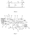
- Figure 3 is a schematic of an open circuit fault detection and location apparatus;
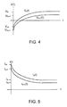
- Figure 4 is a graph of voltage versus time showing the resistive and capacitive voltage responses to a step function voltage applied to the circuit of Figure 2;
- Figure 5 is a graph of current versus time response to a step function voltage applied to the circuit of Figure 2; and
- Figure 6 is an equivalent circuit for a low frequency fault monitoring circuit with a resistive fault.
-
- Referring to the accompanying drawings, Figure 1 shows an equivalent circuit for a typical monitoring circuit, represented as a lossy transmission line. This includes a
monitoring conductor 10 extending the length of the cable being monitored and aground return path 12. The conductor has a resistance represented by resistor R and an inductance represented by inductor L. It is coupled to ground by a conductance represented by resistor G and by a capacitance represented by capacitor C. - The values of the parameters, resistance, inductance, conductance and capacitance, are expressed per unit length. For example the shunt capacitor's value may be expressed as a unit capacitance, that is capacitance per unit length such as µF/km. Thus, the capacitance can be expressed as:
- CTOTAL
- is the total capacitance to ground of the monitoring conductor;
- CLINE
- is the unit capacitance
- Length
- is the length of the cable
- At low frequencies the impedance Xi (=jωL) of the inductor L is much smaller than the resistance R, and the conductance G has an impedance much greater than impedance Xc (=jωC) of the capacitor. Therefore at low frequencies the lossy transmission line can be approximated as shown in Figure 2, with the inductor and conductance omitted.
- For applications such as a telephone long distance fibre optic cable, the metal shield or armour of the cable is used as the monitoring conductor. The primary transmission parameters for the cable shields are known. Using these known parameters, for example resistance per unit length and capacitance per unit length, it is possible to solve the problem at hand, finding the location of an open circuit fault on a cable as described in the following.
-
Equation 1 may be written as follows: - Since CLINE is a known value it follows that the length (or distance to the open circuit fault) is easily found once we obtain the total line capacitance CTOTAL . The measurement of the total line capacitance will now be discussed.
- Figure 3 is a schematic of an apparatus for detecting and locating open circuit faults. The
apparatus 14 includes avoltage source 16 connected to ground 18 and to acurrent meter 20 which is in turn connected to theshield 22 of acable 24. Avoltmeter 26 is connected between ground and thecable shield 22. Amicroprocessor 28 is connected to thevoltage source 16 to control its operation and to thecurrent meter 20 and thevoltage meter 26 through analogue todigital converters microprocessor 28 then stores the measurements inmemory 34. With this data available, the microprocessor is able to calculate the cable capacitance and the distance to the open fault. -
Formula 2 above shows that by measuring the total capacitance of cable under test, the location of the open fault can be determined. The apparatus illustrated in Figure 3 can measure the cable's total capacitance as described in the following. - The relationship amongst the charge on a capacitor, the voltage of the capacitor, and the capacitance is described by equation 3 below. The relationship between capacitive charge and current as a function of time is given in equation 4. These combine to give equation 5 which gives the charge as a function of current and time. The charge Q is calculated by integrating the current with respect to time over a defined period.
Where:
- C
- is Capacitance in Farads (F);
- Q
- is the charge on the capacitor in Coulombs (C);
- V
- is the potential across the capacitor in volts (V);
- i(t)
- is current flowing through the capacitor with respect to time in amperes (A);
- K
- is an initial value constant.
- To measure the charge Q of the cable capacitance, a voltage step is applied to the armour of the cable under test. At the same instant the microprocessor begins monitoring the current flowing into the armour at a given sampling frequency (FS ) over a time period T. The period T is long enough that the current approaches its infinite limit. Figures 5 and 6 show the typical response of a long fibre optic cable with 47µF capacitance and 1650Ω sheath resistance.
- Figure 4 shows the voltage Vr(t) across the series resistance R of the
conductor 10 illustrated in Figure 2. For the specific parameters given, the graph shows that the voltage drop across the equivalent resistor R approaches 0 after about 300ms. This agrees with the current shown in Figure 5, as the series current drops to a negligible value, so does the voltage drop across the resistor. Secondly, the graph in Figure 4 shows the voltage Vc(t) across the equivalent capacitance C of theconductor 10. Again, the voltage across the capacitor approaches the applied voltage after about 300ms. Since the capacitor looks like an open circuit at this time and the voltage drop due to the series resistance goes to 0, the voltage measured by the apparatus in Figure 3 accurately describes the voltage across the transmission line's capacitance (V from equation 3). - The current measurement samples must be read at a high enough frequency (FS ) to get an accurate numerical integration of the current. Since the current measurement samples are read by a microprocessor through an analogue to digital converter, the sampling rate can be easily controlled for the desired rate. The integration is fairly easy to perform numerically. The numerical integration is simply the area under the curve i(t). Since the sampling frequency is a finite value in real life, the integration can be approximated using the trapezoid rule as shown by equation 6.Where:

- Fs
- is the sampling frequency;
- i(0)
- is the current at the beginning of the sampling period;
- T
- is the sampling period; and
- K
- is an initial value constant.
- Substituting this into
equation 2, the length of the cable to the open is then calculated using equation 7.Where:
- L
- is length of conductor from said one end to the open circuit fault;
- Vf
- is the steady state capacitor voltage; and
- CLINE
- is the capacitance per unit length of the conductor;
- Fibre optic and other cables can be placed in all kinds of harsh environments. Many times 60Hz, 50 Hz or other frequency AC voltages will be induced on the cable under test. This can present multiple problems, corrupting the calculation of the charge Q on the cable, which would render any results invalid. In such a case, unwanted AC signals must be eliminated. Low pass or high pass filters are not a viable option because they could remove much of the information needed to perform a meaningful integration.
- To remove this unwanted noise, the integration is performed over a very specific period T. The period is long enough that the current and voltage reach steady state. The apparatus in Figure 3 can easily measure the minimum period by applying a step voltage to an uncharged cable and measuring the voltage and current until they reach steady state. After the minimum period has been determined the integration period T is selected to be a direct multiple of the period of the unwanted signal and longer than the minimum frequency determined. This method is effective in eliminating unwanted signals because the integration of a sinusoidal or other periodic signal over an integral multiple of the signal period equals 0. The processor provides precise clocking of the sampling frequency, so that the voltage and current can be read over the selected period to reject the unwanted induced AC noise.
- Additional problems arise with a resistively faulted cable. The lossy transmission line equivalent circuit at low frequencies for a cable under test with a fault resistance is shown in Figure 6. A fault resistance Rf is shown between the monitored
conductor 10 andground 12, representing the resistive fault. - In calculating the total charge (Q) on the line the extra DC current component due to the resistive fault causes the area under the curve i(t) (Figure 5) to be greater than it should be, therefore the capacitance measurement becomes erroneous. A method has been devised to help eliminate the effect of this DC current offset.
- Before the capacitance measurement algorithm is performed, a DC voltage is applied to the cable under test. Once the steady state voltage and current have been reached, the voltage and current are recorded, and the total DC resistance (Rdc) is calculated according to equation 8. This total DC resistance equals the fault resistance Rf plus the cable's sheath resistance R (equation 9). To ensure accuracy, positive and negative DC voltages are applied to the cable under test and the total DC resistance is calculated in both polarities. This compensates
- Since the voltage applied to the cable can be measured, the current error due to the fault resistance can be calculated and subtracted it from the calculation of the total charge Q to eliminate the DC errors. A formula for the charge on the cable (Q) incorporating these changes, can be derived as follows.
- iRf(t)
- is the resistive fault current; and
- ν(t)
- is the applied voltage.
- Using equation 6 and subtracting the resistive fault current:Where:

- T
- is the integration period; and
- K
- is the initial value constant.
- Now using the trapezoid rule, the charge on a cable with a resistive fault is:Where:

- FS
- is the current sampling frequency; and
- ν(0)
- is the voltage at the beginning of the sampling period.
- Substituting this total charge from
equation 12 into equation 3 we can obtain the total line capacitance. Since the capacitance per unit length is known and linear,equation 2 can be used to calculate the total distance to an open fault even on a cable with a resistively faulted conductor as follows.where:
- L
- is length of conductor to the open circuit fault;
- Fs
- is the sampling frequency;
- Vf
- is the steady state capacitor voltage;
- CLENGTH
- is the capacitance per unit length of the conductor;
- i(0)
- is the current at the beginning of the sampling period;
- i
- is the monitored current;
- T
- is the sampling period;
- iRf
- is the resistive DC current; and
- K
- is an initial value constant.
- The apparatus described and illustrated in Figure 3 can therefore be used to measure the total cable capacitance, and hence the distance to a cable "open" on a resistively faulted or non-faulted cable. With the microprocessor controller at the heart of the apparatus, a user interface can easily be added to make this into a portable instrument. Also, the apparatus may be incorporated into existing cable monitoring equipment to enhance its performance and effectiveness. The apparatus can be used to determine when a monitored section of cable becomes removed or "open" and determine the location of the open.
- While one embodiment of the present invention has been described in the foregoing, it is to be understood that other embodiments are possible within the scope of the invention. The invention is to be considered limited solely by the scope of the appended claims.
Claims (16)
- A method of locating an open circuit fault in an electric conductor extending along a cable and having a unit capacitance per unit length, said method including the steps of:and characterized in that:applying a step function voltage to one end of the conductor;measuring current in the conductor as a function of time;measuring voltage on the conductor; andcalculating from current and voltage measurements the location of the open circuit fault in the conductor,the current flowing into the conductor after application of the step function voltage is measured only at the one end of the conductor and over a sampling period until substantially steady state;the voltage on the conductor is measured only at the one end of the conductor; andthe distance between the one end of the conductor to the open circuit fault is computed from the current integrated over the sampling period, the steady state voltage on the conductor and the unit capacitance of the conductor.
- A method according to Claim 1 comprising measuring the current in the conductor by sampling the current at a predetermined sampling frequency.
- A method according to Claim 2 wherein the sampling frequency is an integral multiple of an AC mains power frequency.
- A method according to Claim 2 wherein the sampling frequency is selected from the group consisting of 50 Hz, 60 Hz and harmonics thereof.
- A method according to Claim 2 comprising calculating the distance between said one end of the conductor and the open circuit fault using:where:

- L
- is length of conductor from said one end to the open circuit fault;
- Fs
- is the sampling frequency;
- Vf
- is the steady state conductor voltage;
- CLINE
- is the capacitance per unit length of the conductor;
- i(0)
- is the current at the beginning of the sampling period;
- T
- is the sampling period; and
- K
- is an initial value constant.
- A method according to any one of Claims 1 to 5 wherein the conductor is a conductive shield of the cable.
- A method according to any one of Claims 1 to 6 further comprising the steps of:determining the resistance of the conductor;monitoring the voltage at said one end of the conductor over the sampling period;integrating the difference between the current measured over the sampling period and a resistive current calculated from the conductor resistance and the monitored voltage; andcomputing the distance between said one end of the conductor to the open circuit fault from the integrated difference and the unit capacitance of the conductor.
- A method according to Claim 7 comprising determining the conductor resistance by:applying a DC voltage to one end of the conductor;monitoring the DC voltage and DC current;allowing the DC voltage and DC current to reach steady state; andcalculating the conductor resistance from steady state values of the DC voltage and DC current.
- A method according to Claim 7 comprising determining the conductor resistance by:applying a positive DC voltage to one end of the conductor;monitoring the positive DC voltage and DC current;allowing the positive DC voltage and DC current to reach steady state;determining steady state values of the positive DC voltage and DC current;applying a negative DC voltage to one end of the conductor;monitoring the negative DC voltage and DC current;allowing the negative DC voltage and DC current to reach steady state; determining steady state values of the negative DC voltage and DC current; andcalculating the conductor resistance from the steady state values of the positive and negative DC voltages and currents.
- A method according to Claim 7, 8, or 9 comprising monitoring the DC current along the conductor by sampling the current at a predetermined sampling frequency.
- A method according to Claim 10 wherein the sampling frequency is an integral multiple of an AC mains power frequency.
- A method according to any one of Claims 7 to 11 wherein the sampling frequency is selected from the group comprising 50 Hz, 60 Hz and harmonics thereof.
- A method according to any one of Claims 7 to 11 comprising calculating the distance between said one end of the conductor and the open circuit fault using:where:

- L
- is length of conductor from said one end to the open circuit fault;
- Fs
- is the sampling frequency;
- Vf
- is the steady state capacitor voltage;
- CLENGTH
- is the capacitance per unit length of the conductor;
- i(0)
- is the current at the beginning of the sampling period;
- i
- is the monitored current;
- T
- is the sampling period;
- iRf
- is the resistive DC current; and
- K
- is an initial value constant.
- An apparatus for locating an open circuit fault in an electric conductor extending along a cable and having a unit capacitance per unit length, said apparatus comprising:a power supply for applying a step function voltage to one end of the conductor;a current meter connected to the one end of the conductor for measuring the current into the conductor over a sampling period;a voltage meter connected to the one end of the conductor for measuring the voltage on the conductor; anda processor for integrating the current measured over the sampling period and computing the distance between said one end of the conductor to the open circuit fault from the integrated current, the voltage on the conductor at the end of the sampling period and the unit capacitance of the conductor.
- An apparatus according to Claim 14 wherein the processor comprises means for sampling the current at a predetermined sampling frequency.
- An apparatus according to Claim 14 or 15 including a voltage meter for measuring the DC voltage at said one end of the conductor; and wherein the processor includes means for determining a conductor resistance, means for integrating the difference between the measured DC current over the sampling period and a resistive DC current calculated from the conductor resistance and the monitored DC voltage.
Applications Claiming Priority (2)
| Application Number | Priority Date | Filing Date | Title |
|---|---|---|---|
| CA2312509 | 2000-06-27 | ||
| CA002312509A CA2312509C (en) | 2000-06-27 | 2000-06-27 | Open cable locating for sheathed cables |
Publications (2)
| Publication Number | Publication Date |
|---|---|
| EP1167986A2 true EP1167986A2 (en) | 2002-01-02 |
| EP1167986A3 EP1167986A3 (en) | 2003-08-20 |
Family
ID=4166581
Family Applications (1)
| Application Number | Title | Priority Date | Filing Date |
|---|---|---|---|
| EP00309126A Withdrawn EP1167986A3 (en) | 2000-06-27 | 2000-10-17 | Open cable locating for sheathed cables |
Country Status (3)
| Country | Link |
|---|---|
| US (1) | US6459271B1 (en) |
| EP (1) | EP1167986A3 (en) |
| CA (1) | CA2312509C (en) |
Cited By (5)
| Publication number | Priority date | Publication date | Assignee | Title |
|---|---|---|---|---|
| US6590962B1 (en) * | 2000-06-21 | 2003-07-08 | Teradyne, Inc. | Method of performing non-interactive resistive fault location |
| WO2008132639A2 (en) * | 2007-04-26 | 2008-11-06 | Schlumberger Canada Limited | Determining electrical characteristics of an electrical cable |
| CN103399038A (en) * | 2012-02-29 | 2013-11-20 | 苹果公司 | Device and method for testing flexible cable shielding layer |
| CN112464518A (en) * | 2020-09-02 | 2021-03-09 | 国网天津市电力公司电力科学研究院 | Equivalent circuit and method for calculating steady-state current when people contact with vehicle |
| US20220206054A1 (en) * | 2019-04-30 | 2022-06-30 | Koninklijke Philips N.V. | Locating an error in a supply or signal line of a magnetic resonance system |
Families Citing this family (9)
| Publication number | Priority date | Publication date | Assignee | Title |
|---|---|---|---|---|
| US20030035376A1 (en) * | 2001-08-20 | 2003-02-20 | Xiaofen Chen | Derivation of composite step-function response |
| US6657436B1 (en) * | 2001-10-30 | 2003-12-02 | At&T Corp. | Sheath monitoring technique |
| US7756812B2 (en) * | 2005-09-22 | 2010-07-13 | Eastman Kodak Company | Adaptive input-cell circuitry useful in configurable electronic controllers |
| US7282927B1 (en) | 2006-06-21 | 2007-10-16 | Eastman Kodak Company | Use of a configurable electronic controller for capacitance measurements and cable break detection |
| US7420152B2 (en) | 2006-09-07 | 2008-09-02 | Eastman Kodak Company | Wide-range linear output photo sensor circuit |
| EP2120058A2 (en) * | 2008-05-14 | 2009-11-18 | Acterna, LLC | Locating a low-resistance fault in an electrical cable |
| US8058879B1 (en) | 2009-01-06 | 2011-11-15 | Atherton John C | Voltage indicating coupling for metal conduit systems |
| EP2936173A1 (en) * | 2012-12-18 | 2015-10-28 | Koninklijke Philips N.V. | Problem detection in cable system |
| JP2015002554A (en) * | 2013-06-18 | 2015-01-05 | 船井電機株式会社 | Wired communication device and wired communication method |
Citations (6)
| Publication number | Priority date | Publication date | Assignee | Title |
|---|---|---|---|---|
| US3434049A (en) * | 1965-12-06 | 1969-03-18 | Tektronix Inc | Time domain reflectometry system having a current source for locating discontinuities in a transmission line |
| US3617880A (en) * | 1970-05-15 | 1971-11-02 | Northern Electric Co | Time domain reflectometer |
| US4109117A (en) * | 1977-09-02 | 1978-08-22 | The United States Of America As Represented By The Secretary Of The Navy | Range division multiplexing |
| GB2065312A (en) * | 1979-11-16 | 1981-06-24 | Post Office | Location of Cross-talk Faults by Correlation |
| US4475079A (en) * | 1978-05-31 | 1984-10-02 | Bicc Public Limited Company | Apparatus for locating faults in electric cables |
| US6016464A (en) * | 1996-07-10 | 2000-01-18 | Lecroy Corporation | Method and system for characterizing terminations in a local area network |
Family Cites Families (3)
| Publication number | Priority date | Publication date | Assignee | Title |
|---|---|---|---|---|
| US4320338A (en) * | 1980-01-08 | 1982-03-16 | Northern Telecom, Inc. | Methods of and apparatus for determining the capacitance of a transmission line by integrating line currents |
| FI81682C (en) * | 1986-12-29 | 1990-11-12 | Elecid Ab Oy | Cable break detector |
| US6181140B1 (en) * | 1998-06-08 | 2001-01-30 | Norscan Inc. | Method of estimating the location of a cable break including a means to measure resistive fault levels for cable sections |
-
2000
- 2000-06-27 CA CA002312509A patent/CA2312509C/en not_active Expired - Fee Related
- 2000-10-17 EP EP00309126A patent/EP1167986A3/en not_active Withdrawn
- 2000-11-13 US US09/709,420 patent/US6459271B1/en not_active Expired - Lifetime
Patent Citations (6)
| Publication number | Priority date | Publication date | Assignee | Title |
|---|---|---|---|---|
| US3434049A (en) * | 1965-12-06 | 1969-03-18 | Tektronix Inc | Time domain reflectometry system having a current source for locating discontinuities in a transmission line |
| US3617880A (en) * | 1970-05-15 | 1971-11-02 | Northern Electric Co | Time domain reflectometer |
| US4109117A (en) * | 1977-09-02 | 1978-08-22 | The United States Of America As Represented By The Secretary Of The Navy | Range division multiplexing |
| US4475079A (en) * | 1978-05-31 | 1984-10-02 | Bicc Public Limited Company | Apparatus for locating faults in electric cables |
| GB2065312A (en) * | 1979-11-16 | 1981-06-24 | Post Office | Location of Cross-talk Faults by Correlation |
| US6016464A (en) * | 1996-07-10 | 2000-01-18 | Lecroy Corporation | Method and system for characterizing terminations in a local area network |
Cited By (8)
| Publication number | Priority date | Publication date | Assignee | Title |
|---|---|---|---|---|
| US6590962B1 (en) * | 2000-06-21 | 2003-07-08 | Teradyne, Inc. | Method of performing non-interactive resistive fault location |
| WO2008132639A2 (en) * | 2007-04-26 | 2008-11-06 | Schlumberger Canada Limited | Determining electrical characteristics of an electrical cable |
| WO2008132639A3 (en) * | 2007-04-26 | 2009-09-24 | Schlumberger Canada Limited | Determining electrical characteristics of an electrical cable |
| CN103399038A (en) * | 2012-02-29 | 2013-11-20 | 苹果公司 | Device and method for testing flexible cable shielding layer |
| CN103399038B (en) * | 2012-02-29 | 2017-02-22 | 苹果公司 | Device and method for testing flexible cable shielding layer |
| US20220206054A1 (en) * | 2019-04-30 | 2022-06-30 | Koninklijke Philips N.V. | Locating an error in a supply or signal line of a magnetic resonance system |
| CN112464518A (en) * | 2020-09-02 | 2021-03-09 | 国网天津市电力公司电力科学研究院 | Equivalent circuit and method for calculating steady-state current when people contact with vehicle |
| CN112464518B (en) * | 2020-09-02 | 2022-06-17 | 国网天津市电力公司电力科学研究院 | Equivalent circuit and method for calculating steady-state current when people contact with vehicle |
Also Published As
| Publication number | Publication date |
|---|---|
| CA2312509A1 (en) | 2001-12-27 |
| CA2312509C (en) | 2003-11-18 |
| EP1167986A3 (en) | 2003-08-20 |
| US6459271B1 (en) | 2002-10-01 |
Similar Documents
| Publication | Publication Date | Title |
|---|---|---|
| US6459271B1 (en) | Open cable locating for sheathed cables | |
| US4766549A (en) | Single-ended transmission line fault locator | |
| EP1042651B1 (en) | Electrode integrity checking | |
| EP1736788B1 (en) | Apparatus for searching electromagnetic disturbing source | |
| US6470283B1 (en) | Non-contact self-powered electric power monitor | |
| Bascom et al. | Computerized underground cable fault location expertise | |
| JP4267713B2 (en) | Degradation diagnosis method for power cables | |
| CN102971636A (en) | Apparatus and method for measuring the dissipation factor of an insulator | |
| US20050021254A1 (en) | Method and apparatus for determining the complex impedance of an electrical component | |
| EP3779474B1 (en) | Measuring electrical energy consumption | |
| US4022990A (en) | Technique and apparatus for measuring the value of a capacitance in an electrical circuit such as a telephone communication line | |
| Javaid et al. | High pass filter based traveling wave method for fault location in VSC-Interfaced HVDC system | |
| KR100219981B1 (en) | Measurment method and apparatus for earth impedance in high frequency region | |
| RU2739386C2 (en) | Method for determination of insulation resistance reduction point | |
| JP2004045118A (en) | Fault point survey method for overhead distribution line | |
| JP3663286B2 (en) | Cable insulation deterioration diagnosis method | |
| JP3010367B2 (en) | Insulation resistance measurement method of cable sheath under hot wire | |
| JPH07294588A (en) | Method for locating insulation failure section of live cable | |
| JP3246309B2 (en) | Deterioration detection device for zinc oxide arrester | |
| CN102959409A (en) | Apparatus and method for measuring dissipation factor of insulator | |
| CN115144791B (en) | Method and system for online detection of high-voltage cable armor grounding state | |
| JP3034651B2 (en) | Diagnosis method for insulation of CV cable | |
| JPH0627766B2 (en) | CV cable insulation deterioration diagnosis device | |
| JPS596137Y2 (en) | Insulation monitoring device for rotating machine windings | |
| RU2028634C1 (en) | Method of and device for insulation resistance measurement in alternating-current lines incorporating static converters |
Legal Events
| Date | Code | Title | Description |
|---|---|---|---|
| PUAI | Public reference made under article 153(3) epc to a published international application that has entered the european phase |
Free format text: ORIGINAL CODE: 0009012 |
|
| AK | Designated contracting states |
Kind code of ref document: A2 Designated state(s): AT BE CH CY DE DK ES FI FR GB GR IE IT LI LU MC NL PT SE |
|
| AX | Request for extension of the european patent |
Free format text: AL;LT;LV;MK;RO;SI |
|
| PUAL | Search report despatched |
Free format text: ORIGINAL CODE: 0009013 |
|
| AK | Designated contracting states |
Designated state(s): AT BE CH CY DE DK ES FI FR GB GR IE IT LI LU MC NL PT SE |
|
| AX | Request for extension of the european patent |
Extension state: AL LT LV MK RO SI |
|
| RIC1 | Information provided on ipc code assigned before grant |
Ipc: 7G 01R 31/11 B Ipc: 7G 01R 31/08 A |
|
| AKX | Designation fees paid | ||
| REG | Reference to a national code |
Ref country code: DE Ref legal event code: 8566 |
|
| STAA | Information on the status of an ep patent application or granted ep patent |
Free format text: STATUS: THE APPLICATION IS DEEMED TO BE WITHDRAWN |
|
| 18D | Application deemed to be withdrawn |
Effective date: 20040221 |